Introduction
This tutorial is a continuation of the Tutorial 2. In here, we are going to create a 4-bit counter using 4 on-board LEDs(LD0, LD1, LD2 and LD3). This is also controlling GPIO using AXI interface by using AXI GPIO IP.
This tutorial will include,
1.Make the hardware design and export the hardware design file using Vivado
2.Create the application project using MATLAB Simulink and Waijung 2 for ZYNQ-7000
Make the hardware design using Vivado
1.Since this tutorial is a continue version of Tutorial 2, we can use the Vivado hardware design file(XSA) file from the previous tutorial or you can create a new Vivado project as same as Tutorial 2 (from step1 to step20)
Create the application project using MATLAB Simulink and Waijung 2 ZYNQ-7000 blockset
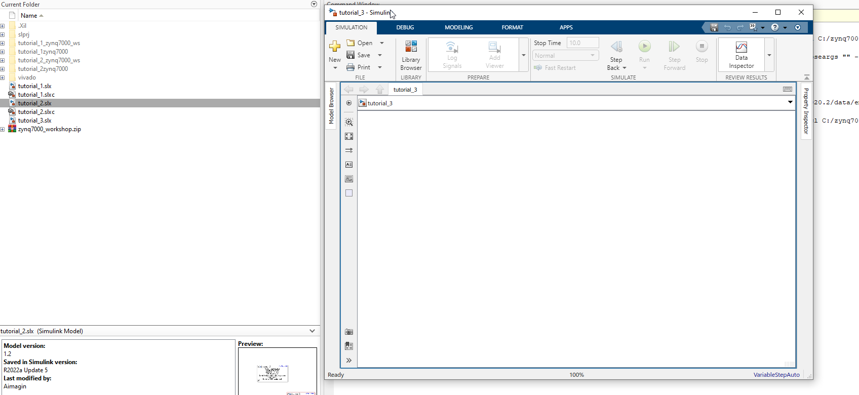
1.Open MATLAB and change the current folder of MATLAB to a path where it doesn't contain any spaces
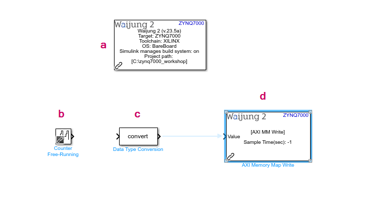
2.Add following blocks to the current Simulink model. To add the blocks, click on a empty white space on the Simulink model and type the block name
a.Waijung 2 Target Setup
b.Counter Free-Running
c.Data Type Conversion
d.AXI Memory Map Write
3.Then, configure the added blocks as follows
a.Waijung 2 Target Setup
i.Set the Xilinx Tool Path in Waijung 2 tab. This is the path to the folder that you have installed Vivado and Vitis
ii.Browse the XSA (hardware design file) in ZYNQ7000 tab that we exported from the Vivado and wait until the process is finished
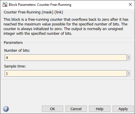
b.Counter Free-Running
i.Set the Number of bits to 4 since it is 4-bit counter
ii.Set the sample time to 1 Sec to count up per 1 second
c.AXI Memory Map Write
i.Set the base address as 0x41200000, since the base address of the AXI GPIO IP. In here we are going to control 4 GPIOs using 4-bit counter value. The base address of the AXI GPIO IP contains the statuses of GPIOs (here it is only 4-bit. but it can go up to maximum 32 bit or 32 GPIOs). Following table represents how the value we are going to write to the base address and how the 4 GPIOs will react according to the value
Counter value |
LD3 |
LD2 |
LD1 |
LD0 |
0 |
0 |
0 |
0 |
0 |
1 |
0 |
0 |
0 |
1 |
2 |
0 |
0 |
1 |
0 |
3 |
0 |
0 |
1 |
1 |
4 |
0 |
1 |
0 |
0 |
5 |
0 |
1 |
0 |
1 |
6 |
0 |
1 |
1 |
0 |
7 |
0 |
1 |
1 |
1 |
8 |
1 |
0 |
0 |
0 |
9 |
1 |
0 |
0 |
1 |
10 |
1 |
0 |
1 |
0 |
11 |
1 |
0 |
1 |
1 |
12 |
1 |
1 |
0 |
0 |
13 |
1 |
1 |
0 |
1 |
14 |
1 |
1 |
1 |
0 |
15 |
1 |
1 |
1 |
1 |
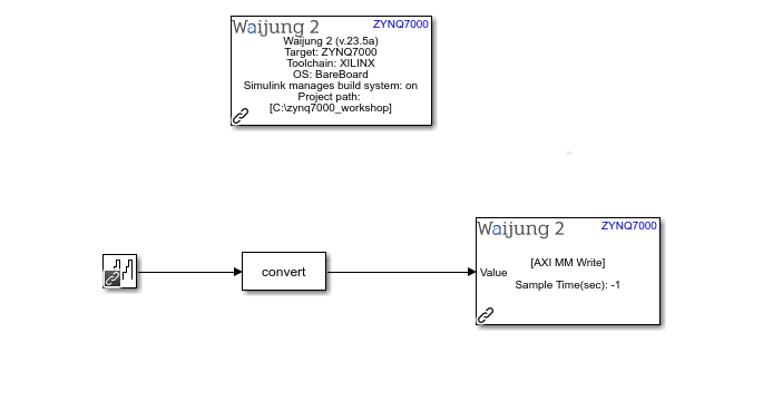
4.Connect the following blocks in the Simulink model
5.Go to the APPS tab in the Simulink model. Then select Embedded Coder. Then go to C CODE tab and Click the Build button to build the Simulink model and download it to the hardware. Wait until the process is finished
6.After it is successfully download it to the hardware, the LD0, LD1, LD2 and LD3 LEDs will ON and OFF according to the counter value .
Resources
Simulink model: tutorial_3.slx
XSA file: tutorial2_wrapper.xsa
Vivado project: basic_tutorial2.zip