Introduction
This tutorial will guide you to create a simple blinking LED application project using AXI interface. AXI interface is the main communication interface between the PS and PL. The AXI interface provides high bandwidth and low latency data transfer. This communication is based on Master-Slave communication. There are 3 types of AXI interfaces.
1.AXI4 (For high-performance memory-mapped)
2.AXI4-Lite (low-throughput memory-mapped communication)
3.AXI4 -Stream (For high-speed streaming data)
AXI GPIO supports only AXI4-Lite. This tutorial will elaborate how to setup and configure the AXI interface and communicate using the AXI4-Lite interface
This will include,
1.Make the hardware design and export the hardware design file using Vivado
2.Create the application project using MATLAB Simulink and Waijung 2 for ZYNQ-7000
Make the hardware design using Vivado
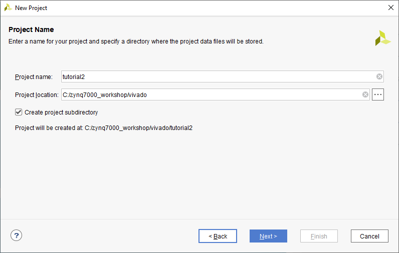
1.Create a new project and name it as tutorial2. You can refer the Tutorial 1 to create a new Vivado project(from step1 to step 12). Name the project as tutorial2 instead of tutorial1.
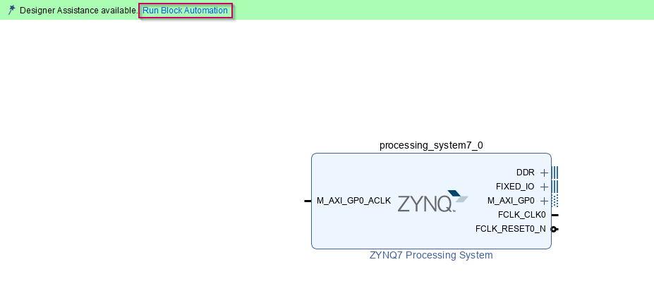
2.Import the ZYNQ7 Processing System IP and run block automation(in step 12 in Tutorial 1)
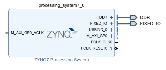
3.Once the block automation is done final IP is as below
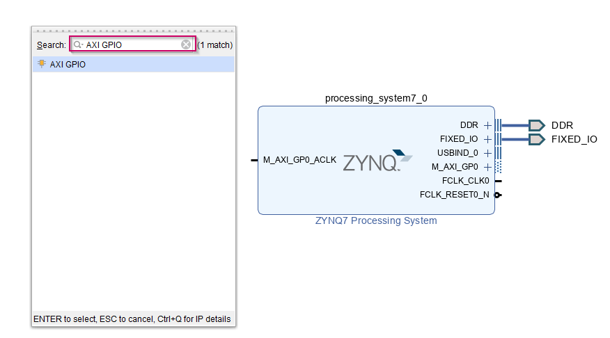
4. Then we need to add next IP, AXI GPIO IP to control the GPIO using AXI interface. To add the AXI GPIO IP, click on the empty white space in the design and press Ctrl + I.
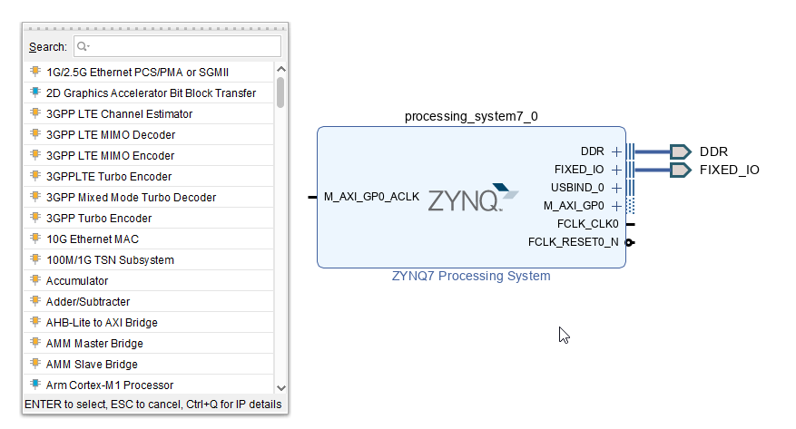
5.Search for AXI GPIO in the search list and add it to the current design
6.Once it is added, double click on the AXI GPIO IP to configure. Set the GPIO interface as led 4bits from the drop-down list to use onboard 4 LEDs (LD0(M14), LD1(M15), LD2(G14) and LD3(D18))
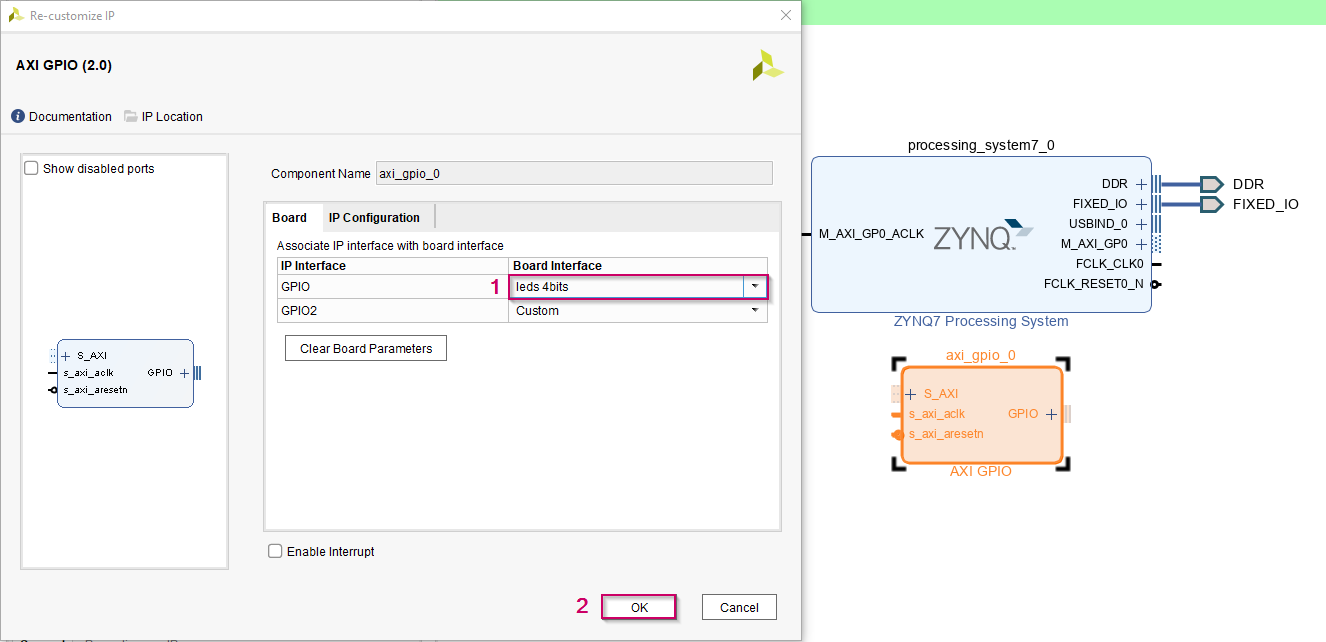
Note: In case if you need to use custom pins you can select custom option. Then you can select relevant FPGA pins in the Schematic in Synthesis as we did in Tutorial 1.
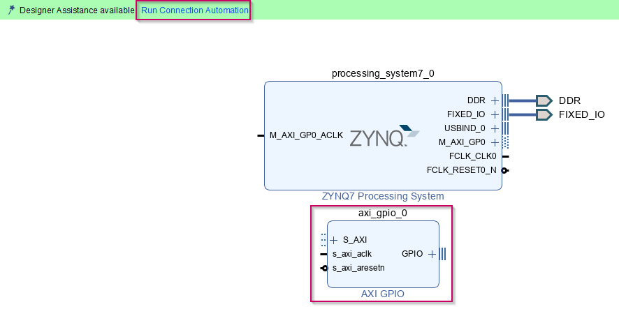
7.Then click on Run Connection Automation.
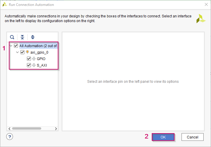
8.Then enable all options and click OK to automatically add required IPs and connect them to setup the AXI interface
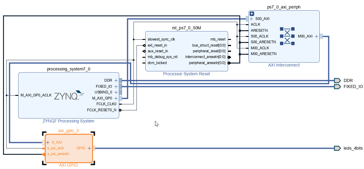
9. Once the connection automation is done, the final design will be as below. Newly automatically added AXI Interconnect IP will be used to control and manage the traffic through AXI interface between Masters and Slaves
10.We need the base address of the AXI GPIO IP when we are going to create the Simulink model to control the GPIOs. To get the base address go to the Address Editor tab and copy the Master Base Address and save it in a notepad or text editor for future use
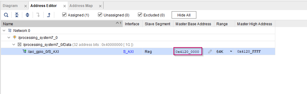
Note: When you are copying the memory address please remove '_' in between 4120 and 0000
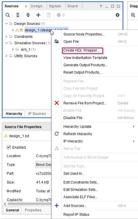
11.Save the project and create the HDL wrapper first by right clicking on design_1 and selecting Create HDL Wrapper. Click OK to the pop-up window and wait for the process to end(click OK to the warning messages)
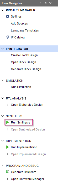
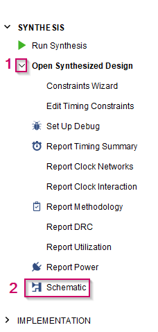
12. To set the FPGA pins, first click on Run Synthesis and wait for the process is completed. Then click Cancel to the pop-up message
13. Then go to Schematic under Synthesis
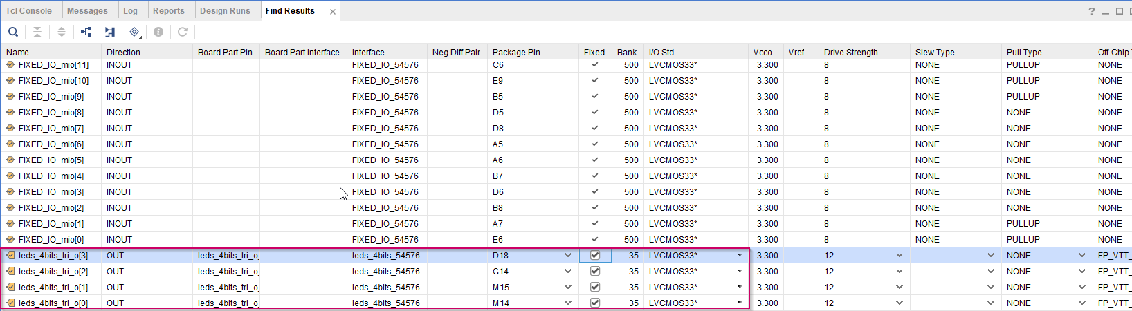
14. In the Schematic tab, click on I/O Ports to get the list of the assigned pin list of the current hardware configuration
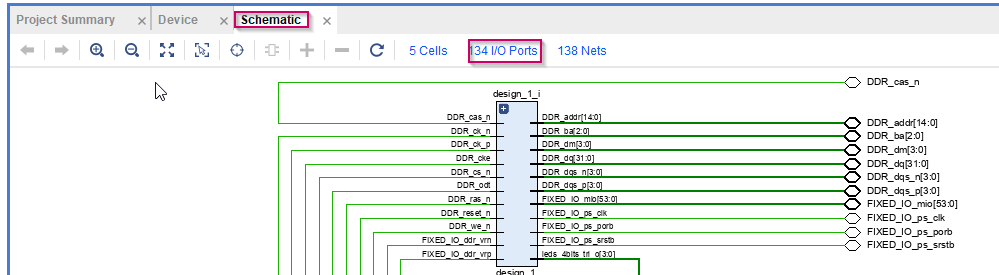
15. Make sure all the pins are automatically selected for led_4bits_tri0 signals
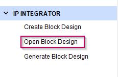
16. Then click on Open Block Design
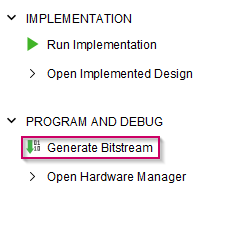
17.Next we need to generate the bit-stream for this hardware design. For that click on Generate Bitstream in the bottom of the left pane. Then click Yes to the pop-up window
18. Wait until the process is finished. Once it is finished, there will be a pop-up window. Click Cancel to that
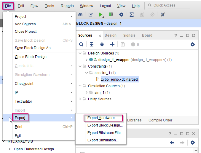
19. Last step is to export the hardware design file. For that, go to File → Export → Export Hardware.
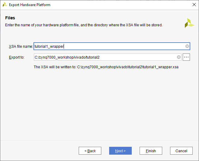
20. Click Next on the wizard. Next, select Include Bitstream from the selection and click Next. Then give a proper name for the hardware design file(XSA). Click Next and at last click Finish
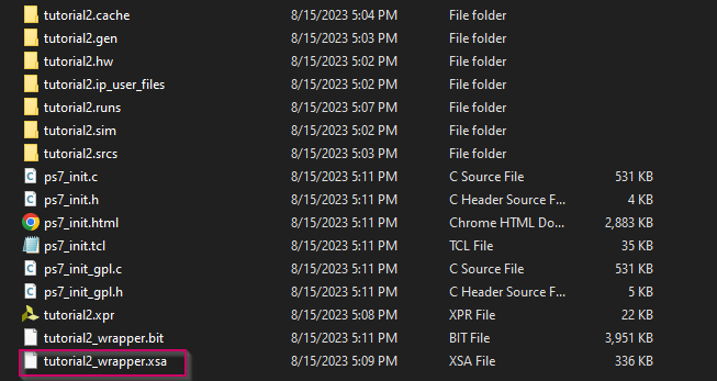
21. You can find the XSA file in the project folder. This will be needed for the Waijung 2 blockset
Create the application project using MATLAB Simulink and Waijung 2 ZYNQ-7000 blockset
1.Open MATLAB and change the current folder of MATLAB to a path where it doesn't contain any spaces
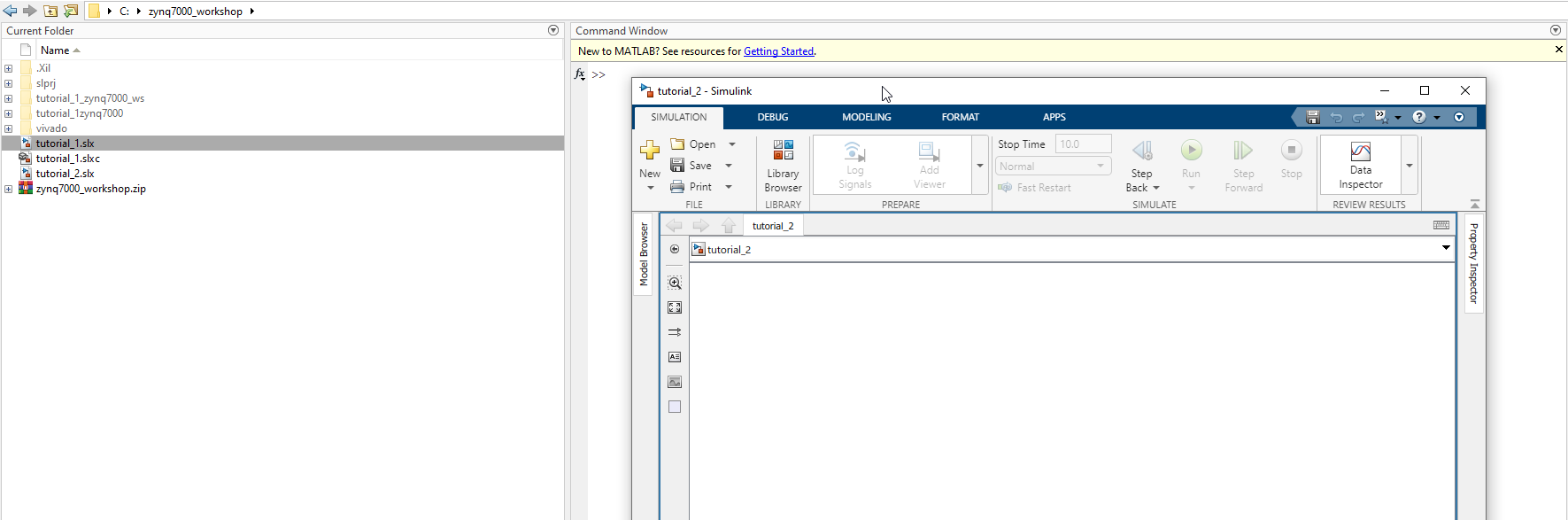
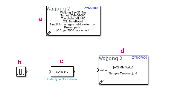
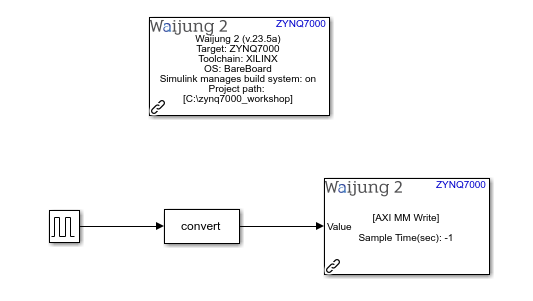
2.Add following blocks to the current Simulink model. To add the blocks, click on a empty white space on the Simulink model and type the block name
a.Waijung 2 Target Setup
b.Pulse Generator
c.Data Type Conversion
d.AXI Memory Map Write
3.Then, configure the added blocks as follows
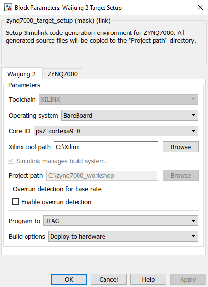
a.Waijung 2 Target Setup
i.Set the Xilinx Tool Path in Waijung 2 tab. This is the path to the folder that you have installed Vivado and Vitis
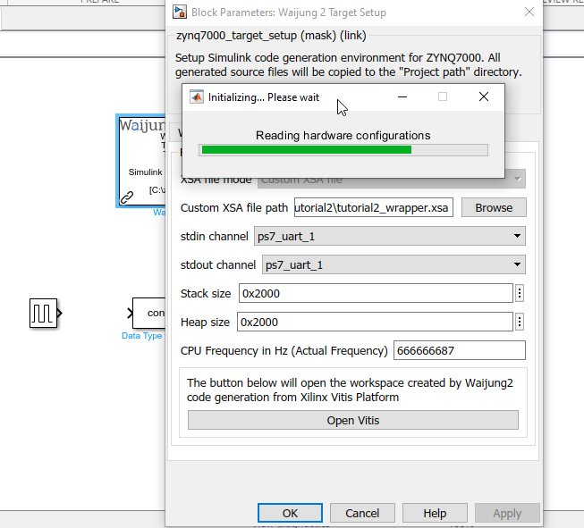
ii.Browse the XSA (hardware design file) in ZYNQ7000 tab that we exported from the Vivado and wait until the process is finished
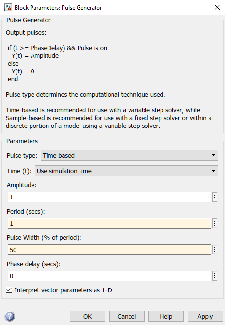
b.Pulse Generator
i.Set the Period to 1 and Pulse width to 50 to generate the 1Hz square wave
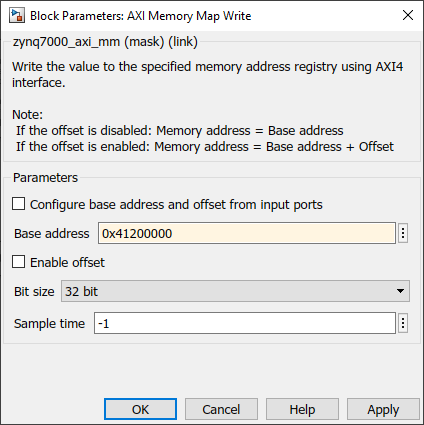
c.AXI Memory Map Write
i.AXI memory map write is used to write values to the given memory register. Here we are going to write the GPIO output status to the given base address of the AXI GPIO IP. The base address of the AXI GPIO IP stores the status of the GPIO. The base address for the IP is 0x41200000
4.Connect the following blocks in the Simulink model
5.Go to the APPS tab in the Simulink model. Then select Embedded Coder. Then go to C CODE tab and Click the Build button to build the Simulink model and download it to the hardware. Wait until the process is finished
6.After it is successfully download it to the hardware, the LD0 LED will start to blink at 1Hz.
Resources
Simulink model: tutorial_2.slx
XSA file: tutorial2_wrapper.xsa
Vivado project: basic_tutorial2.zip