Introduction
This tutorial will guide you to create a simple blinking LED application project using EMIO interface. Using EMIO interface, we can control I/O pins which are connected to the PL(FPGA) using GPIO driver.
This will include,
1.Make the hardware design and export the hardware design file using Vivado
2.Create the application project using MATLAB Simulink and Waijung 2 for ZYNQ-7000
Make the hardware design using Vivado
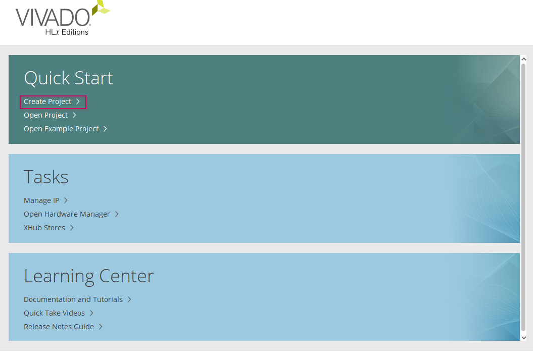
1.Open the Vivado design suite
2.Create new project
3.Click on Next
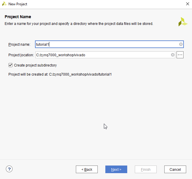
4.Provide a proper name and a location for the project. Click Next to continue.
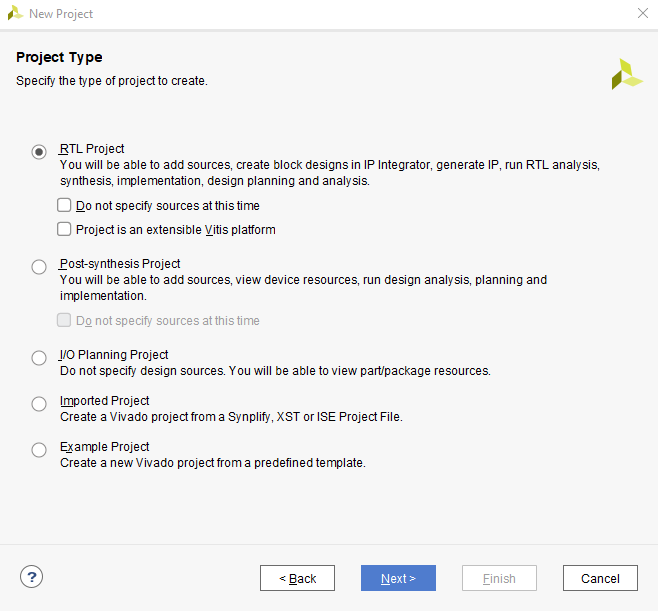
5.Select RTL Project and click Next.
6.Click Next for Add Sources and Add Constraints
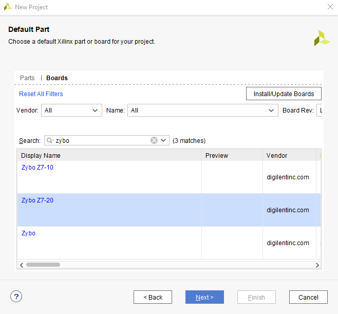
7.Then, select Zybo Z7-20 board under Boards and click Next
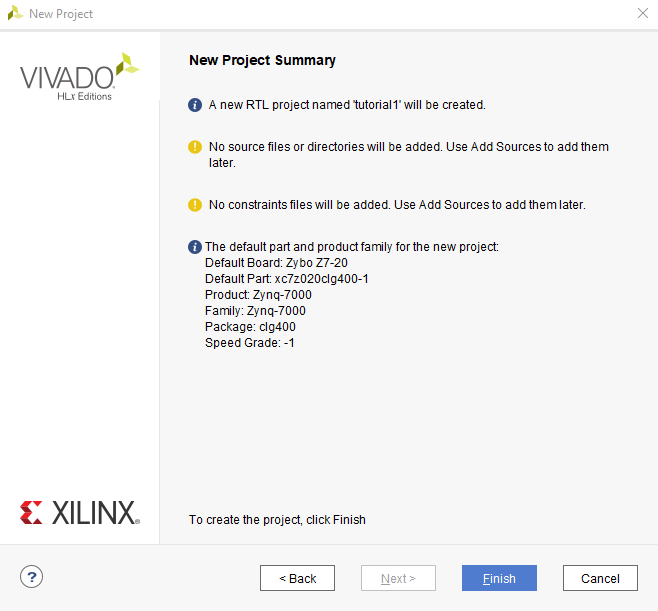
8.At last, click on Finish.
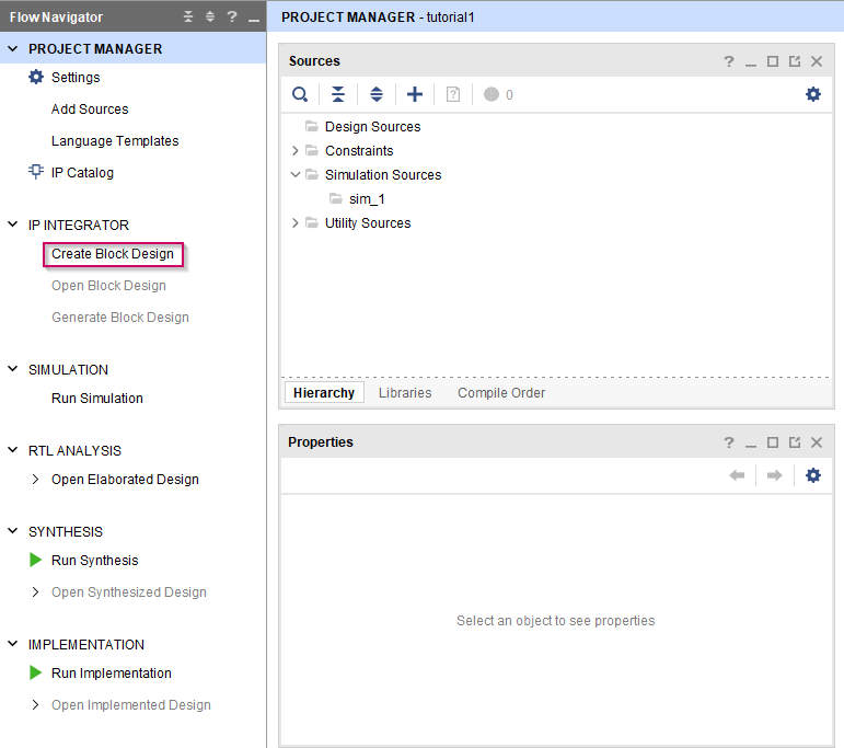
9.Once the project is loaded, go to Create Block Design
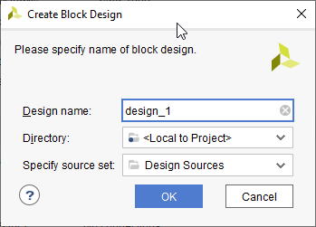
10. Click OK to create the block design with the given name
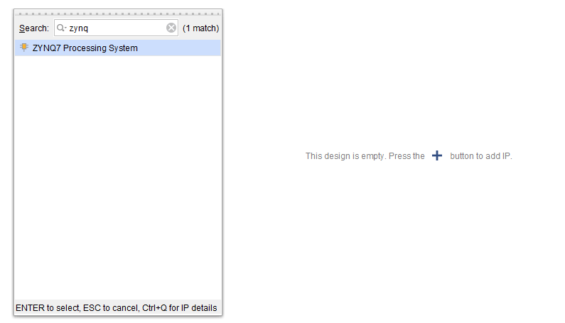
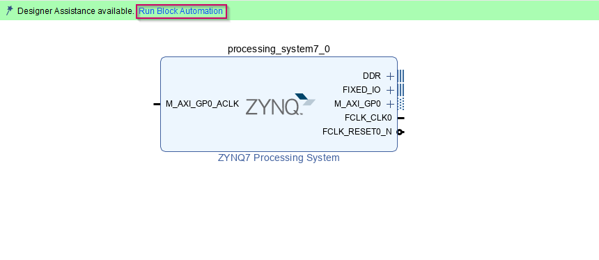
11. Once the blank diagram, click on  or use Ctrl + i to add Vivado IPs to the diagram. Only ZYNQ7 Processing System IP is required for this project. Add ZYNQ7 Processing System IP to the diagram.
12. Then click on Run Block Automation to configure the IP automatically according to the hardware and click OK.
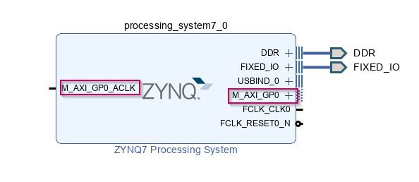
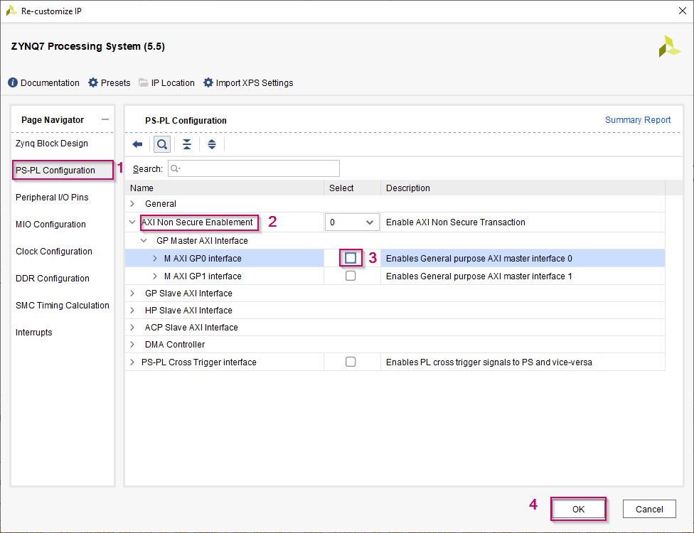
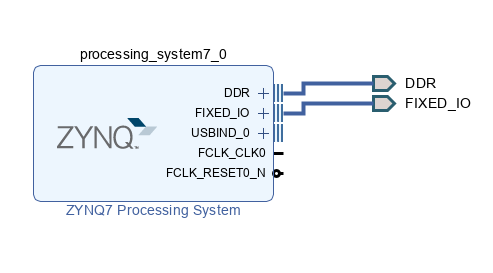
13. Unnecessary ports and interfaces can be removed from the IP. In here, M_AXI_GP0 is not required for this project. To remove it, double click on the ZYNQ7 Processing System IP. Then go to PS-PL Configuration, expand AXI Non Secure Enablement, expand GP Master AXI Interface and disable M AXI GP0. Next click OK
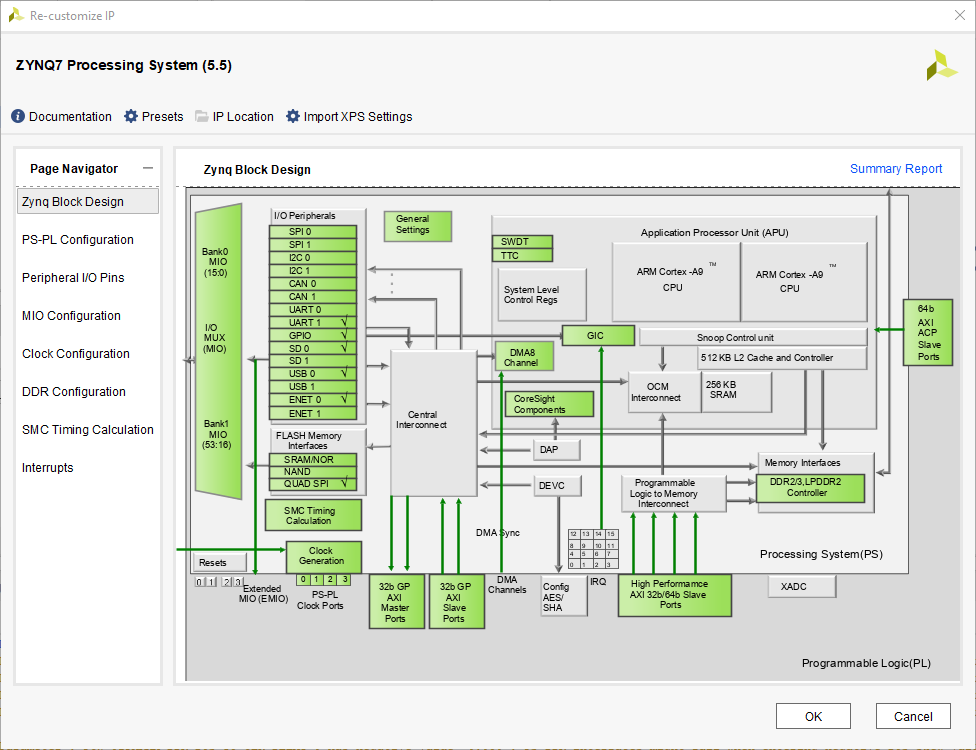
14. Since we are going to control pin in FPGA fabric, the pin should be connected to the ZYNQ7 Processing System IP externally. The Processing System(PS) doesn't have a direct connection to the FPGA I/O pins, those pins should be connected to the PS externally using EMIO interface. To do that, double click on the ZYNQ7 Processing System IP to open the IP configuration.
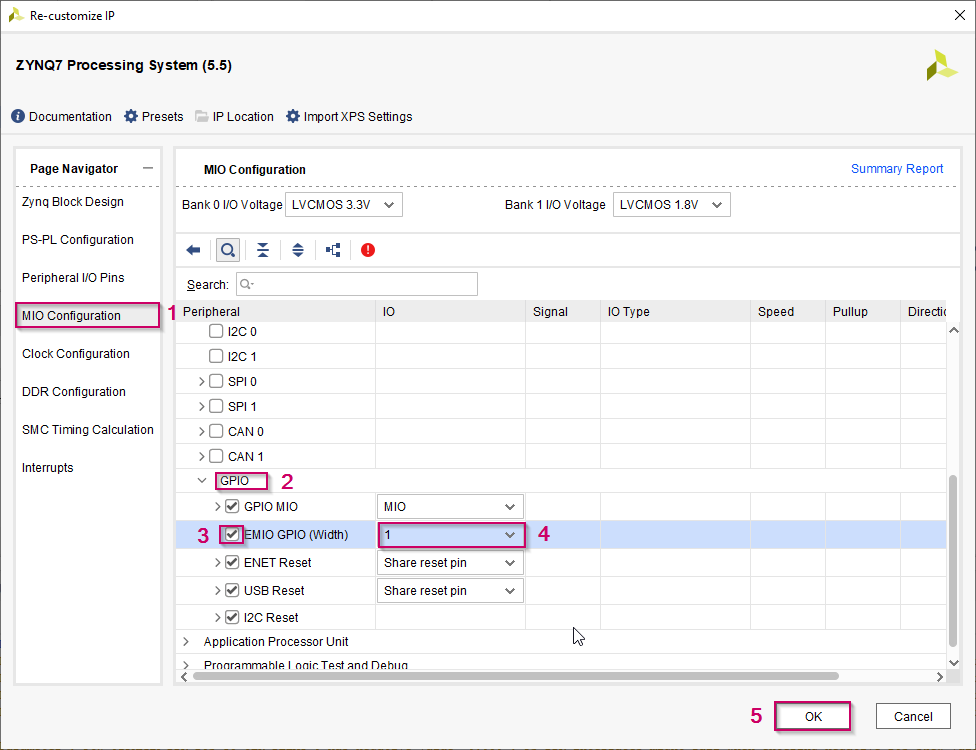
15. Then go to MIO Configuration and scroll down until you find GPIO section. Next, expand the GPIO section, Enable EMIO GPIO and set the width as 1 since we are going to only one pin. Then click OK.
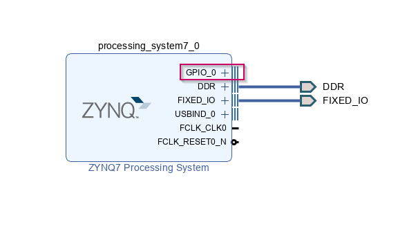
16. Click OK to the pop-up windows if you get any warning messages. Once it is done, you will see a new port GPIO_0 in the ZYNQ7 Processing System IP. That is the port that we are going to connect the FPGA pin.
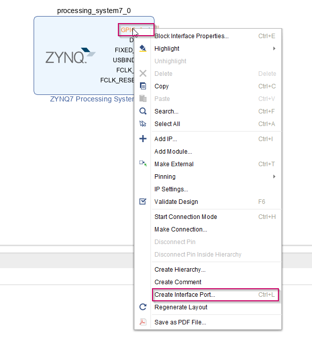
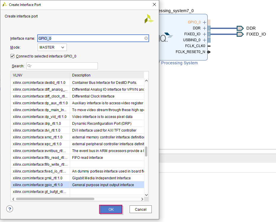
17. To connect the external pin, right click on GPIO_0 port and click on Create Interface Port
18. Then click OK the pop-up window
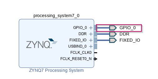
19. Once it is done, you will see an external port connected to the GPIO_0 port
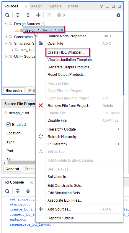
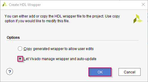
20. Then save the project. Next step is to set the correct LED pin to the external port that we created above. There are two ways to define the FPGA pins to the external port. First way is, manually write a constraint file to define pins, second way is to use the Vivado system to generate the constraint file automatically. In this tutorial the constraint file will be generated using the Vivado system. To do that first we have to create HDL wrapper. Go to Design Sources under Sources. Then right click on design_1 and select Create HDL Wrapper. Select Let Vivado manage wrapper and auto-update from the selection and click OK.
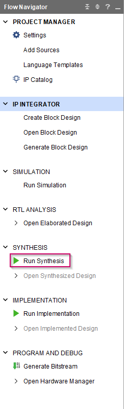
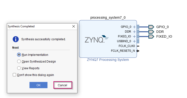
21. Once that process is finished, click on Run Synthesis to synthesis the hardware design and wait until the process is finished. Once the process is finished click Cancel on the pop-up window.
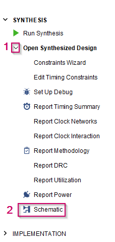
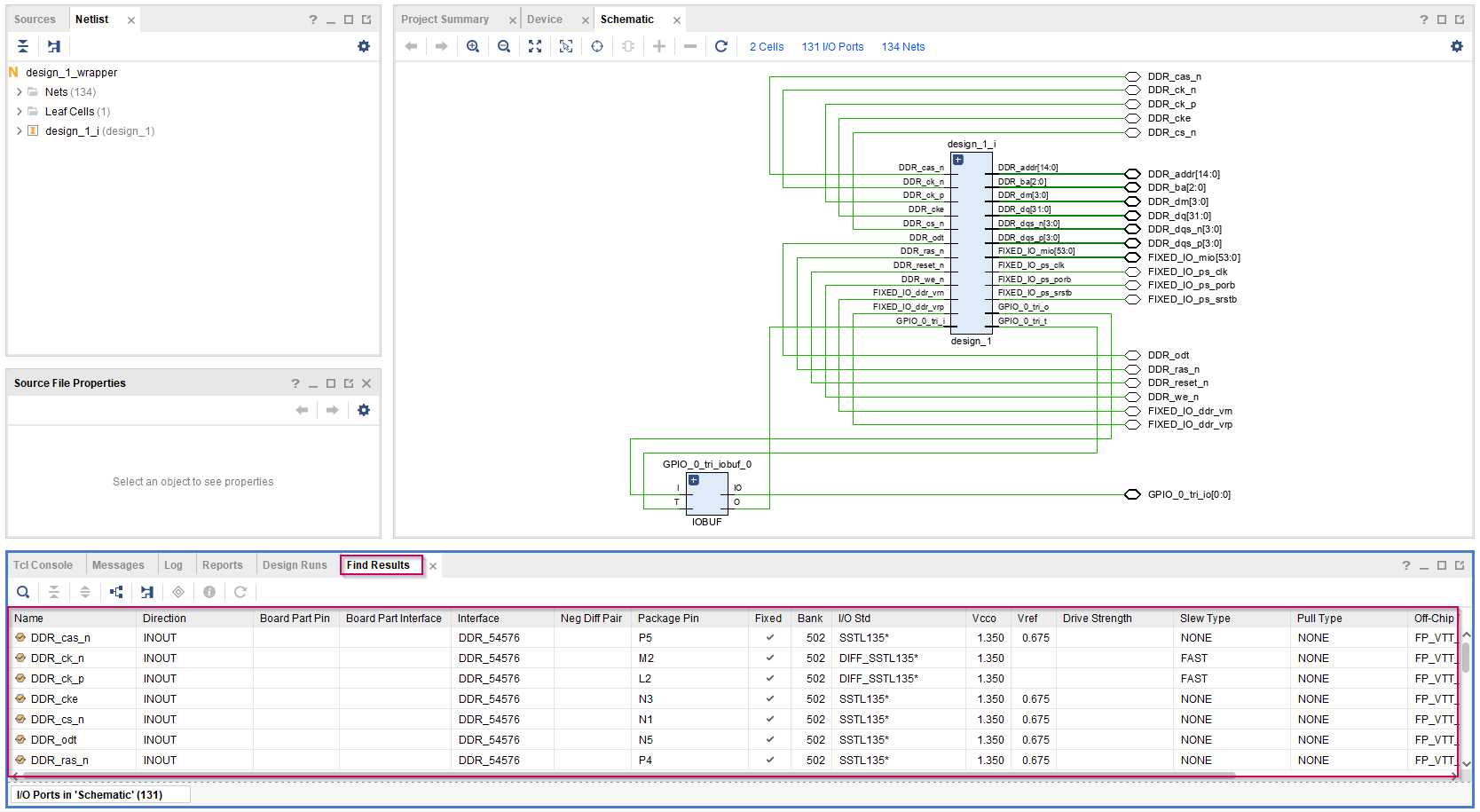
22. Then expand the Open Synthesized Design and click on Schematic to set the pins
23. In the Schematic tab, click on I/O Ports to get the list of the assigned pin list of the current hardware configuration
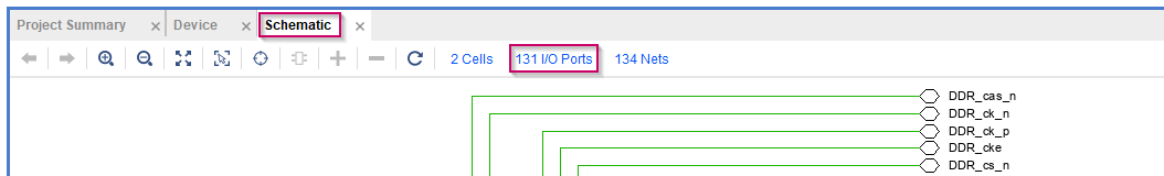
24.Once you click on I/O Ports separate Find Results tab will be appeared in the bottom pane. In there you can the list of pins and their configurations
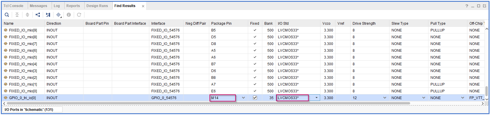
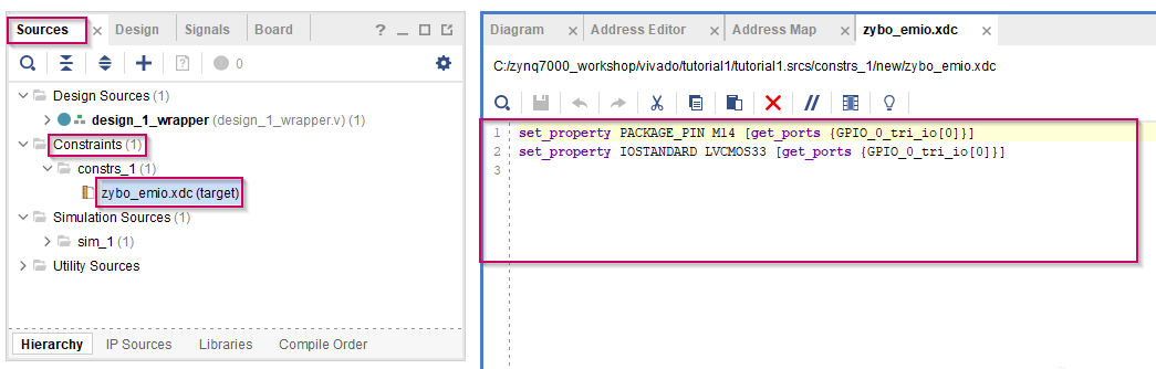
25. Scroll down until you find the GPIO_0_tri_io[0] signal name. Since we are going to use LD0 LED (M14 pin) to blink set the Package Pin M14 for the GPIO_0_tri_io[0] and set the I/O Std as LVCMOS33 to use 3.3V.
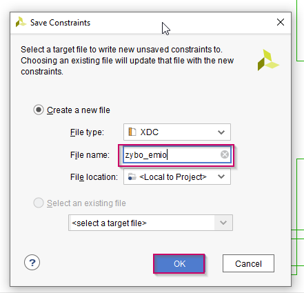
26. Once it is done, save the project. Then click OK to the pop-up window. After that there will be another pop-up window to save above configurations to a constraint file(.xdc). Give a proper file name to that and click OK to save it
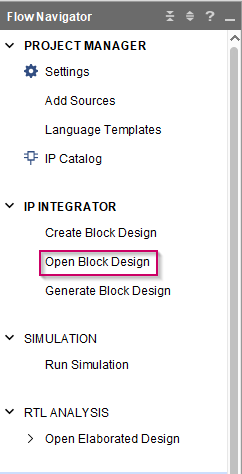
27. Then click on Open Block Design. If you need to see the generated constraint file for this design, you can go to Source tab in the left pane and expand the Constraints. You can see the constraint file that the system generated for us. Just double click on that file.
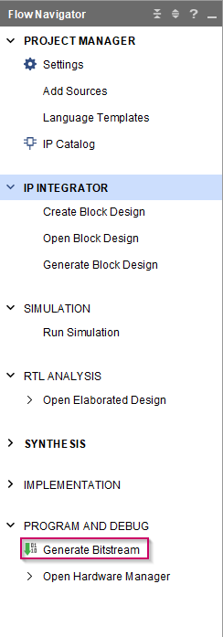
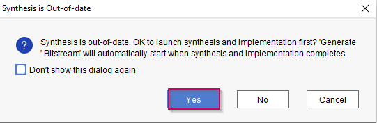
28.Next we need to generate the bit-stream for this hardware design. For that click on Generate Bitstream in the bottom of the left pane. Then click Yes to the pop-up window
29. Wait until the process is finished. Once it is finished, there will be a pop-up window. Click Cancel to that.
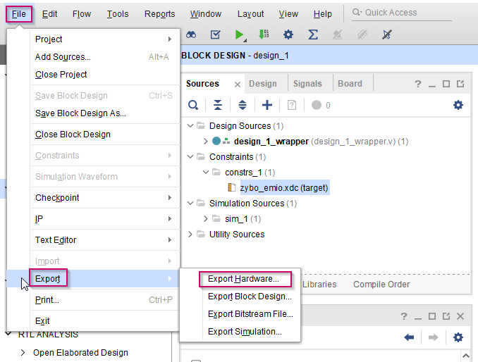
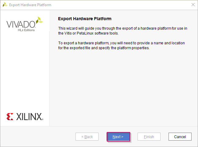
30. Last step is to export the hardware design file. For that, go to File → Export → Export Hardware.
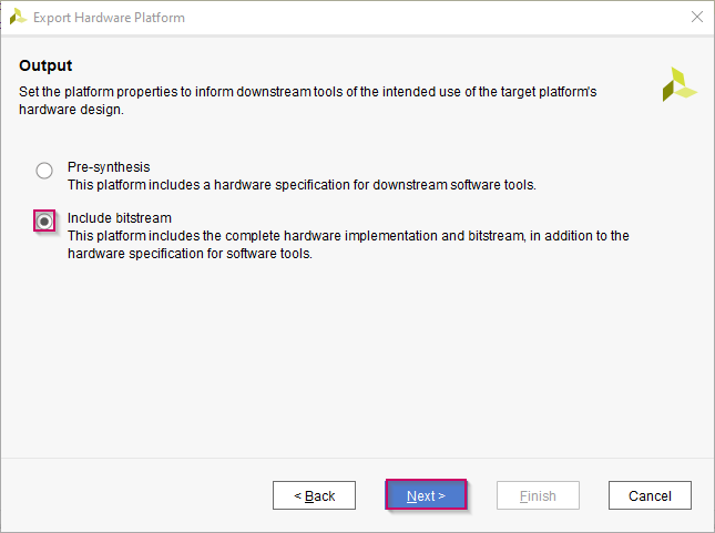
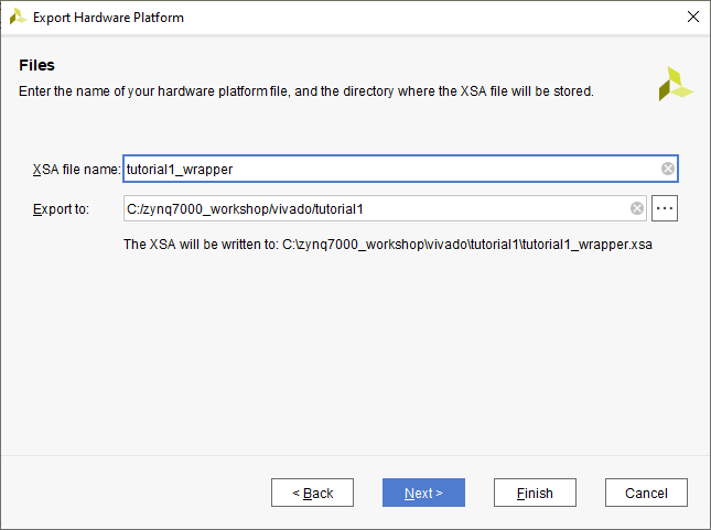
31.Click Next on the wizard. Next, select Include Bitstream from the selection and click Next. Then give a proper name for the hardware design file(XSA). Click Next and at last click Finish
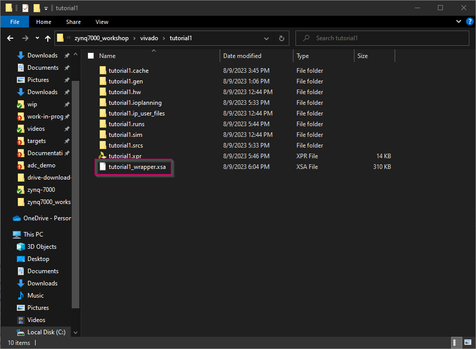
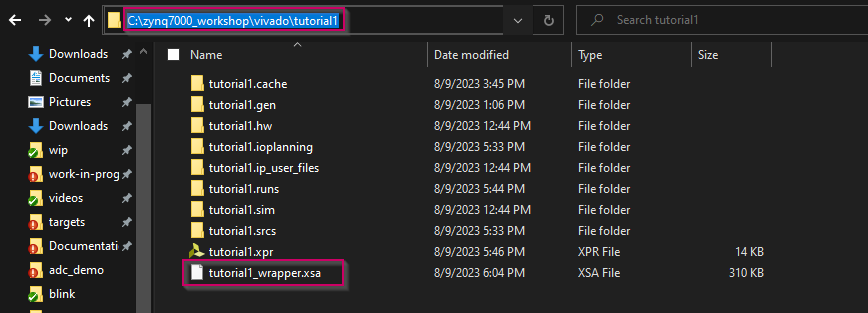
32. You can find the XSA file in the project folder. This will be needed for the Waijung 2 blockset
Create the application project using MATLAB Simulink and Waijung 2 ZYNQ-7000 blockset
1.Open MATLAB and change the current folder of MATLAB to a path where it doesn't contain any spaces.
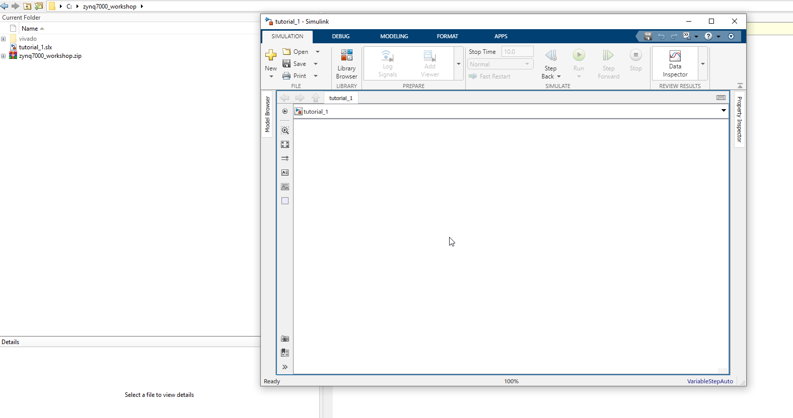
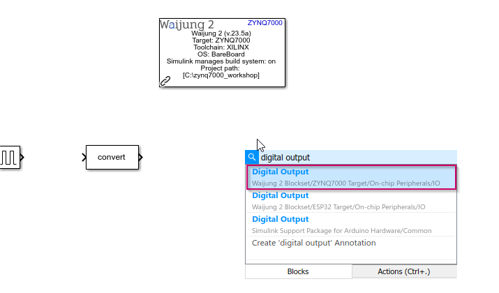
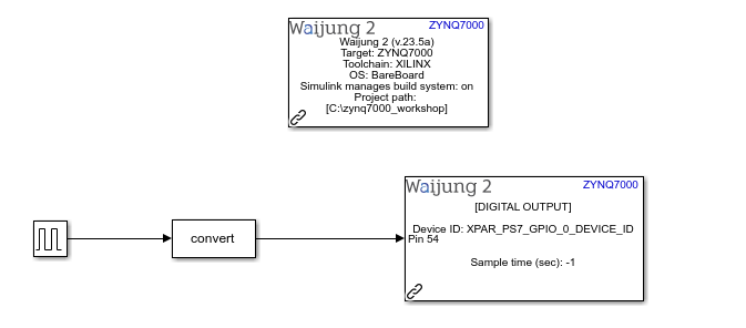
2.Add following blocks to the current Simulink model. To add the blocks, click on a empty white space on the Simulink model and type the block name.
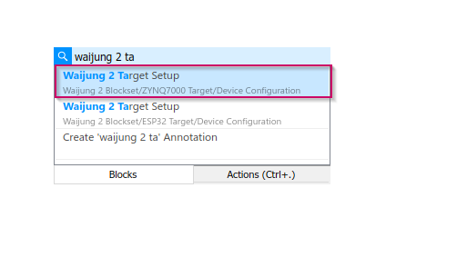
a.Waijung 2 Target Setup
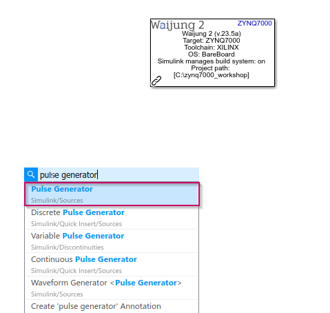
b.Pulse Generator
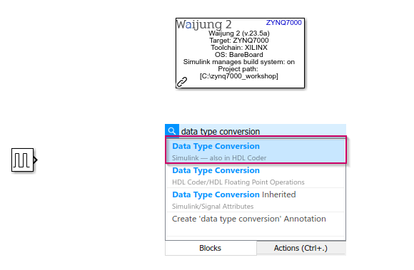
c.Data Type Conversion
d.Digital Output
3.Then, configure the added blocks as follows
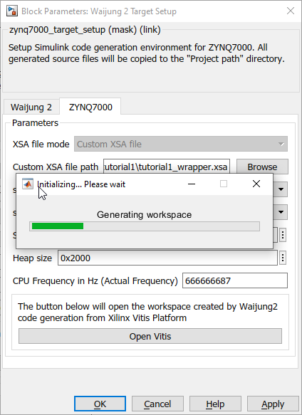
a.Waijung 2 Target Setup
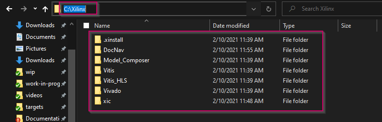
i.Set the Xilinx Tool Path in Waijung 2 tab. This is the path to the folder that you have installed Vivado and Vitis
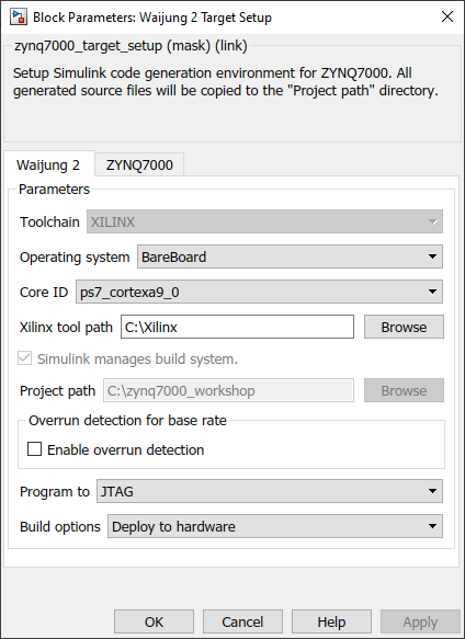
ii.Browse the XSA (hardware design file) in ZYNQ7000 tab that we exported from the Vivado and wait until the process is finished.
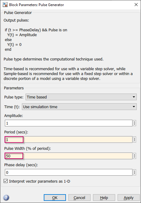
b.Pulse generator
i.Set the Period to 1 and Pulse width to 50 to generate the 1Hz square wave
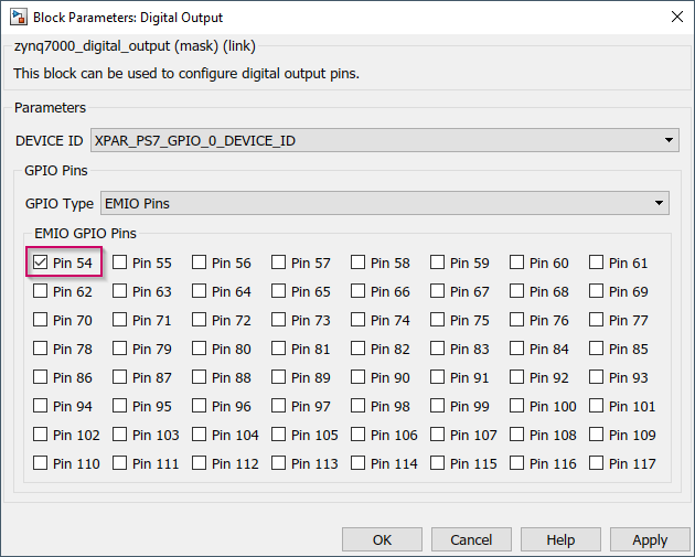
a.Digital output
i.Deselect the default selected Pin 7
ii.Set GPIO Type to EMIO
iii.To select EMIO pin(s), please consider the following steps
1.First consider the EMIO width that you configured in Vivado
2.You have to check the signal name(s) for the EMIO interface. In the schematic in synthesis signal name for each EMIO ports will be GPIO_0_tri_io[0] to GPIO_0_tri_io[n]. So GPIO_0_tri_io[0] always be pin 54 in EMIO pin list in Digital output block. Consider the following examples.
a.If EMIO pin width is 2 in Vivado
i.GPIO_0_tri_io[0] will be pin 54 and GPIO_0_tri_io[1] will be pin 55
b.If EMIO pin width is 5 in Vivado
i.GPIO_0_tri_io[0] will be pin 54, GPIO_0_tri_io[1] will be pin 55, GPIO_0_tri_io[2] will be pin 56, GPIO_0_tri_io[3] will be pin 57 and GPIO_0_tri_io[4] will be pin 58.
i.Since we are going use only one EMIO pin select pin 54
4.Connect the following blocks in the Simulink model
a.Connect the Pulse generator to the Data type conversion block
b.Connect the Data type conversion block to the Digital output block
5.Now the Simulink model is complete. Save the model first. Next we need to download the application to the hardware. To do that,
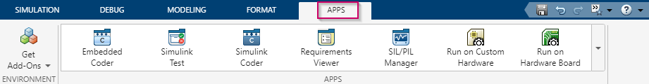
a.Go to the APPS tab in the Simulink model
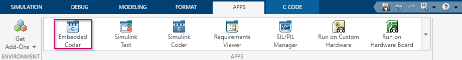
b.Then select Embedded Coder
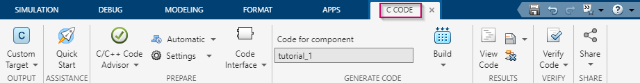
c.Then C CODE tab will appear
d.After that connect the Zybo Z7 board to the computer using the USB cable, connect the Programming port to the USB cable and turn ON the board.
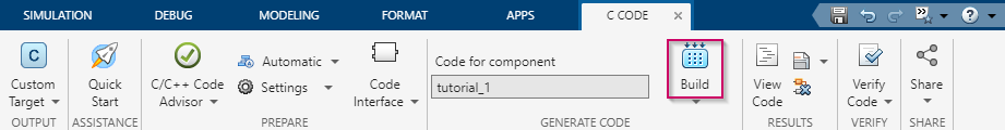
e.Click the Build button in the C CODE tab. Then it will start to build the model, compile and download to the hardware
f.Wait until the process is finished. Once it is finished, the LD0(M14) LED will start to blink in 1Hz frequency
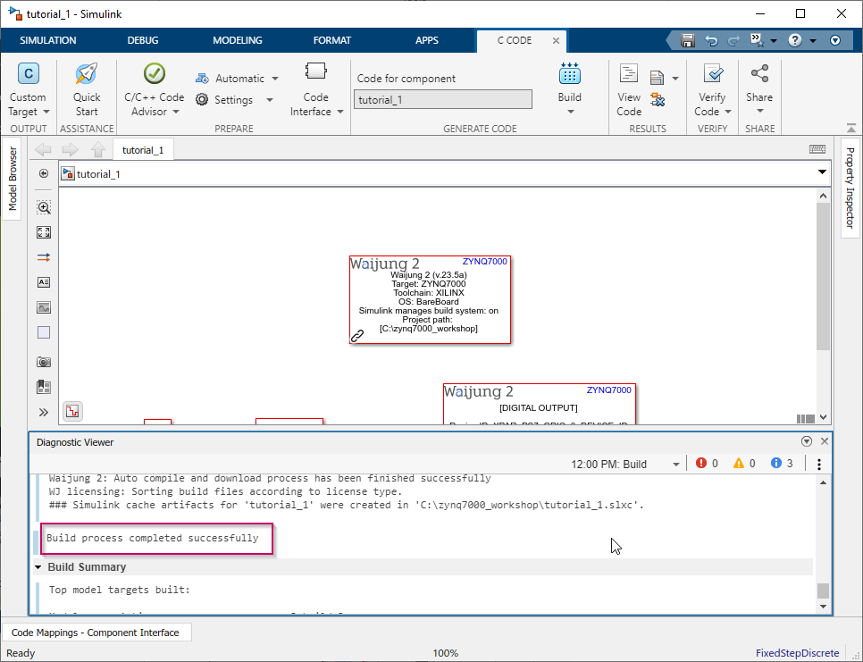
6.The output results
Resources
Simulink model: tutorial_1.slx
XSA file: tutorial1_wrapper.xsa
Vivado project: basic_tutorial1.zip