Introduction
This document will guide you through the process of creating your first program using Waijung 2 for ZYNQ7000. By the end of this tutorial you will be able to,
•Hands-on practice on Vivado design suite basics.
•Understand the fundamentals of Matlab Simulink development environment.
•Understand the fundamental steps in creating a model, building and uploading to the target ZYNQ7000.
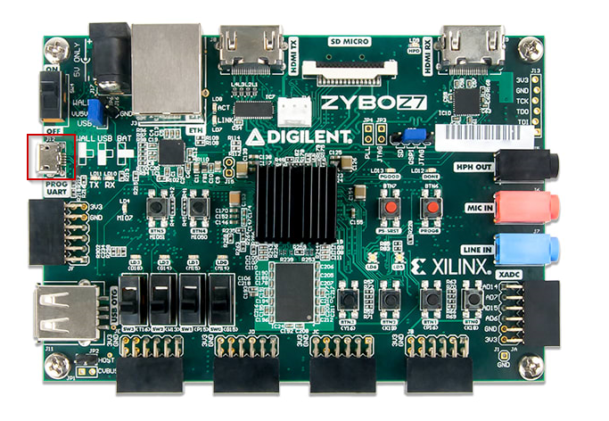
Following documentation is based on Zybo Z7-20 development board.
Required Hardware
You will require the following hardware.
1.a Zybo Z7-20 development board
Required Software
Please refer the Prerequisites section and System Requirements section.
Setup
Before moving forward with the rest of the tutorial, complete the following steps.
1.Download the Waijung 2 block set. Follow the How to get Waijung 2 documentation for more details.
2.Install the Waijung 2 software. Follow the Waijung 2 installation guide for more details.
3.Connect the development board to the computer via the PROG UART USB port and set the boot mode to JTAG in JP5.
Let's Get Started!
The steps below will guide you through the process of creating a simple LED blink example.
Create the hardware reference file using Vivado design suite
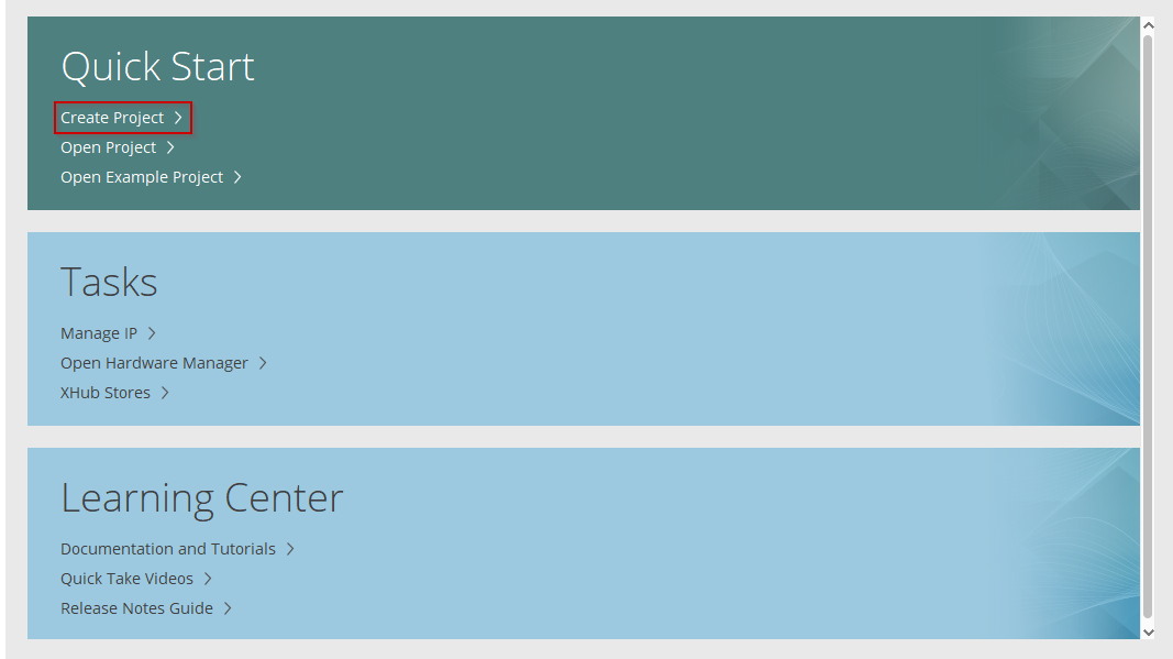
1.Open the Vivado design suite
2.Select Create Project
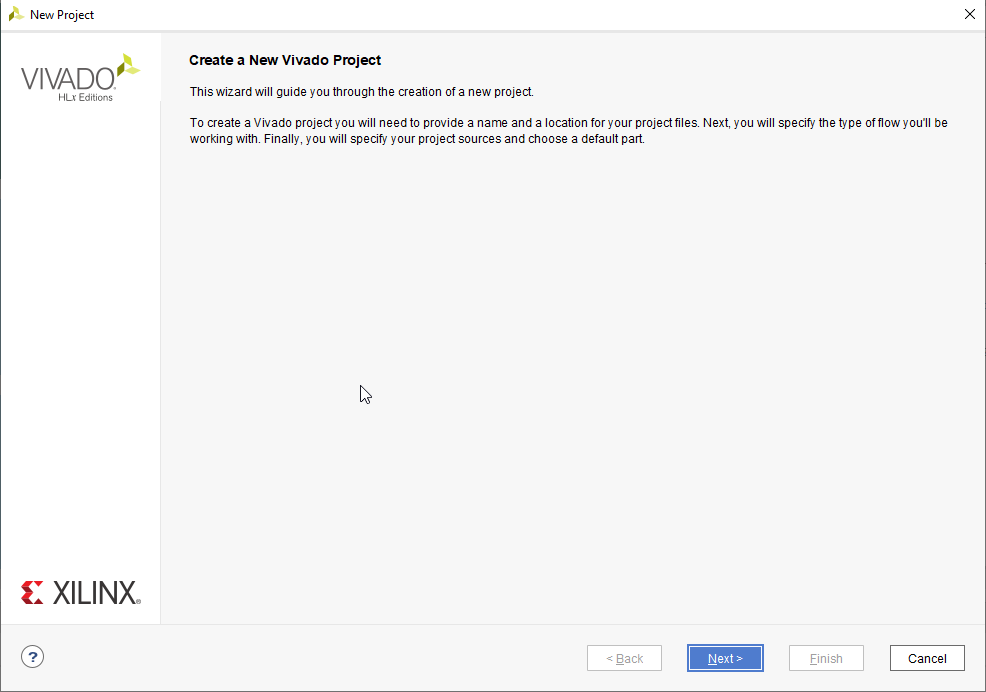
3.Click on Next
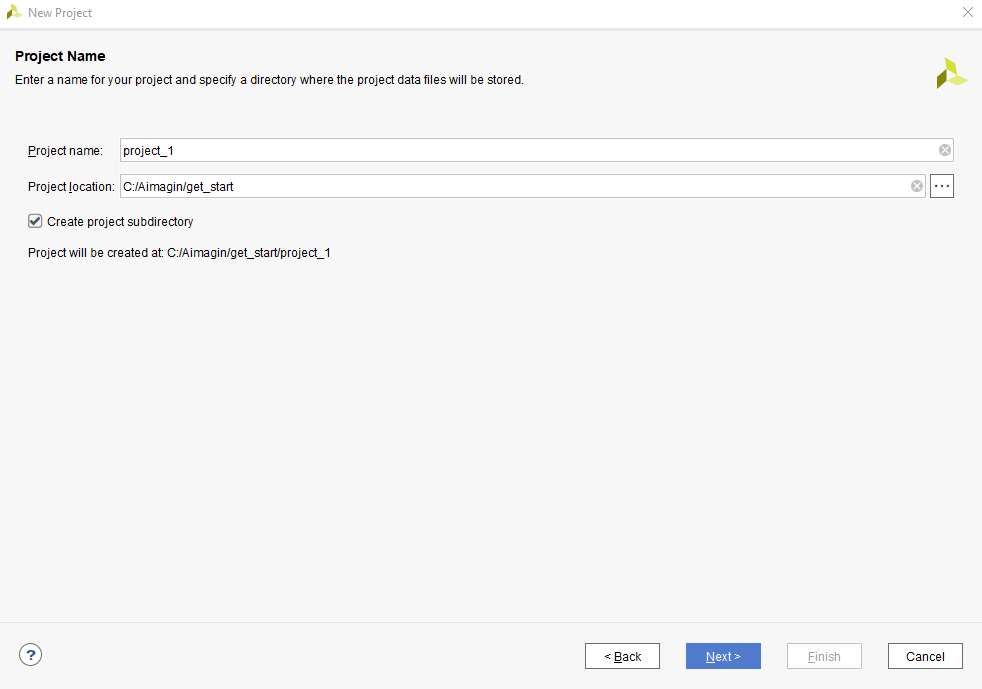
4.Provide a proper name and a location for the project. Click Next to continue.
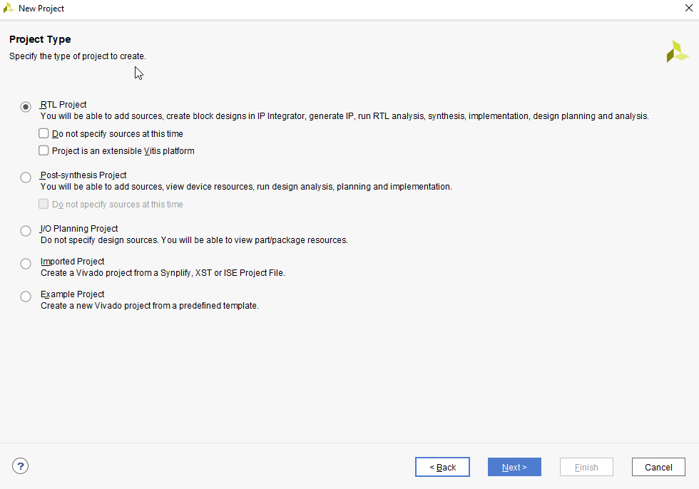
5.Select RTL Project and click Next.
6.Click Next for Add Sources and Add Constraints
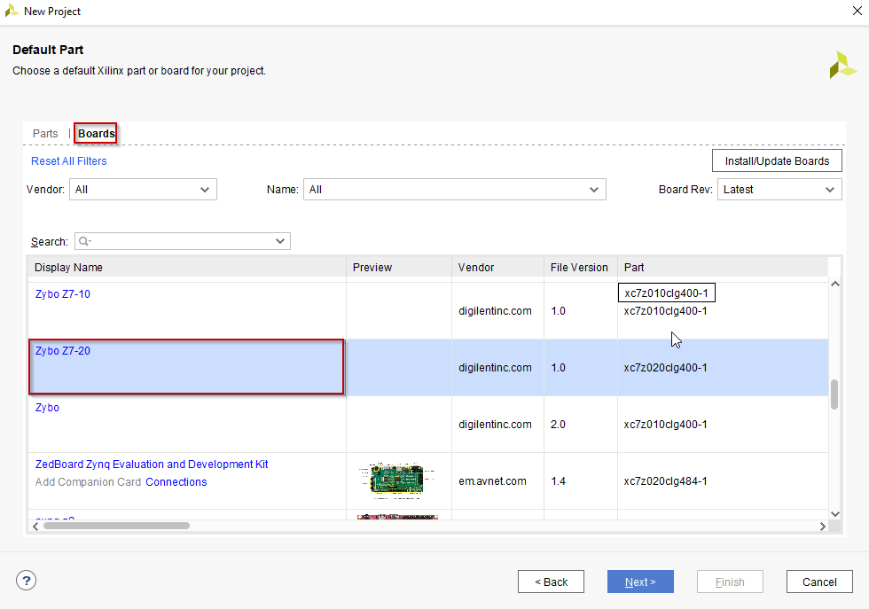
7.Then, select Zybo Z7-20 board under Boards and click Next
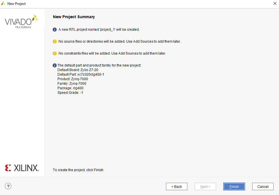
8.At last, click on Finish
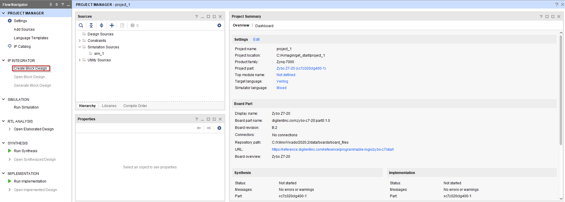
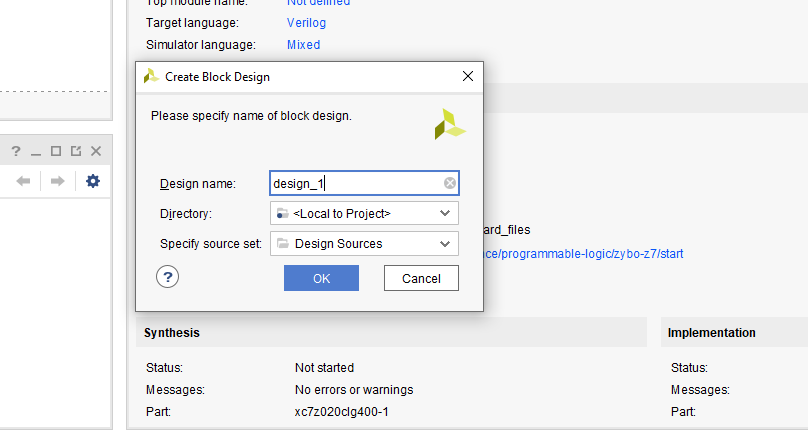
9.Once the project is loaded, go to Create Block Design
10.Click OK to create the block design with the given name
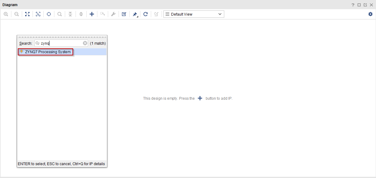
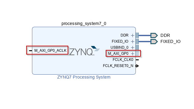
11. Once the blank diagram, click on  or use Ctrl + i to add Vivado IPs to the diagram. Only ZYNQ7 Processing System IP is required for this project. Add ZYNQ7 Processing System IP to the diagram.
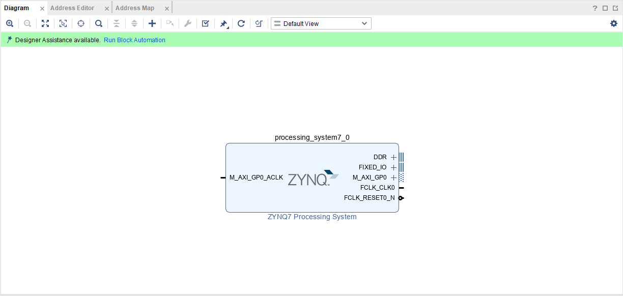
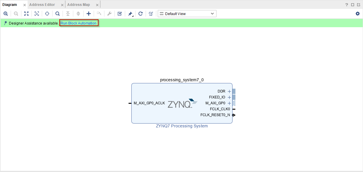
12. Then click on Run Block Automation to configure the IP automatically according to the hardware and click OK.
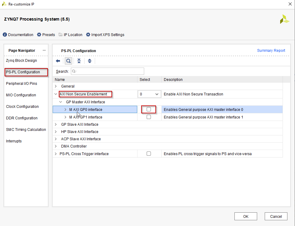
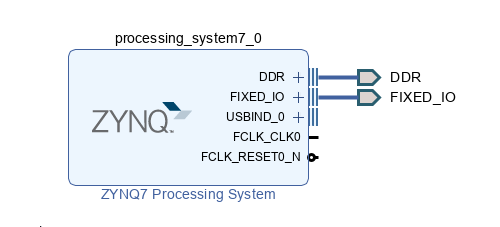
13. Unnecessary ports and interfaces can be removed from the IP. In here, M_AXI_GP0 is not required for this project. To remove it, double click on the IP. Then go to PS-PL Configuration, expand AXI Non Secure Enablement, expand GP Master AXI Interface and disable M AXI GP0. Next click OK
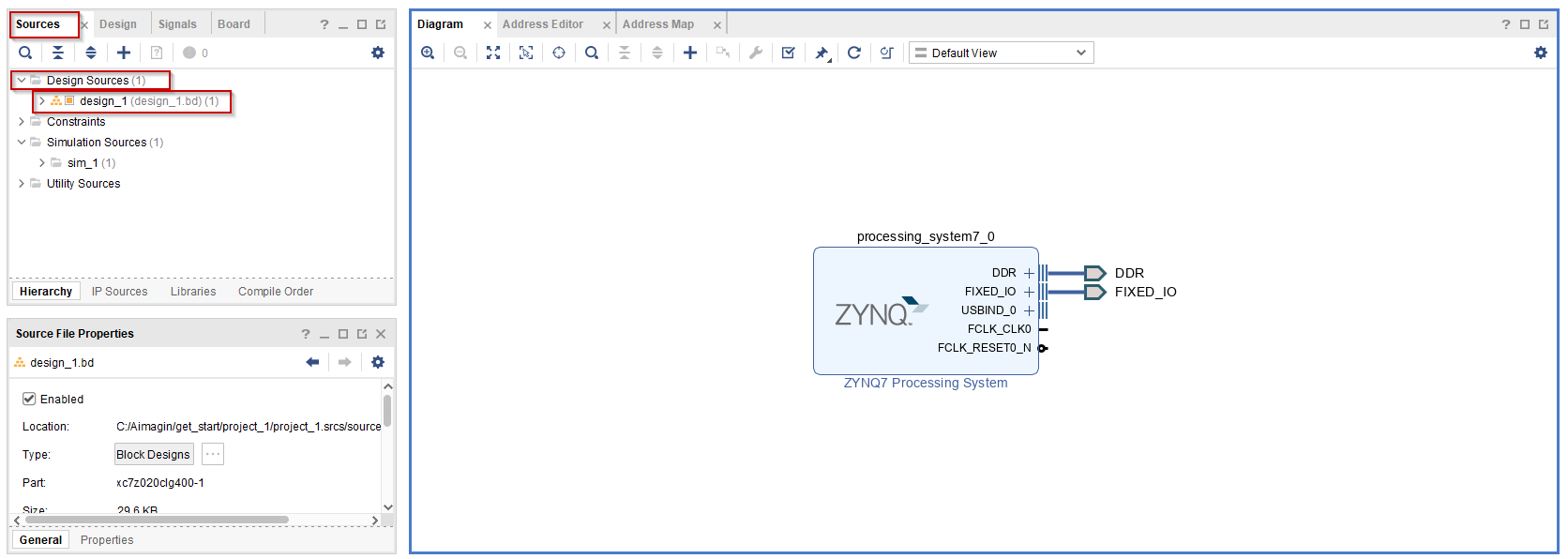
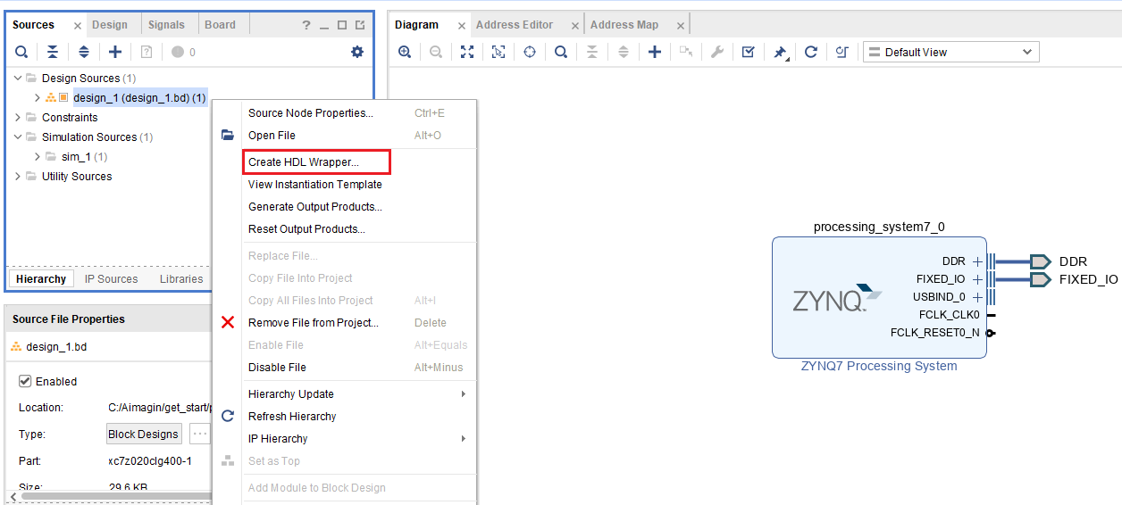
14. Save the block design. To generate the Bitstream, first go to Design Sources under Sources. Then right click on design_1 and select Create HDL Wrapper. Select Let Vivado manage wrapper and auto-update from the selection and click OK
15. Once that process is finished, generate the Bitstream by clicking on Generate Bitstream. Then click Yes to continue.
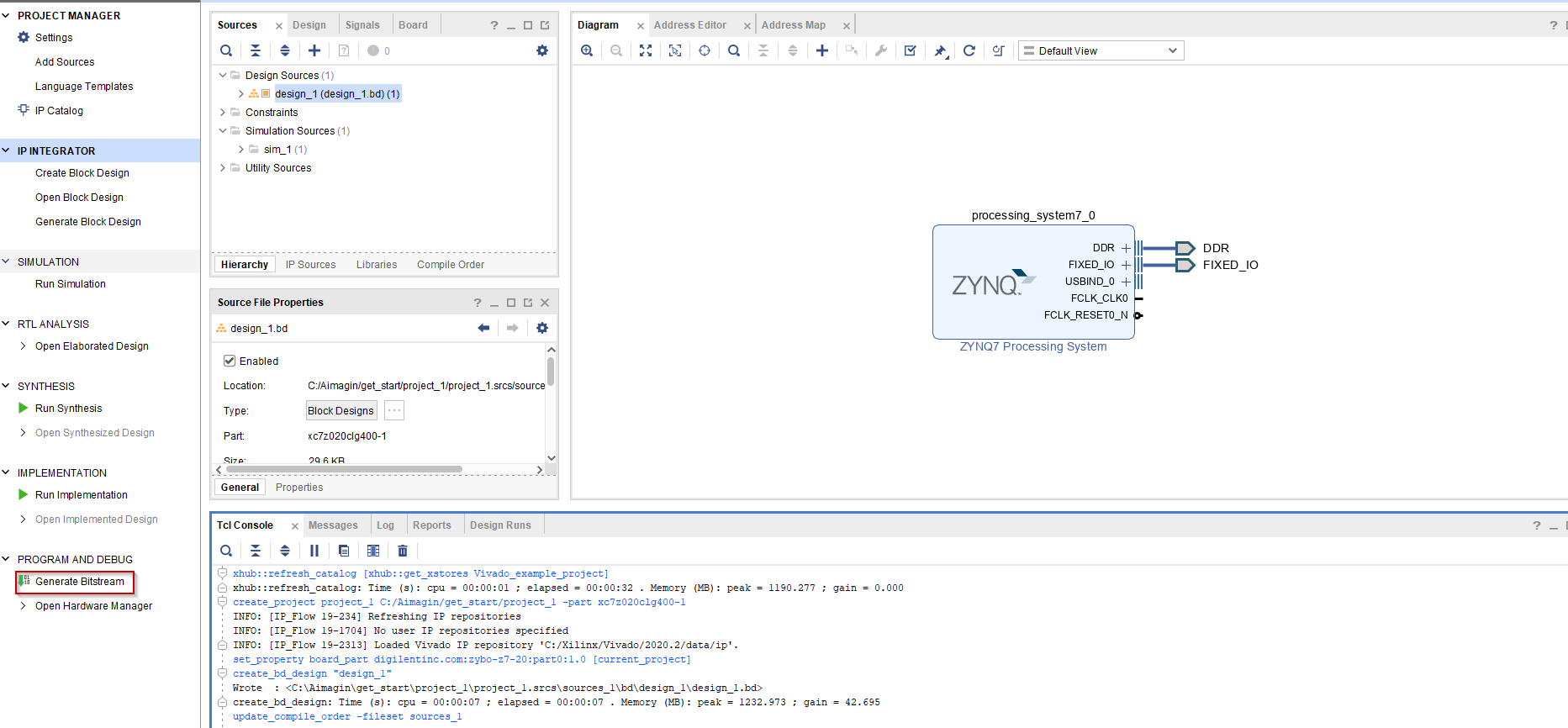
16.Wait until process is finished. Next, the remaining task is to export the hardware design file from Vivado. For that, go to File → Export → Export Hardware
17.Click Next on the wizard. Next, select Include Bitstream from the selection and click Next.
18.Then give a proper name for the hardware design file and the location to export.
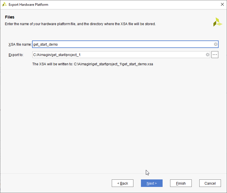
19. Then click on Next and click Finish.
Create the Simulink Model
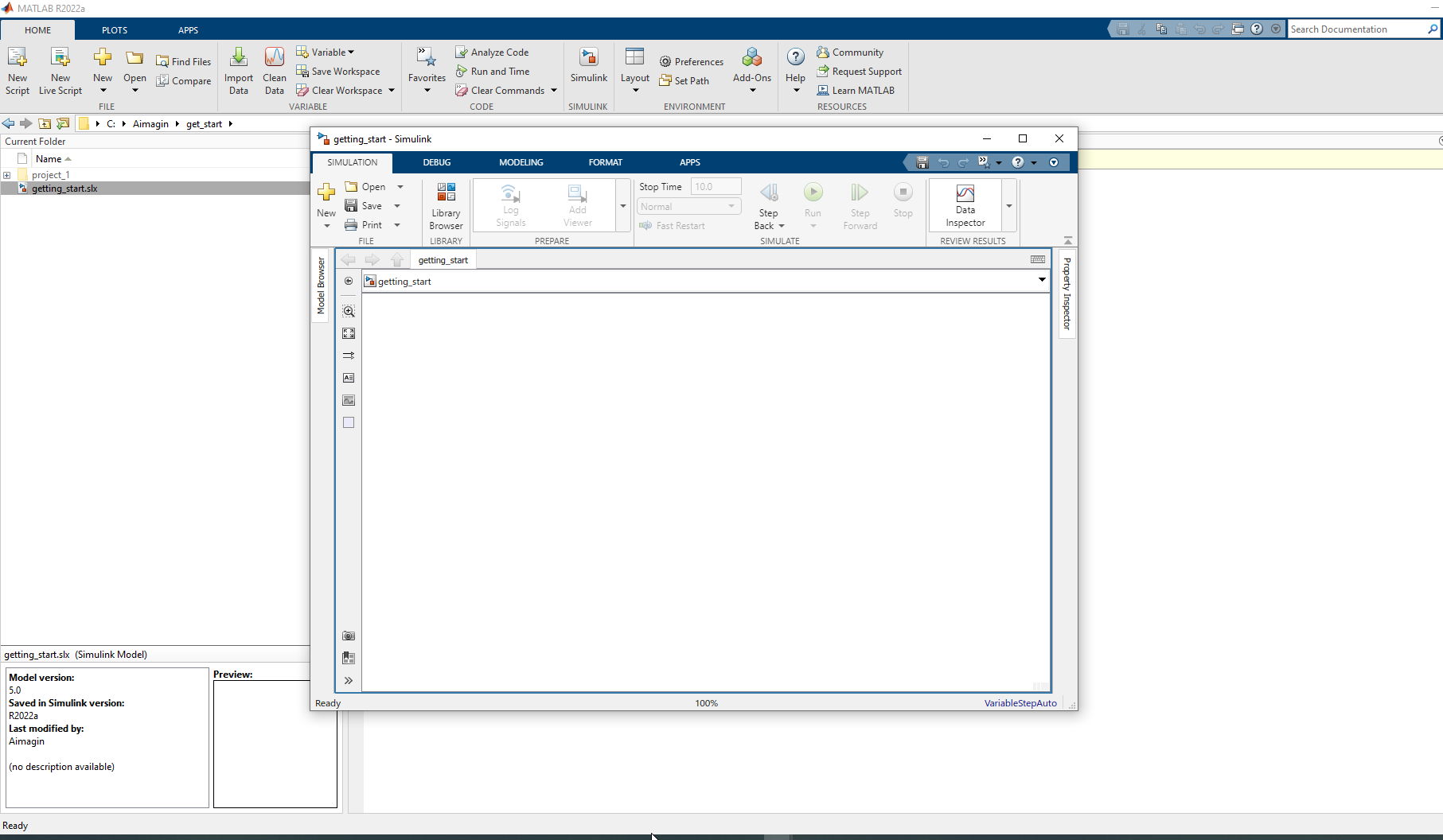
1.Change the current folder of Matlab to a path where it doesn't contain any spaces. Create a blank Simulink model and save it. Make sure the model name does not have spaces in it.
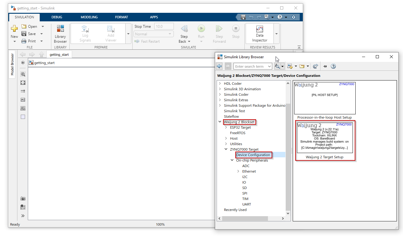
2.Next we will import the blocks related to this example. First, the Waijung 2 target setup block should be imported to the model. It is mandatory to add this block to your Simulink model files that intend to use Waijung 2 software. After the Waijung 2 installation, the block set will be available in the Library Browser. You can use the library browser to import Waijung 2 blocks to your workspace.
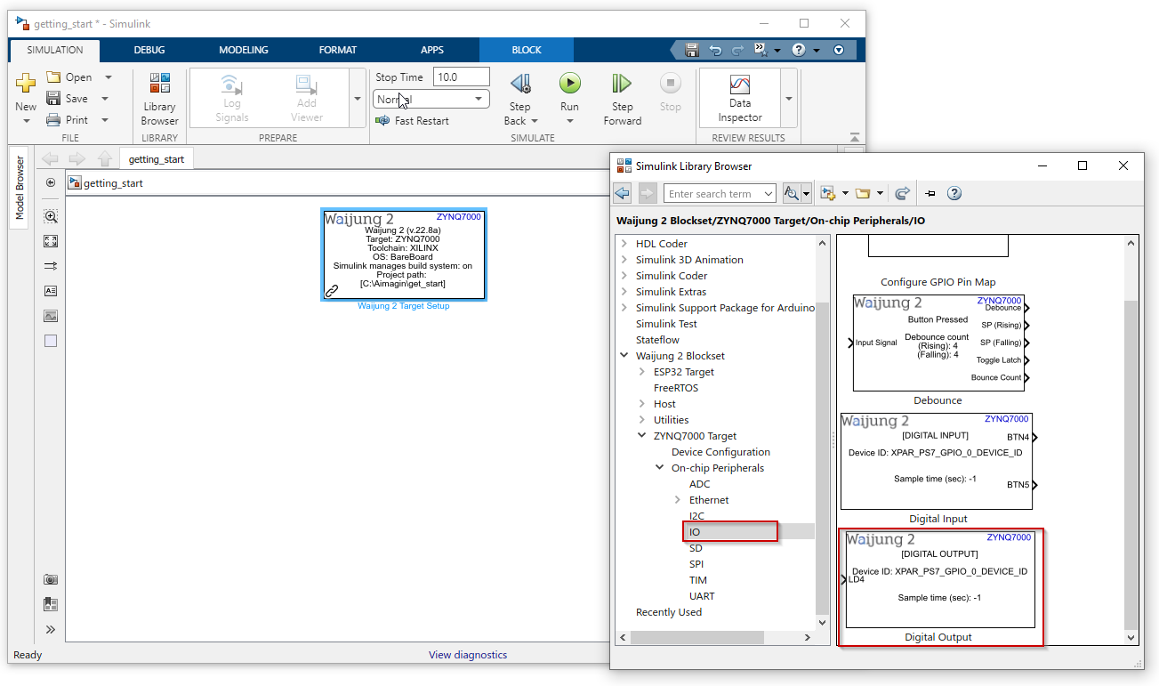
3.Next, import the following blocks to the model by following the same procedure explained in the previous step.
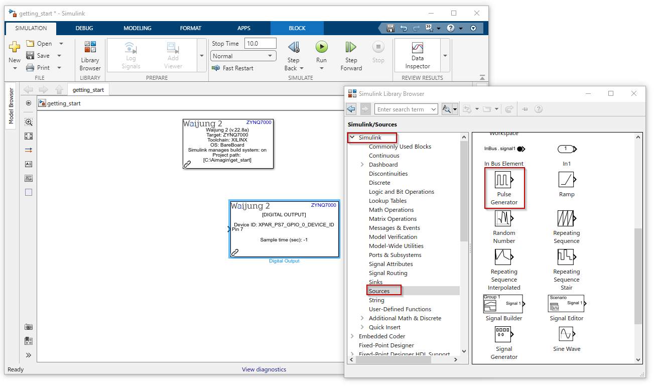
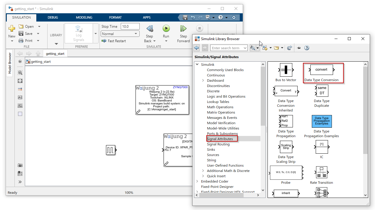
4.Connect the blocks as below
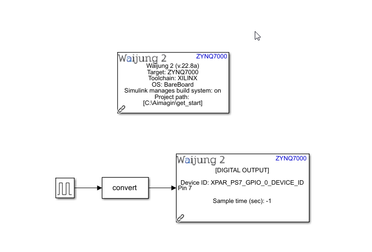
5.Double click on the block to open the block mask of each and every block. The block mask can be used to configure the block according to your preference. Open the block mask of each block in the above model and change the following configurations.
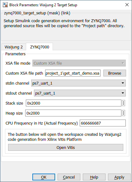
a.Waijung 2 Target Setup block mask
Change the Xilinx tool path accordingly
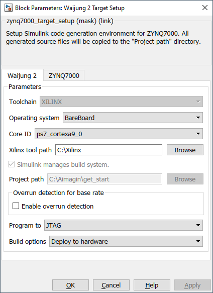
Browse the hardware design file which we exported from Vivado and wait until the workspace is created using Xilinx tools
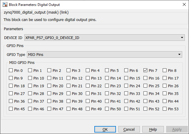
b.Digital Output block mask
On-board LED LD4 which is connected to MIO7 is used here.
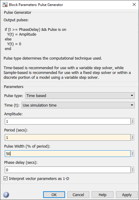
c.Pulse generator block mask
6.Save the Simulink model file
Build and download the Simulink model to the target
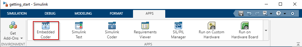
1.Finally, we can start building the program. Go to APPS tab and click Embedded Coder. After the C CODE tab opens, click the drop down menu and click Build. Do NOT click Generate Code.
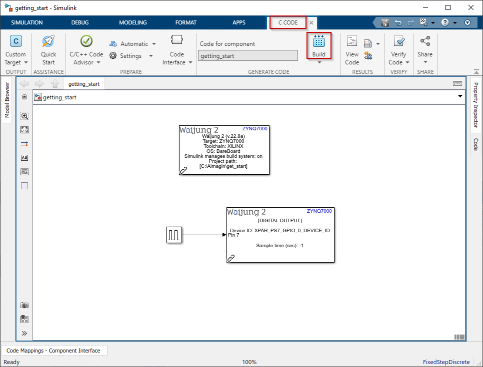
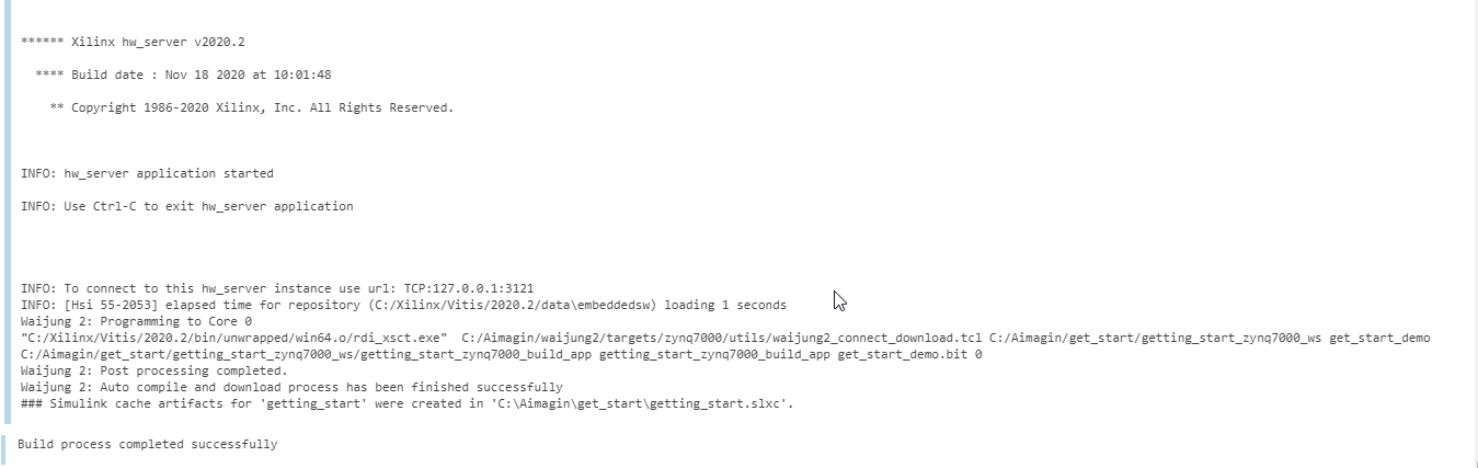
2.Once you click Build, Waijung 2 will start generating C code for your model and upload it to the board. You will be able to monitor the progress using the Diagnostic Viewer. Wait for the build process to complete.
Results
The LED will start blinking at a frequency of 1 Hz.
Additional Information
In case the user wants to monitor run time serial data, free serial monitor software such as PuTTY and Docklight can be used. Please make sure the correct COM Port and the BaudRate of 115200 is used.