Design overview
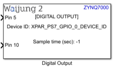
Digital output block appearance in a Simulink model,
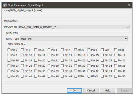
Digital output block mask overview,
Digital Output Block input interfaces
Name |
Type |
Range |
Description |
Pin <x> |
Default: Any data type The data type of the port can be changed using Configure GPIO Pin Map block |
Expected values 0 or 1 |
<x> represents the selected pin number. For each selected pin in the mask, a separate port will be created. |
Digital Output Block output interfaces
Name |
Type |
Range |
Description |
N/A |
|
|
|
Digital Output Block behavior
Digital output block can be used to configure GPIO pins via MIO and EMIO interfaces. Using this block the pins can be configured to work in either interrupted or polled mode. The pins are labelled from 0-117. Pins 54-117 are connected through the EMIO interface and have to be mapped during the hardware design stage using Vivado Design Suite. To assign a custom label for a certain pin for convenience, Configure GPIO Pin Map block can be used. This block can also be used to assign the port data type for each individual pin.
Digital Output Block configuration
Configuration Parameter |
Selectable Option/Value |
Description |
|
DEVICE ID |
XPAR_PS7_0_DEVICE_ID |
Depending on the peripheral availability in your hardware design created using the Vivado Design Suite, available device-ids will be shown. |
|
GPIO Type |
MIO Pins |
EMIO Pins |
Select the GPIO interface. Depending on the selected interface, respective configurable pins are shown. In the case of EMIO, the pins displayed on the block mask may or may not be available in your actual hardware design. |
Pin <x> |
On |
Off |
The pins to be configured using the block can be selected by toggling the check boxes. |
Digital Output Block limitations
The known limitations associated with the block are:
•By default, in the block mask display all the pins (0-117) are available for the user to configure. However, depending on the hardware design (XSA file provided in the model Target Setup Block) some pins might not be available for configuration.
•Depending on the hardware development board, some pins could be hardwired as either input or output. Waijung 2 block set does not have the ability to acquire this information and therefore, will not be able to indicate these pins in the block mask.
Troubleshooting
Typical application
Several demo files are provided at:
[<waijung2 installation directory>\waijung2\targets\zynq7000\demo\gpio_demo]
To load the model file run the following commands in the Matlab Command Window:
•Demo 1: waijung2.openDemoInCurrentFolder('zynq7000', 'gpio_demo1')
•Demo 2: waijung2.openDemoInCurrentFolder('zynq7000', 'gpio_demo2')
•Demo 3: waijung2.openDemoInCurrentFolder('zynq7000', 'gpio_demo3')
•Demo 4: waijung2.openDemoInCurrentFolder('zynq7000', 'gpio_demo4')