Designing Simulink model for derived RC Circuit Differential Equation
Use Time Constant
The Figure 2 shows the schematic illustrating the wiring connections of RC circuit.
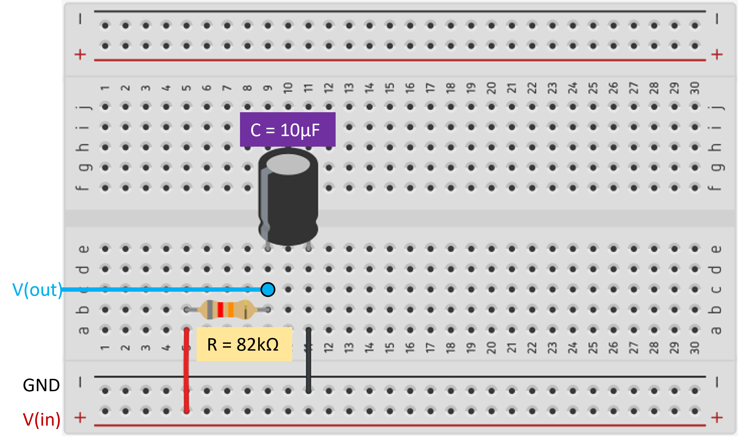
Figure 2: Schematic Representation of the Physical RC Circuit
Step 1: Get derived Differential Equation (Time domain)
Step 2: Create the Simulink model
Use following blocks:
•For Input : Step
•To create differential equation : Sum,Gain and Integrator
•For Output : Scope
Simulink Model: rc_differential_equation.slx
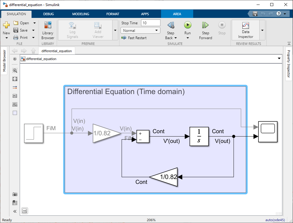
Figure 3: Simulink Model of the Derived RC Circuit Differential Equation(Time domain)
Why use 'Integrator' block instead of 'Differentiator' block?
The reason is that the "Differentiator" block in Simulink is used to approximate the derivative of a signal with respect to time, while the RC circuit model requires integration to obtain the voltage across the capacitor.
In the RC circuit model, we have a capacitor voltage equation that involves integration:
To solve this equation in Simulink, we use the "Integrator" block, which performs numerical integration to obtain the capacitor voltage (Vout) from the derivative .
On the other hand, the "Differentiator" block in Simulink approximates the derivative of an input signal. It doesn't perform numerical integration, which is what we need in the RC circuit model.
Step 3: Run Simulation and Open Scope for the results
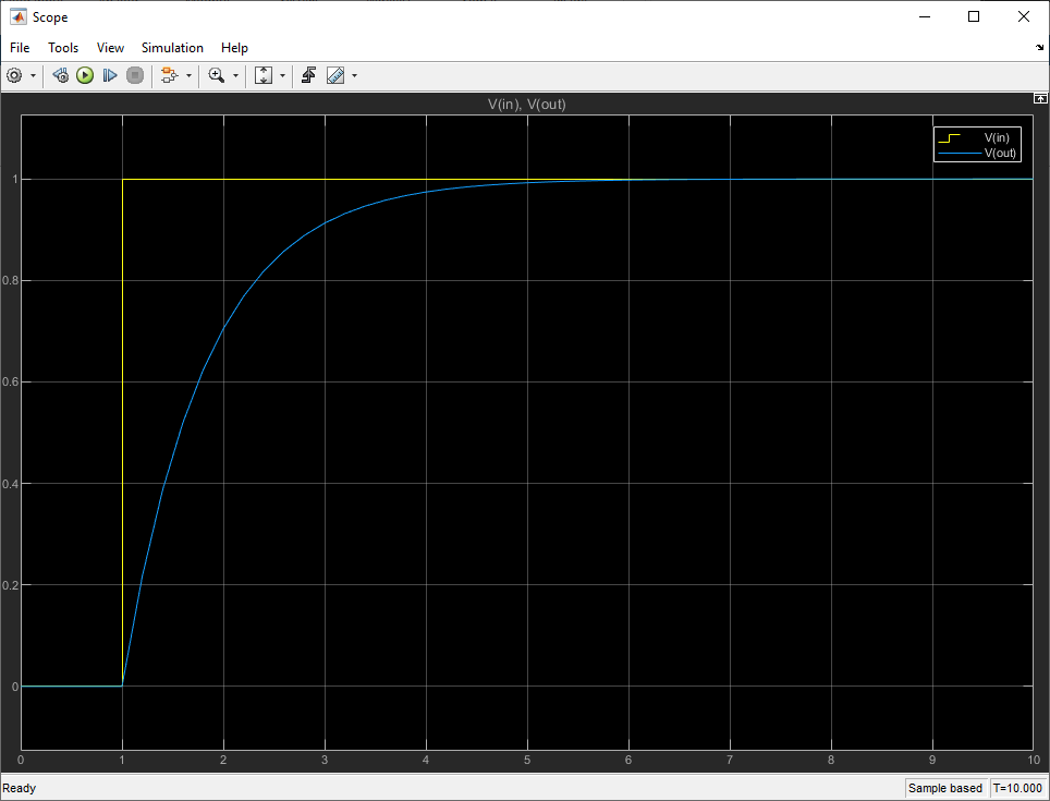
Figure 4: Simulation Results of the Derived RC Circuit Differential Equation(Time domain) in Simulink
In the Simulink simulation of the RC circuit (Figure 4), we observed the expected behavior of the capacitor voltage (Vout) over time. With an initial voltage of zero and a step input applied at one second, the voltage across the capacitor increased exponentially before settling at a final value of 1 volt. This behavior is consistent with the charging response of an RC circuit, where the capacitor gradually charges up to the step input voltage. The time constant (RC) of approximately 0.82 seconds played a crucial role in determining the rate of charge. The Simulink model successfully demonstrated the transient response of the RC circuit, confirming the validity of the derived differential equation representation.
Designing Simulink model for derived RC Circuit Transfer Function
Step 1: Get derived Transfer Function (Frequency domain)
Step 2: Create the Simulink model
Use following blocks:
•For Input : Use same Step block from Differential Equation model
•To create transfer function : Transfer Fcn
•For Output : Use same Scope block from Differential Equation model and add another input port
Use Time Constant
Simulink Model: rc_transfer_function.slx
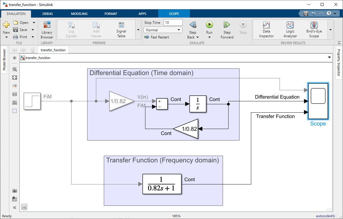
Figure 5: Simulink Model of the Derived RC Circuit Transfer Function (Frequency Domain)
Step 3: Run Simulation and Open Scope for the results
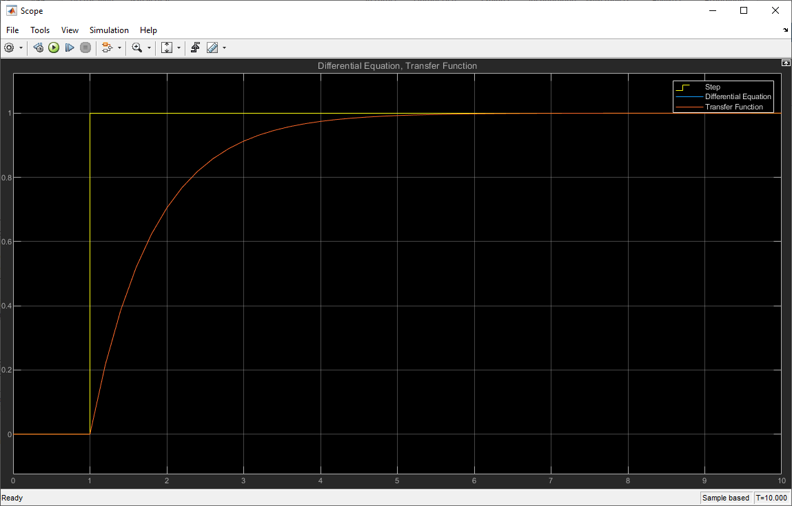
Figure 6: Simulation Results of the Derived RC Circuit Transfer Function (Frequency Domain) in Simulink
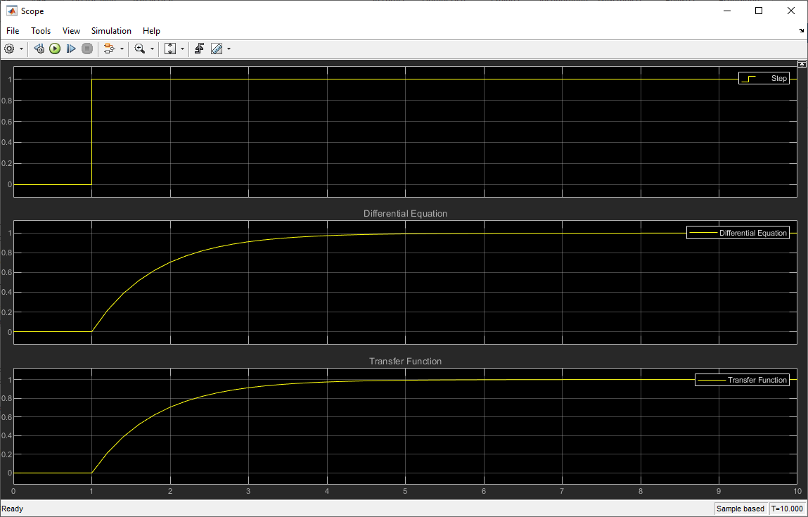
Figure 7: Comparative Analysis of Simulation Results between Derived RC Circuit Differential Equation (Time domain) and Derived RC Circuit Transfer Function (Frequency Domain) Using Simulink Model