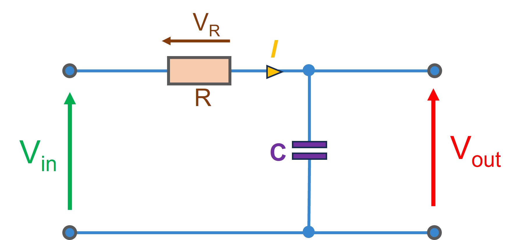
To develop the mathematical model of the RC circuit, we need to derive the differential equation that describes its behavior. Let's consider a series RC circuit for this example.
The voltage across the resistor (VR) and the voltage across the capacitor (Vout) add up to the input voltage (Vin).

Figure 1: Schematic Diagram of the RC Circuit Configuration
Step 1: Applying Kirchhoff's voltage law (KVL) to the series RC circuit, we can write:
Step 2: Expressing the voltages using Ohm's law :
Step 3: Substituting I with :
Step 4: Rearranging the equation and dividing both side with RC
Step 5: Defining the time constant
Step 6: Differential equation (Time domain)
Step 7: Finally, converting the differential equation into a transfer function representation by taking the Laplace transform:
Where s is the Laplace variable and is the initial voltage across the capacitor.
Simplifying the equation further and solving for , we get:
Step 8: Transfer Function (Frequency domain)
This is the transfer function representation of the RC circuit. It relates the input voltage Vin(s) to the voltage across the capacitor Vout(s) in the frequency domain.
The derived differential equation and transfer function provide a mathematical description of the RC circuit's behavior and can be used for further analysis, control system design, and simulation in tools like Simulink.