Project description
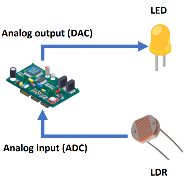
In this project you will design a control algorithm that can be used to control a LED depending on the surrounding light level detected by a LDR sensor. You will use a software-only simulation to verify that it performs correctly.
Learning objectives
In this tutorial you will learn:
1.How to model reading LDR in Simulink
2.How to model driving LED through LDR input in Simulink
3.How to use Simulink Dashboard components to aid visualization
Hands-on
Software in the Loop (SIL) simulation
Tips and tricks to build SIL model:
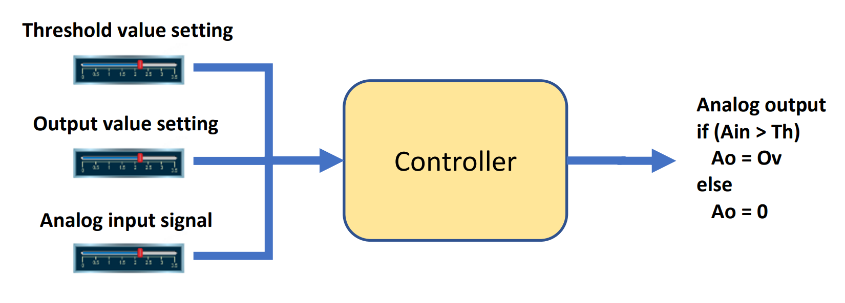
1.Start with a simple control algorithm, where you can set the following parameters:
a.A threshold value setting: values should be between 0 and 4095
b.An analog output (LED brightness) value setting: values should be between 0 and 255
c.An analog input (from LDR sensor) signal: values should be between 0 and 4095
2.Import 'Slider' block from Library Browser to control the three parameters as stated above.
3.For visual enhancement, you can add 'Gauge' from the Library browser for Threshold and Analog Input setting. For Analog Output, you can use a 'Dashboard Scope'.
4.The controller is to compare the analog input signal with the threshold setting. If the analog input signal is greater than the threshold then output the analog output setting to the analog output, otherwise output 0 to the analog output. Build these 2 operating modes using a Stateflow chart.
5.To view the simulation in real-time, go to Run > Simulation Pacing > Enable pacing to slow down simulation
Final result (click to view video):
After completing the project, continue building your knowledge with an exercise.
Exercise
To build this project further:
1.Modify the model such that the device has 3 operating modes instead of 2:
Operating mode |
Analog output |
Analog input |
On |
Any value up to 255 |
Does not matter |
Auto |
Any value up to 255 |
Analog input > Set threshold |
0 |
Analog input ≤ Set threshold |
|
Off |
0 |
Does not matter |
2.Add a 'Rotary Switch' to use as a mode selector to select the operating modes, and modify the control algorithm accordingly.
Project file: SIL file
Solution to exercise: SIL file