|
Project 5: Temporary traffic light controller (with automatic distance sensor) |
Scroll Prev Top Next More |
Project description
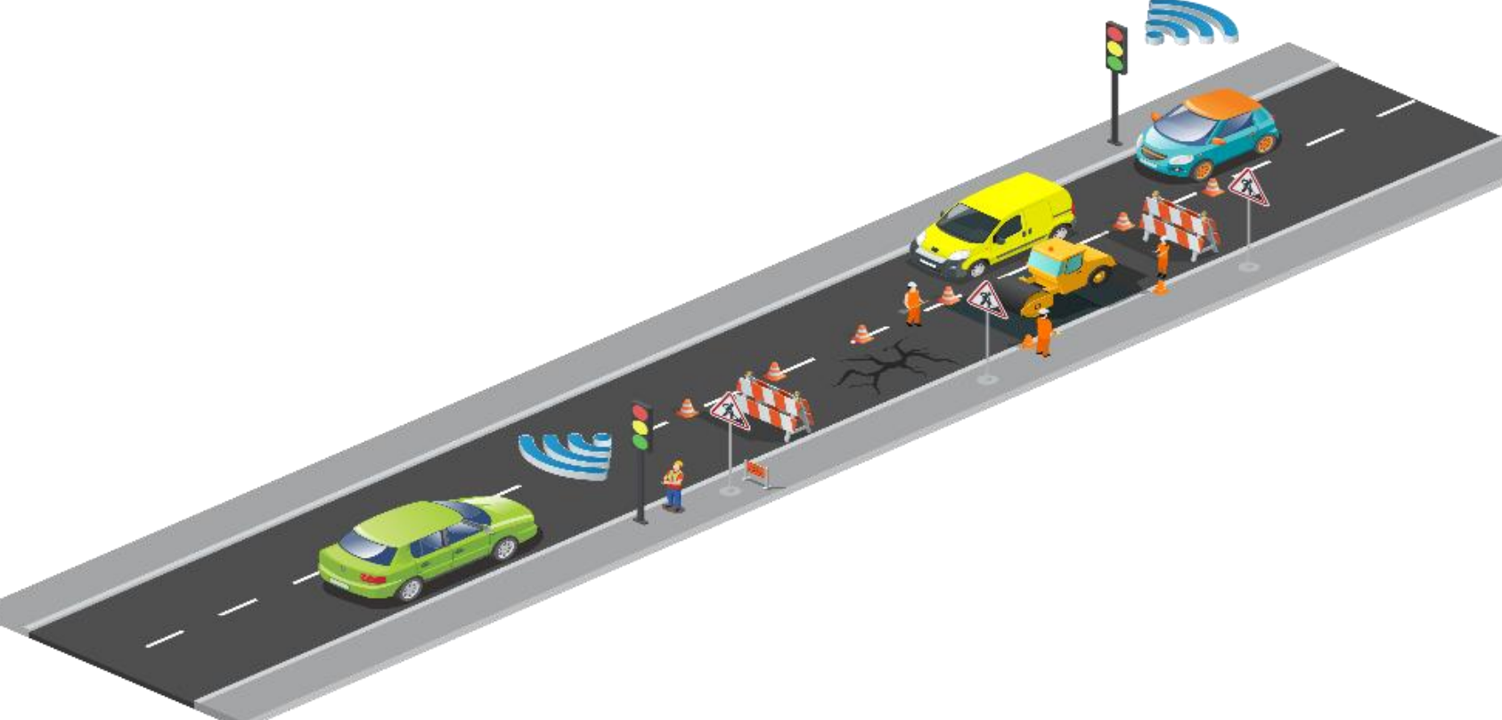
1.In Project 4, you improved the system in Project 3 by adding a dip switch to allow officers to control traffic more effectively. However, this system also requires a person to manually change the status of the switch to control traffic, which is still inconvenient, especially during night hours.
2.In order to facilitate car users and reduce the workload of the officers, improve the system developed in Project 4 by adding distance sensors. In the event that there is no car on one side while cars are waiting on the other side, signals from distance sensors should immediately turn the other side green.
3.Use 3 digital input switches to control 5 working modes as follows:
a.000 - Mode 0: Red light ON for both set 1 and set 2.
b.010 - Mode 1: Green light ON for set 1 (until turned off), Red light ON for set 2. Allow a time delay of 10 seconds before green light changes to yellow after status of the switch is changed.
c.001 - Mode 2: Green light ON for set 2 (until turned off), Red light ON for set 1. Allow a time delay of 10 seconds before green light changes to yellow after status of the switch is changed.
d.011 - Mode 3: Runs automatically according to the specified time as developed in Project 3
e.1xx - Mode 4: Sensor mode (first digit being 1 means that sensor is ON) - the system must work by using signals from the sensor to measure distance and controlling the traffic lights accordingly.
Note:
1.If at any time there is a car detected only on one side, Sensor 1 and 2 can turn ON and OFF accordingly.
2.In the event that there are cars on both sides, both sensors will be turned ON and the system will be in Mode 111. In that case, the system should run automatically according to the specified time like in Mode 011.
Learning objectives
In this tutorial you will learn:
1.What is I2C
2.How to interface with a distance sensor using I2C
3.How to use Stateflow to model complex control systems
4.Applications of traffic light control
Required hardware
No. |
Item |
Picture |
Quantity |
1 |
ESP32 with USB cable |
|
1 |
2 |
Protoboard (830 points) |
|
1 |
3 |
Jumper Wire Male-Male |
|
22 |
4 |
Red 5mm LED |
|
2 |
5 |
Amber 5mm LED |
|
2 |
6 |
Green 5mm LED |
|
2 |
7 |
Resistor 220 Ohms |
|
9 |
8 |
USB Wi-Fi dongle (only necessary if you need to use External Mode in WiFi AP configuration) |
|
1 |
9 |
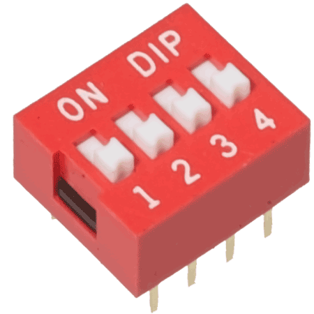
Dip switch (4 pins) |
|
1 |
10 |
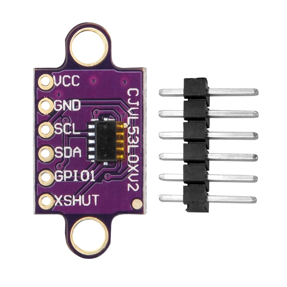
Time of flight distance sensor (product code: VL53L0/1XV2) |
|
2 |
Hands-on
Software in the Loop (SIL) simulation
Tips and tricks to build SIL model:
1.Building on from Project 4, the difference is that an additional sensor working mode has been added (as shown in Item 3 of Project Description). Add this additional working mode to the Stateflow Chart from Project 4 that already consists the previous 4 working modes controlled by two switches
2.Keep in mind that this fifth working mode should only be activated when the sensor is switched ON, thus the third switch can be purely responsible for this fifth mode
3.A separate "Sensor" Stateflow sub-chart will be needed in addition to the already existing "Automatic" and "Manual" sub-charts from Project 4
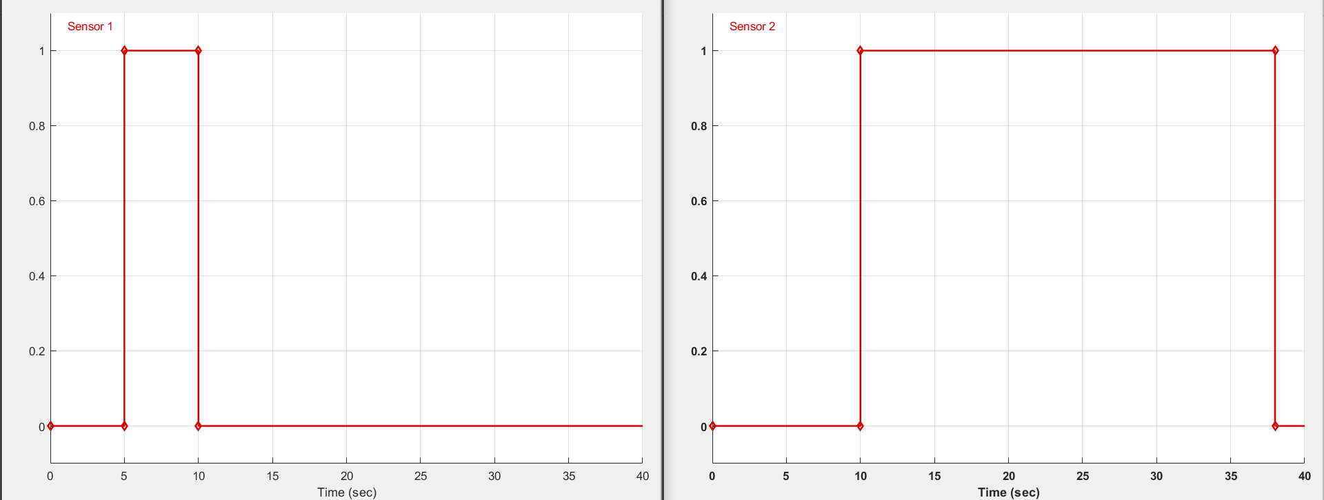
4.To test the system in sensor mode, you may use the following sample situation:
a.Start with no car on either side
b.At T = 5 seconds, 1 car arrives at Set 1. Sensor 1 turns ON
c.At T = 10, 3 cars arrive in a row at Set 2. Sensor 2 turns ON
d.Assume each car in close range of the sensor will cause the sensor to be activated for 5 seconds
e.Once one side turns red, you'll need to make sure there's sufficient time for the cars to pass and get to the other side before the other side turns green. Assume that this time delay is 10 seconds.
5.To test sensor mode as described, use Signal Builders in Simulink to validate the proper working of your model as shown below:
6.Set conditions to transition between 'Manual' and 'Sensor' sub-charts, and also between 'Automatic' and 'Sensor' sub-charts. You will need to account for several possible combinations.
Hardware in the Loop (HIL) simulation
Hardware setup
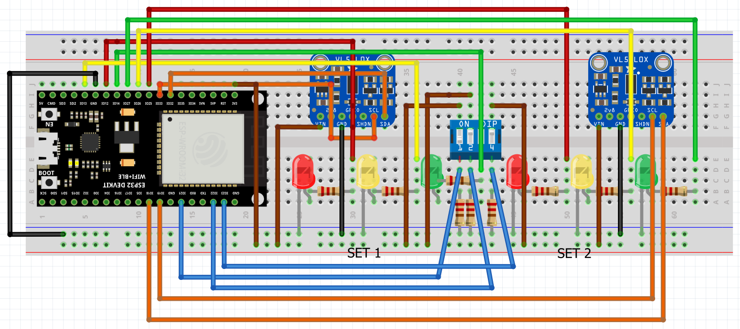
The most important part of building the HIL model for this project is to replace Signal Builders that were used for the SIL model with actual I2C modules.
What is I2C?
Inter-Integrated Circuit (I2C) is the most widely used serial communication protocol that can establish communication between two or more ICs (integrated circuits). It can provide robust communication between a Master (a microcontroller, in our case the ESP32) and a Slave (a peripheral device, in our case the two VL53L0/1XV2 distance sensors).
We would like to use the I2C protocol so that the ESP32 can read values from the distance sensors and then control the circuit accordingly. For our application, if there is a car detected in close range (we will need to define this close range), then green light should be turned ON automatically.
To configure a slave device, we need to register it and then read data from it. There are many devices that can be communicated with through the I2C protocol, so every device has its unique addresses that need to be inputted for setup, in order to let the device know that we are trying to communicate with it.
Generally, the procedure for the Master to read data from the Slave is:
Master sends a START condition and addresses the Slave
Master sends the requested register to read from Slave
Master receives data from the Slave
Master terminates the data transfer with a STOP condition
Usually, all the register addresses needed to configure the Slave device can be found from its datasheet. Unfortunately, only a general VL53L0X datasheet is available, which does not contain register addresses for our specific distance sensor. However, you may still use this datasheet to learn more about how the I2C protocol works.
To find the specific register addresses, we had to find and extract it from the C code that was programmed for communication between an Arduino board and VL53L0/1XV2 here. To make it easier for you, we have built the two I2C modules for VL53L0/1XV2 for you that you can simply integrate into your HIL model. Note that the two I2C modules are identical, since we are using two identical distance sensors. The only difference is that they are on different buses, as they cannot be differentiated from each other if they are on the same I2C bus. Since the ESP32 has two I2C ports, we are able to use two identical distance sensors. Overall, the ESP32 (Master) is communicating with two VL53L0/1XV2 distance sensors (two Slave devices)
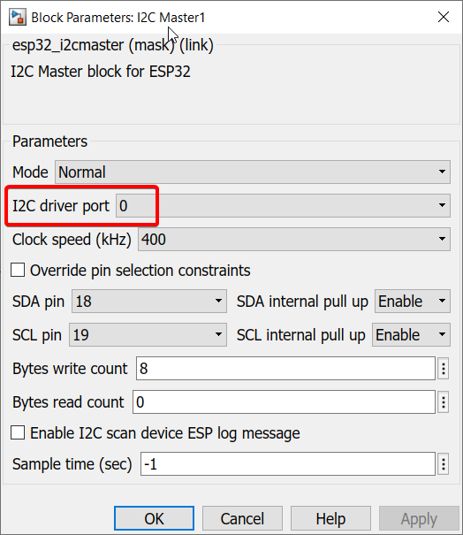
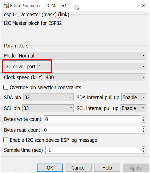
However, you still need to add a simple algorithm that will determine that there is a car in close range to complete the I2C modules. For instance, set it up in such a way that if anything is detected by the sensor within a range of 100mm, only then will it consider turning ON. Anything above 100mm will keep the sensor OFF.
This sensor can detect values up to 2000mm so it will display how far something is if it falls in that range, which is why you need to add a filter accordingly.
We suggest that you use 'Switch' blocks for this purpose and configure them accordingly.
Tips and tricks to build HIL model:
1.Import a 'Waijung 2 Target Setup' block > Double click on block > Build options > External mode simulation.
2.Replace manual switches with Waijung 2 'Digital Input' block. Double click on block > Pull mode > Pull-down
3.Replace 'Scope' with Waijung 2 'Digital Output' block.
4.Replace 'Signal Builders' with the two I2C modules
5.Before running HIL on this model, please make sure you have installed Waijung 2 latest version as we have improved and optimized External Mode communication in this latest release for more complicated models such as this one.
6.Repeat the same procedure shown for HIL simulation in Projects 1 & 2 to see your hardware and software work together in action.
Final result (click to view video):
1.As is evident, the dip switch allocated for Sensor mode is turned on in the first few seconds of the video. Then, once Sensor 2 detects anything in a close range of within 100mm, the traffic light turns green. You can also see that detection within a range of 100mm gives an output of 1 from 'I2C sensor 2' module which is then inputted to the Control Algorithm Stateflow Chart.
2.As soon as the thumb is removed, there is nothing in a range of 100mm, hence the 'I2C sensor 2' module outputs a 0 and the traffic light goes to yellow and red
3.The same procedure in 1 and 2 is then repeated with Sensor 1
4.Then, both thumbs are used to cause both sensors to detect at the same time. As specified earlier in the Note section under Project Description, if both sensors detect something simultaneously, the system will run in automatic timer mode. Thus, the system shifts to the Automatic subchart. You can also see that both I2C sensor modules output a 1.
5.At T = 1:10, as one of the thumbs is moved beyond the 100mm point, I2C sensor 1 outputs a 0 and the system moves back to Sensor subchart as an object is only detected on one side.
6.Then, starting at T = 1:22, both thumbs are once again within a range of 100mm from the sensors and Automatic subchart is activated. The system runs in automatic timer mode until T = 1:56
7.Then, the Manual subchart is tested. The dip switch allocated for Manual mode is turned on and this causes the traffic light to remain green until dip switch is turned off manually at T = 2:15
8.Then, the system goes back to Sensor mode as the dip switch allocated for Sensor mode is turned on once again. Hand is placed in front of both sensors at T = 2:44, however it is not within the range of 100mm. Then, as hand is moved closer, both sensors detect the hand within 100mm and the Automatic mode is activated again.


