Project description
1.In Project 3, you learnt how to design a control system to control traffic in the event of road repairing. This kind of system continues to run automatically according to the specified time. However, it will cause inconvenience when a vehicle is waiting for the light to turn green on one side, while the other side is green without the presence of any vehicles.
2.To improve the system, incorporate a switch into the control system to allow officers to manually turn on/off both sets of traffic lights whenever needed.
3.Use 2 digital input switches to control 4 working modes as follows:
a.00 - Mode 0: Red light ON for both set 1 and set 2.
b.10 - Mode 1: Green light ON for set 1 (until turned off), Red light ON for set 2. Allow a time delay of 10 seconds before green light changes to yellow after status of the switch is changed.
c.01 - Mode 2: Green light ON for set 2 (until turned off), Red light ON for set 1. Allow a time delay of 10 seconds before green light changes to yellow after status of the switch is changed.
d.11 - Mode 3: Runs automatically according to the specified time as developed in Project 3
Note for safety:
1.Once one side turns red, you'll need to make sure there's sufficient time for the cars to pass and get to the other side before the other side turns green. Assume that this time delay is 10 seconds.
2.When changing the status of the switch, the mode running must be completed first. This will allow time for the officers to plan what mode they want to be running next.
Learning objectives
In this tutorial you will learn:
1.What is a DIP switch
2.How to interface with a DIP switch
3.How to use Stateflow to model more complex control systems
4.Applications of traffic light control
Required hardware
No. |
Item |
Picture |
Quantity |
1 |
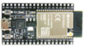
ESP32 with USB cable |
|
1 |
2 |
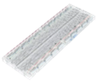
Protoboard (830 points) |
|
1 |
3 |
Jumper Wire Male-Male |
|
12 |
4 |
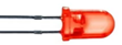
Red 5mm LED |
|
2 |
5 |
Amber 5mm LED |
|
2 |
6 |
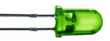
Green 5mm LED |
|
2 |
7 |
Resistor 220 Ohms |
|
8 |
8 |
USB Wi-Fi dongle (only necessary if you need to use External Mode in WiFi AP configuration) |
|
1 |
9 |
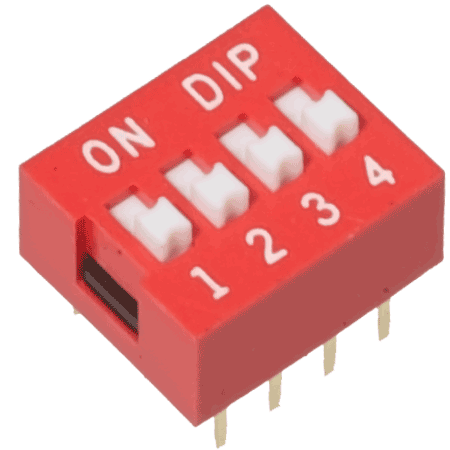
Dip switch (4 pins) |
|
1 |


Hands-on
Software in the Loop (SIL) simulation
Tips and tricks to build SIL model:
1.Import two 'Manual Switch' from Library Browser to represent the 4 working modes as stated in Item 3 of the project description. Use constant blocks of '0' and '1' for the two modes of each switch.
2.Using a Stateflow Chart, build the 4 working modes first. For example:
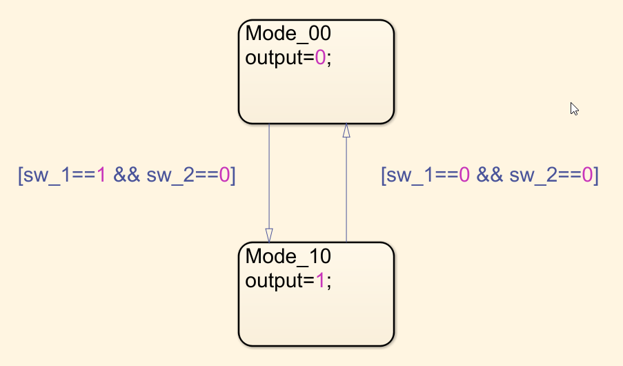
3.Using the same format as shown above, build the rest of the modes and the transitions between them.
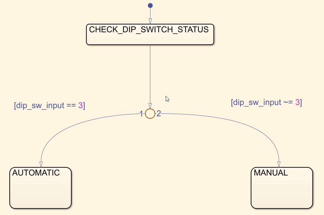
4.Once the four working modes are built, realize that 'Manual' control is for 'Outputs' 0, 1, and 2, while Output 3 is for 'Automatic' control (already designed in Project 3). Keeping this in mind, you can divide your control system into two parts as shown below:
5.Within the 'Manual' sub-chart, 'Mode 0' could be set as the default event, which helps to transition to Mode 1 and Mode 2 whenever the status of the switch is changed. For example:
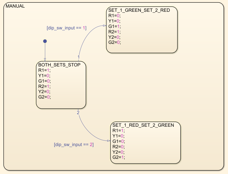
6.Build the rest of the 'Manual' sub-chart to complete the transition between Modes 0, 1 and 2.
7.Set conditions to transition between 'Manual' and 'Automatic' sub-charts.
Hardware in the Loop (HIL) simulation
Hardware setup
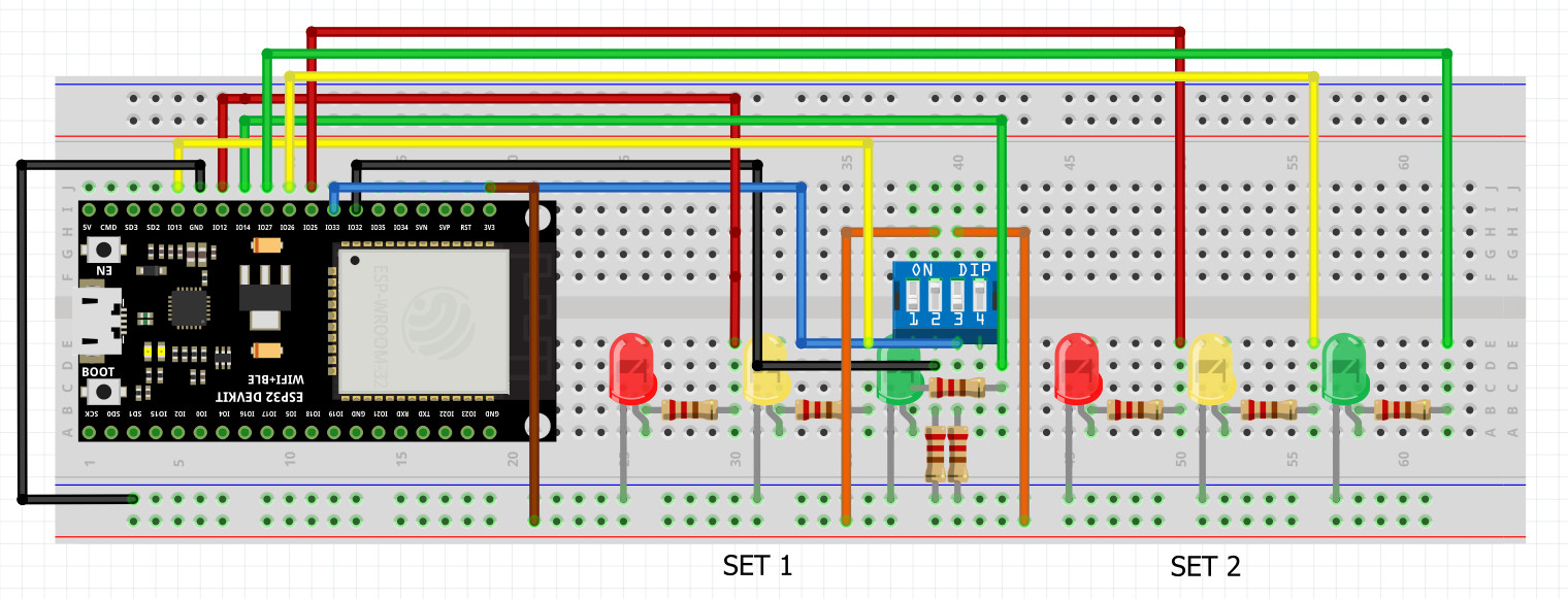
Tips and tricks to build HIL model:
1.Import a 'Waijung 2 Target Setup' block > Double click on block > Build options > External mode simulation.
2.Replace manual switches with Waijung 2 'Digital Input' block. Double click on block > Pull mode > Pull-down
3.Replace 'Scope' with Waijung 2 'Digital Output' block.
4.Repeat the same procedure shown for HIL simulation in Projects 1 & 2 to see your hardware and software work together in action.
Final result (click to view video):
As is evident, GPIO 32 and GPIO 33 represent the dip switch binary input, through which the four modes (as stated in item 3 of project description) are controlled.