Project description
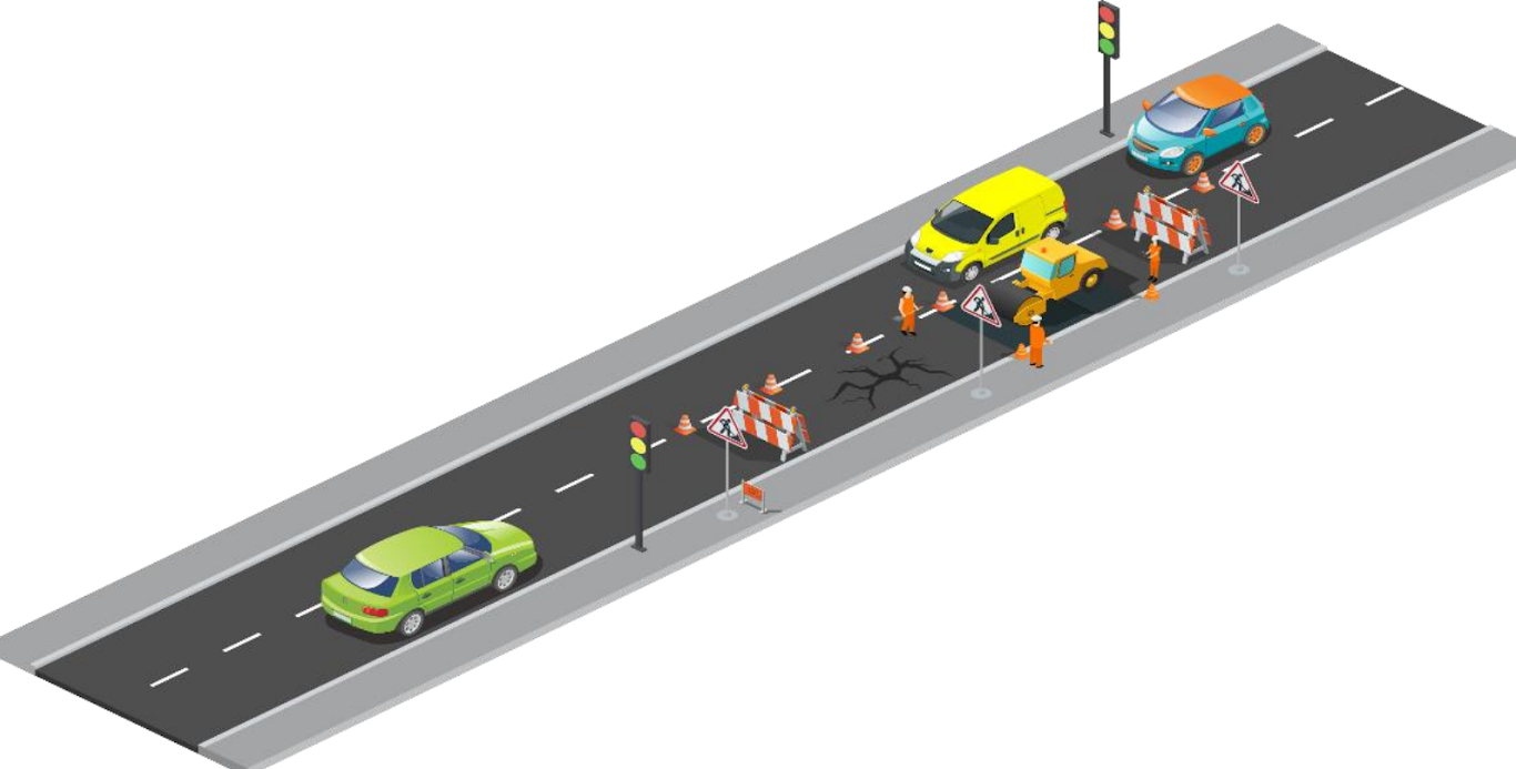
In this project you will design a control system to control traffic in the event of road repairing, as shown below.
1.Usually, there are 2 lanes of road where cars can freely go past each other in opposite directions. However, if one lane must be closed for road repairing, all cars can only use one lane.
2.Build on your control system developed in Project 2 to control 2 sets of traffic lights to allow all cars to use one lane without problems.
3.Once one side turns red, you'll need to make sure there's sufficient time for the cars to pass and get to the other side before the other side turns green. Assume that this time delay is 10 seconds.
Learning objectives
In this tutorial you will learn:
1.How to use Stateflow to model a more complex event-driven system
2.Applications of traffic light control
Required hardware
No. |
Item |
Picture |
Quantity |
1 |
ESP32 with USB cable |
|
1 |
2 |
Protoboard (830 points) |
|
1 |
3 |
Jumper Wire Male-Male |
|
7 |
4 |
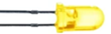
Red 5mm LED |
|
2 |
5 |
Amber 5mm LED |
|
2 |
6 |
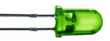
Green 5mm LED |
|
2 |
7 |
Resistor 220 Ohms |
|
6 |
8 |
USB Wi-Fi dongle (only necessary if you need to use External Mode in WiFi AP configuration) |
|
1 |


Hands-on
Software in the Loop (SIL) simulation
As all the steps have been shown in both Projects 1 & 2, it is unnecessary to repeat showing the same steps. Therefore, we recommend you to use your knowledge from Projects 1 & 2, to complete this project.
Tips and tricks to build SIL model:
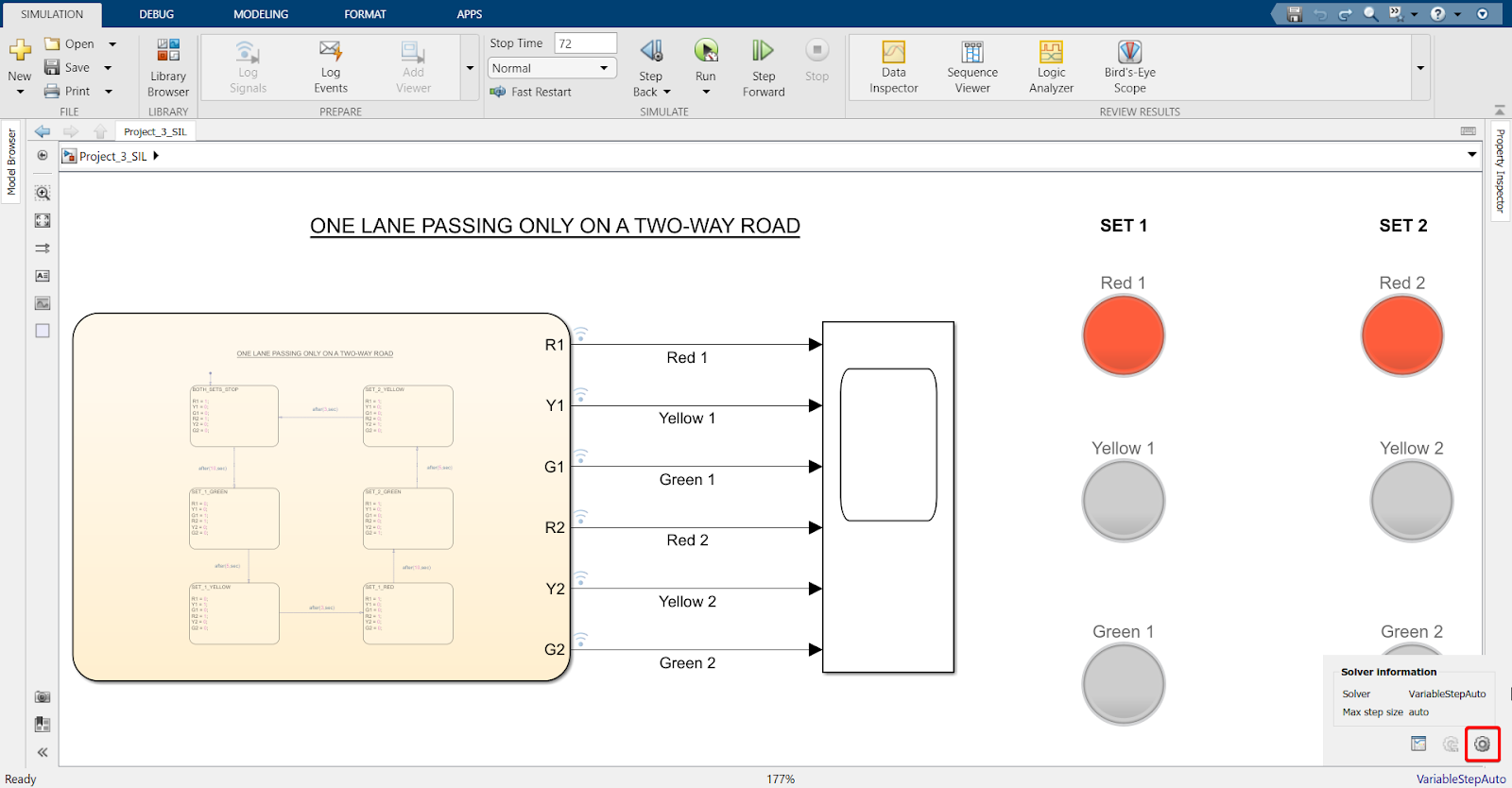
1.Implement 2 sets of traffic lights (6 'Lamp' elements)
2.Connect 6 signals to scope
3.Select appropriate transition time between all states. Make sure to have the time delay of 10 seconds after one side has turned red before the other side turns green.
4.Check your scope after the simulation has completed to confirm its working. The signals should be alternating between '1' and '0' according to the timing they have been given through the Stateflow chart.
Note
If the scope is showing some kind of delay (for instance - according to the timing you have given in your Stateflow chart, Yellow light must be turning on at 15 second and off at 18 second, but your Scope is showing 15.5 and 20, respectively), then you need to change the type of solver and the sample time in your model.
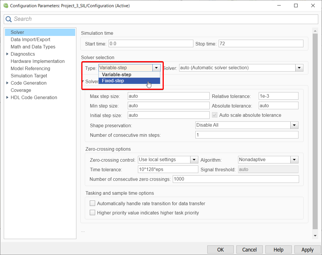
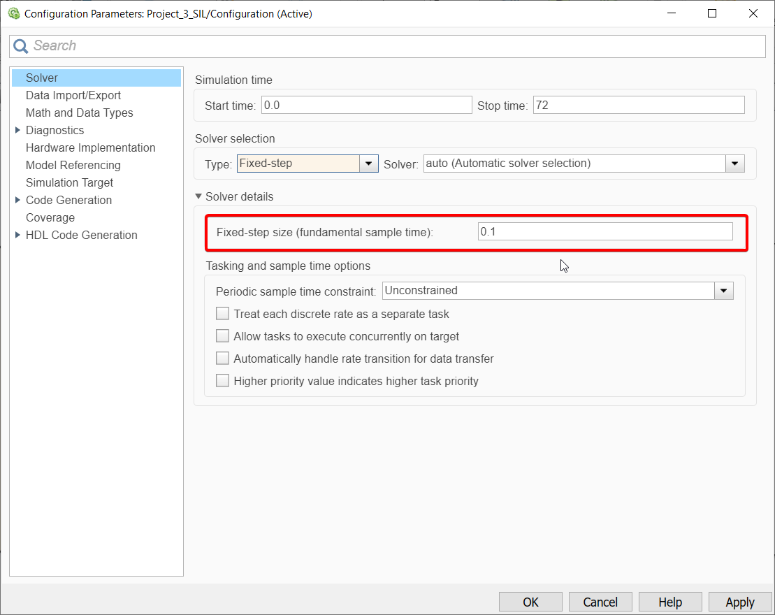
Changing solver type and sample time
1. Click on bottom right corner of your model screen
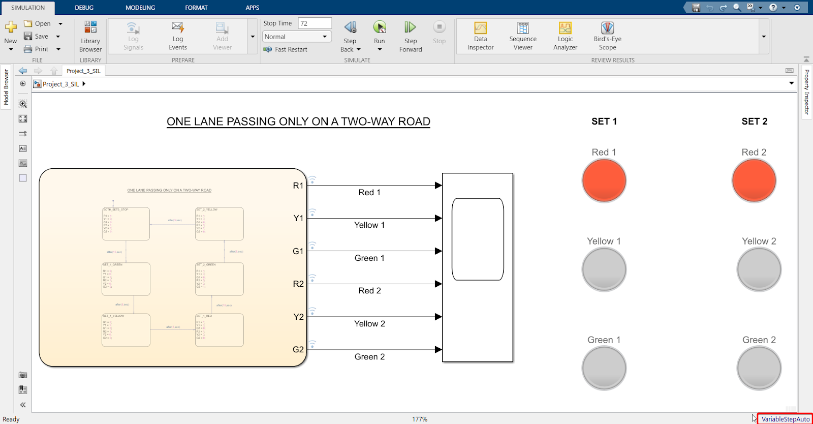
2. Click on the Settings icon
3. Change solver type to Fixed-Step
4. Change Fixed-step size to 0.1
Explanation
A sample time of 0.1 means that a data point will be collected and every 0.1 second. With a larger sample time certain data points are sometimes missed, which affects the accuracy of the result. Generally, a small sample time of 0.1 second would allow every data point to be collected, hence resulting in an accurate result. A Fixed-step solver means this sample time of 0.1 remains fixed throughout the simulation.
Once SIL is working correctly, please try to see if your designed model is working on hardware too.
Stand-Alone (SA)
Hardware setup
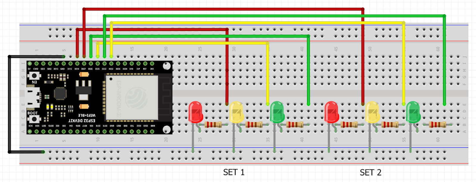
Tips and tricks to build SA model:
1.Slight modification needed from the SA model used for Project 2: 6 pins must be connected to the 'Digital Output' block instead of just 3 pins to account for the extra set of LED lights.
2.Then, repeat the same procedure shown in Projects 1 & 2 to convert the SA model into C code and flash onto ESP32 Micro-controller to see the hardware in action.
Final result (click to view video):