Project description
In this project you will design a basic traffic light control system according to the sequence as follows:
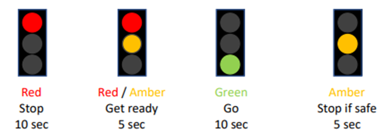
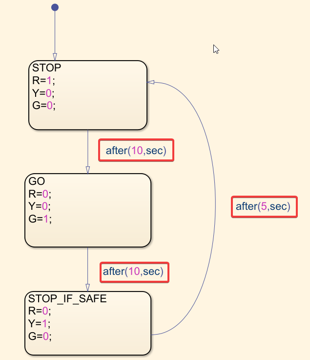
1.Stop state (Red): ON for 10 sec
2.Go state (Green): ON for 10 sec
3.Stop if safe state (Yellow): ON for 5 seconds
4.Return to stop state (Red)

Learning objectives
In this tutorial you will learn:
1.How to use Stateflow to model an event-driven system
2.Using Stateflow and Simulink together
3.Display multiple signals in Scope
4.More about MBD workflow (SIL, HIL, SA)
Required hardware
No. |
Item |
Picture |
Quantity |
1 |
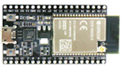
ESP32 with USB cable |
|
1 |
2 |
Protoboard (830 points) |
|
1 |
3 |
Jumper Wire Male-Male |
|
4 |
4 |
Red 5mm LED |
|
1 |
5 |
Amber 5mm LED |
|
1 |
6 |
Green 5mm LED |
|
1 |
7 |
Resistor 220 Ohms |
|
3 |
8 |
USB Wi-Fi dongle (only necessary if you need to use External Mode [see HIL simulation section below] in WiFi AP configuration) |
|
1 |


Hands-on
Software in the Loop (SIL) simulation
For this kind of project description, we must use 'Stateflow', since it is a very efficient tool to simulate the transition from one state to the next.
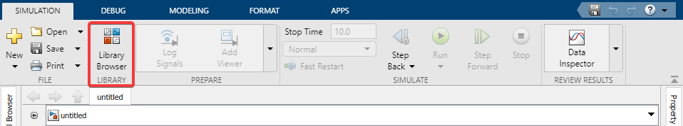
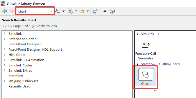
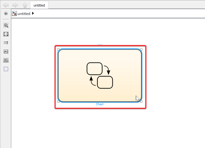
1. Import ‘Chart’
2. Double-click on the chart
3. Since we need 3 states, we can use 3 separate boxes.
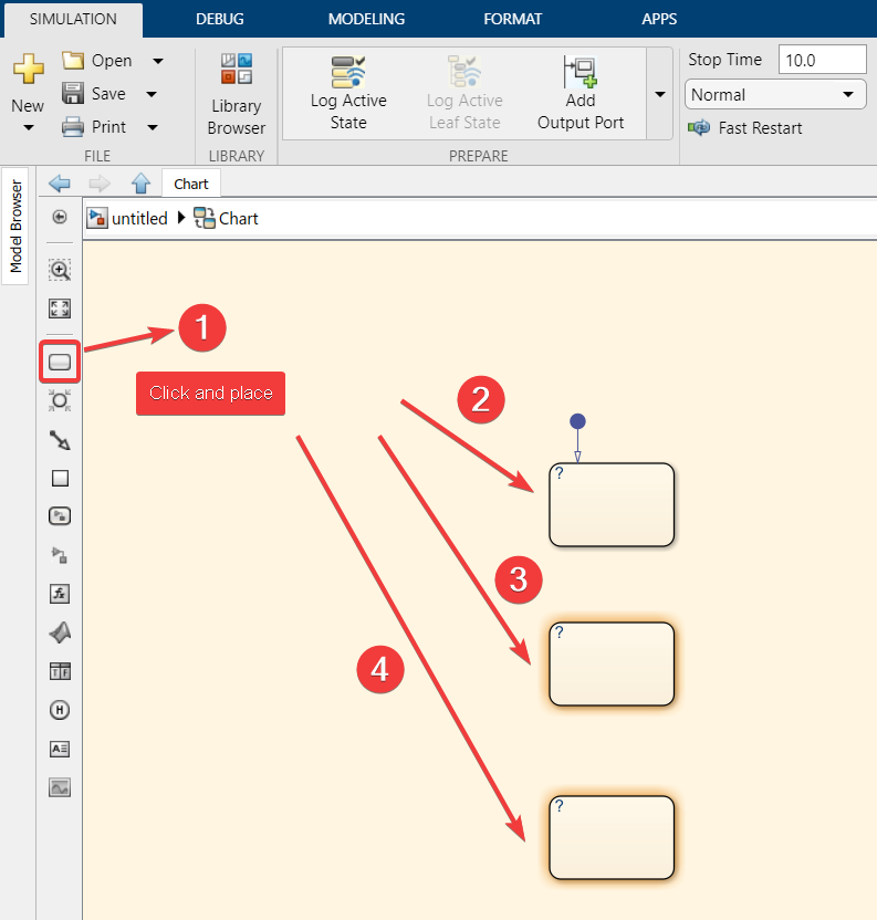
4. Connect the 3 states
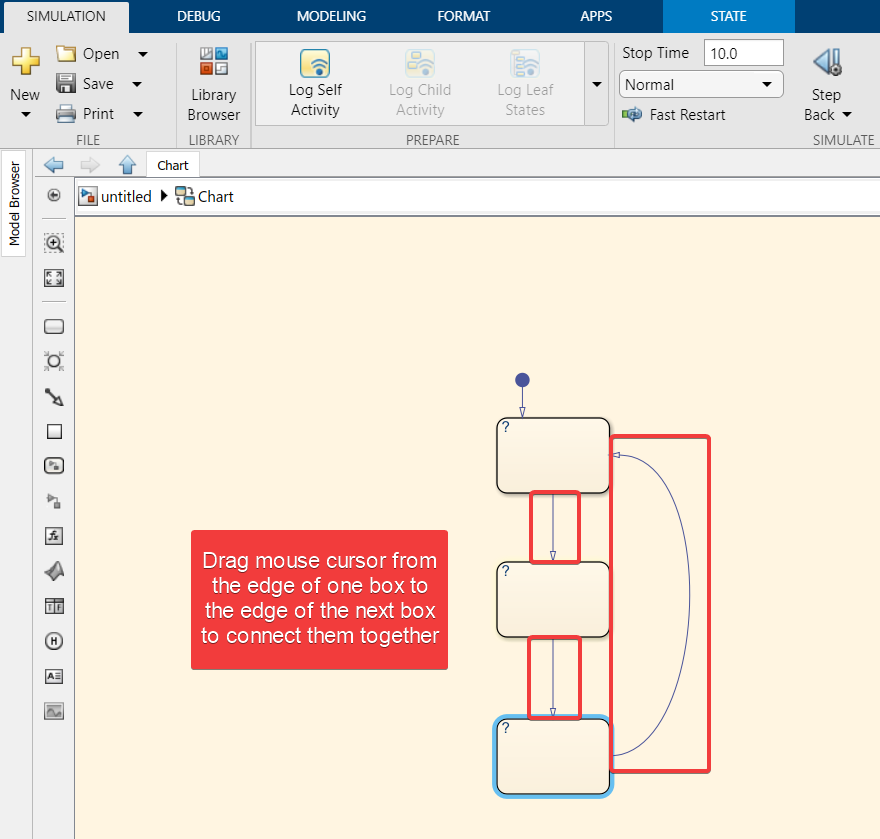
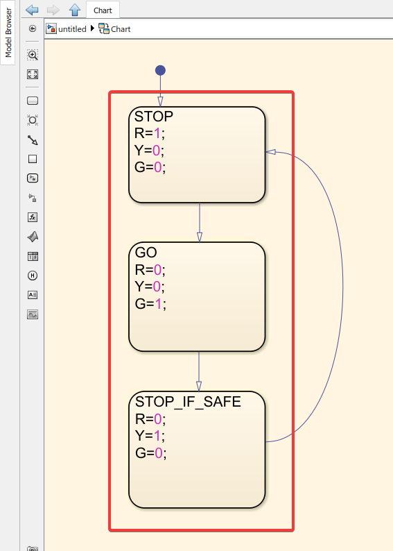
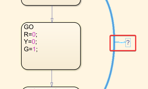
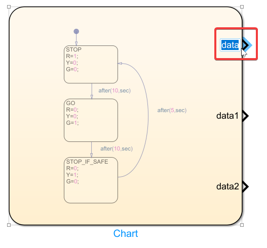
5. Label the states (STOP for red light, GO for green light, STOP_IF_SAFE for amber light). Use R,Y,G for the three colours. Use 1 and 0 as values for ON/OFF, respectively.
6. When you click on the indicated line, a “?” square will appear. Click on it and enter the desired transition time between the two respective states
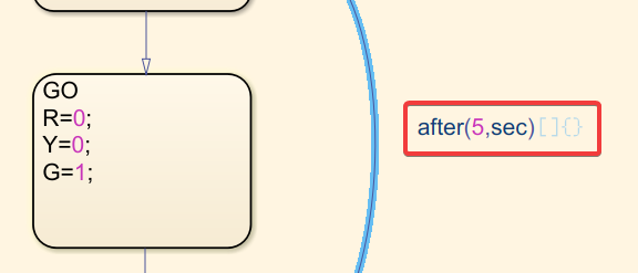
7. Enter the transition time for the other states
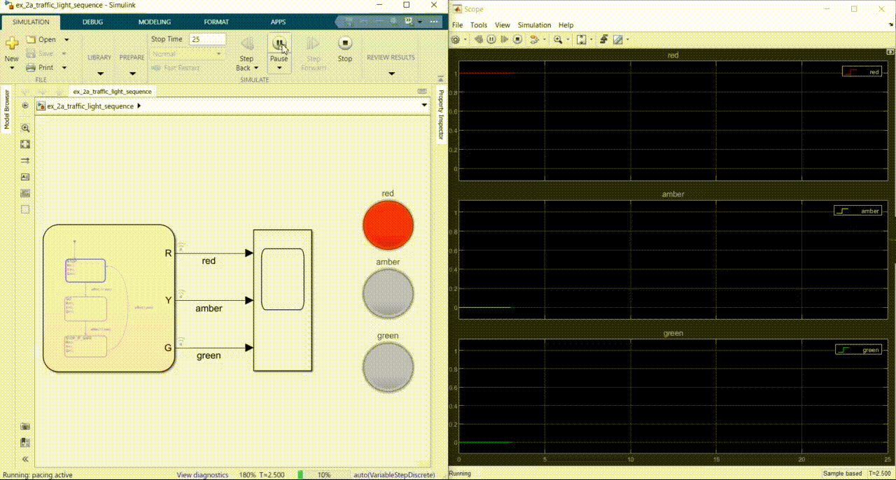
8. Connect the 3 states to a scope
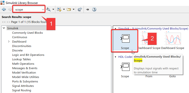
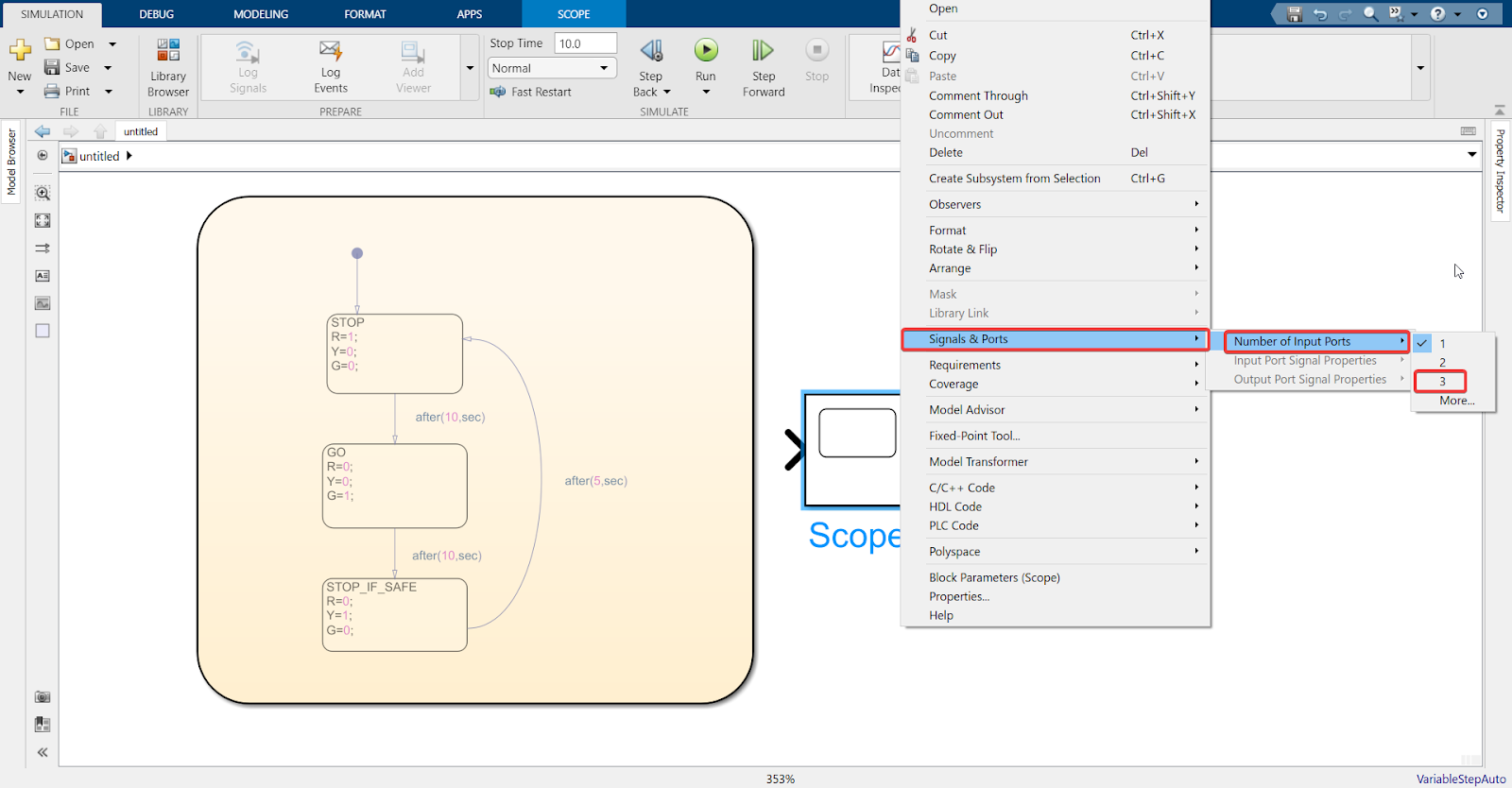
9. Right-click on Scope > Signals & Ports > Number of Input Ports > 3
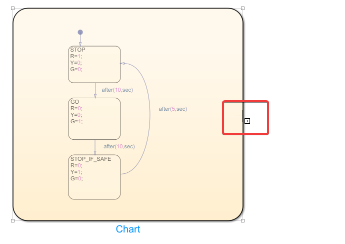
10. Click on the edge of the chart, then click on the ‘+’ sign that appears
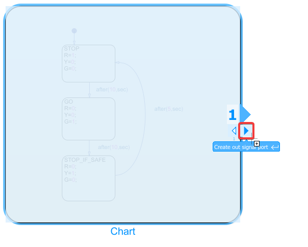
11. The following will appear after you click on the ‘+’ sign . Create an out signal port.
12. Repeat steps 10 and 11 to create two more output ports
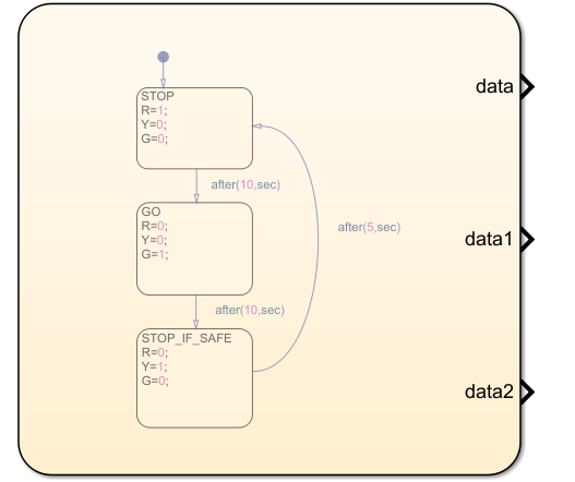
13. Rename to R, Y, G
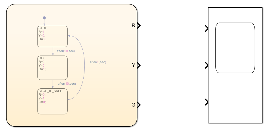
14. Connect the three states to the scope
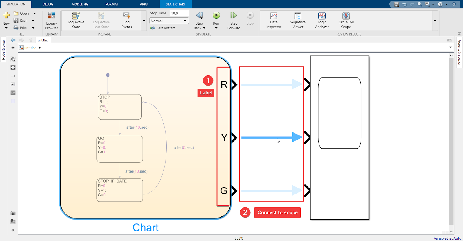
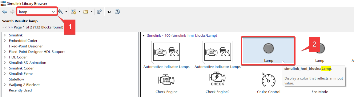
15. Import ‘Lamp’ and connect it to the 3 states
16. Double-click on the Lamp and follow the steps below:
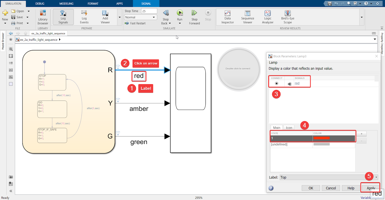
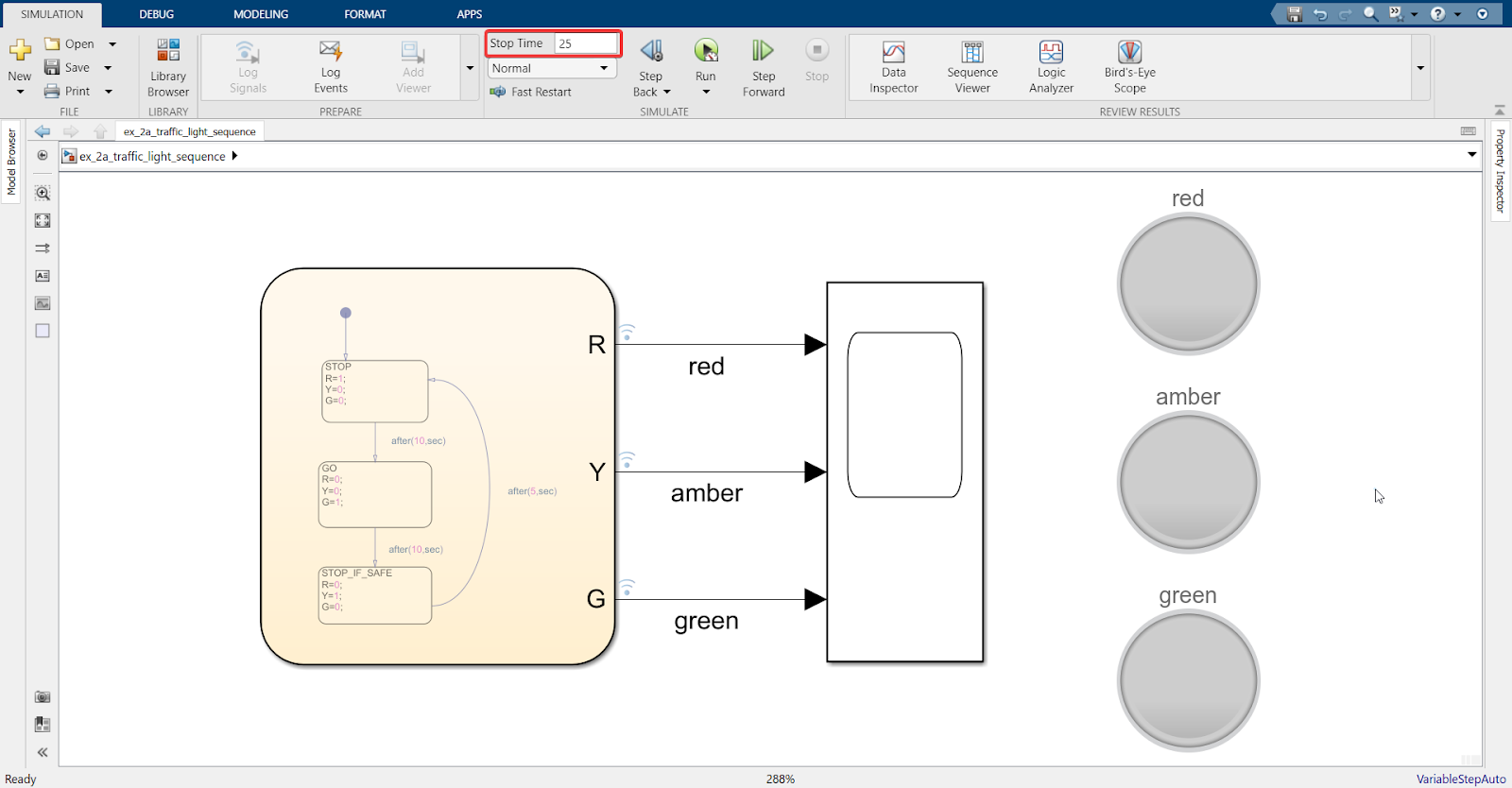
17. One cycle runs for 25 seconds (Red: 10, Green: 10, Yellow: 5), so set the ‘Stop Time’ accordingly.
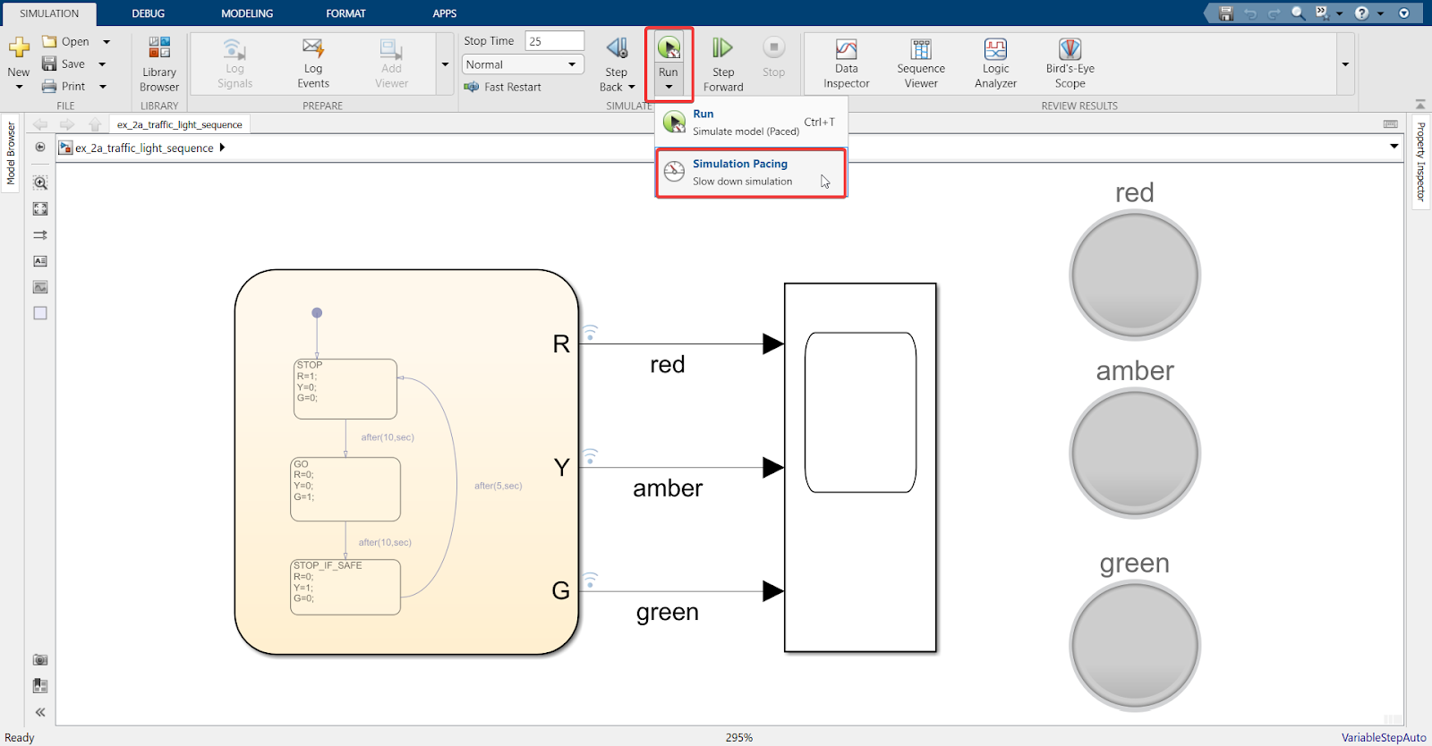
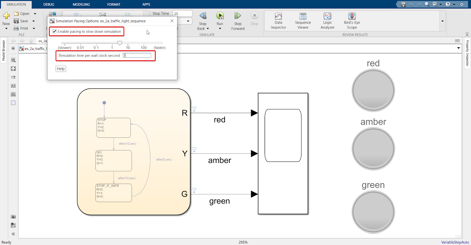
18. Activate a paced simulation under Run > Simulation Pacing > Enable Pacing, in order to see real-time results.
Explanation
Keeping “Simulation time per wall clock second” to 1 would show real-time results, which means that 1 cycle will run for 25 seconds. To check whether the model is working well, we do not need to wait 25 seconds for every cycle to complete. Increasing “Simulation time per wall clock second” to a larger value such as 3 will reduce simulation time by 3x (25/3 = 8.33 sec) while still showing the entire 25 second cycle.
19. Save and run the model
20. Result
Since SIL is working correctly, we can continue with HIL.
Hardware in Loop (HIL) simulation
Hardware setup
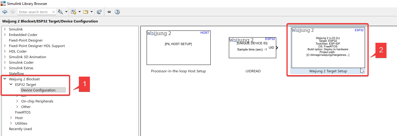
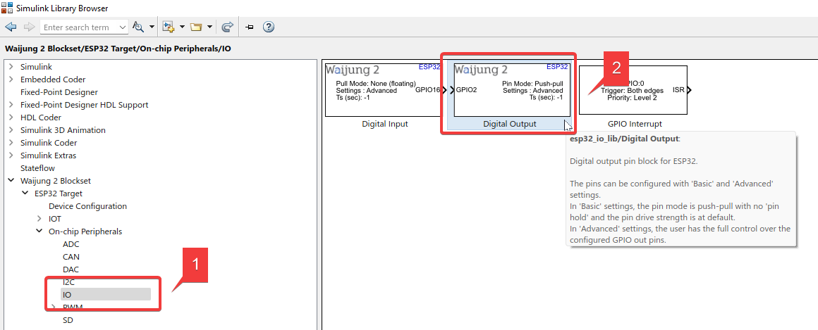
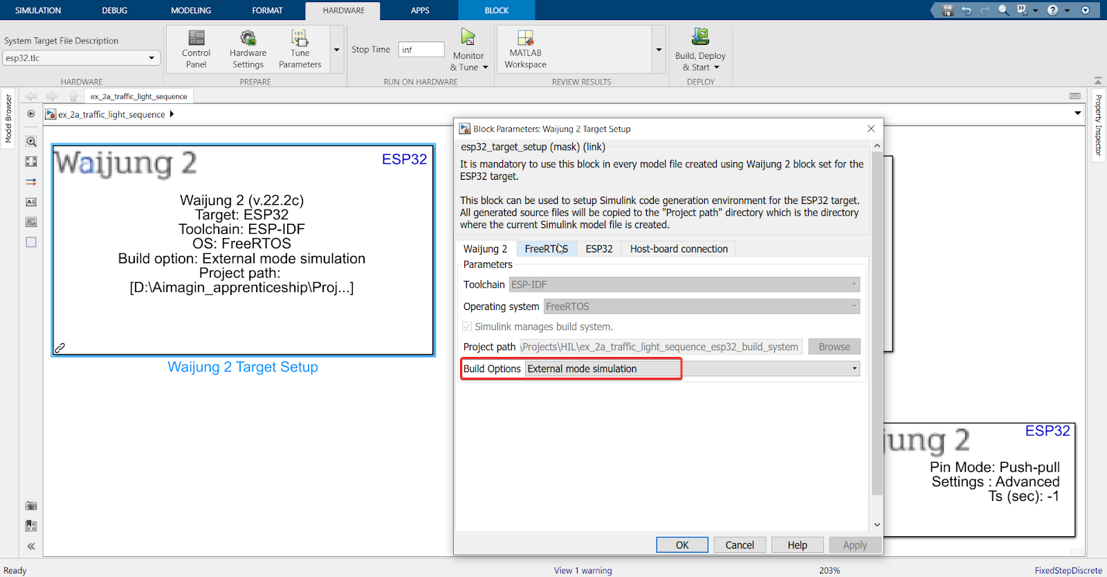
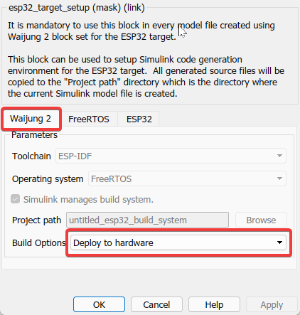
1. Import ‘Waijung 2 Target Setup’ and ‘Digital Output’ blocks
2. Select ‘External mode simulation’
Note
For more information on External Mode, please refer back to the HIL section of Project 1. We have explained it in detail there.
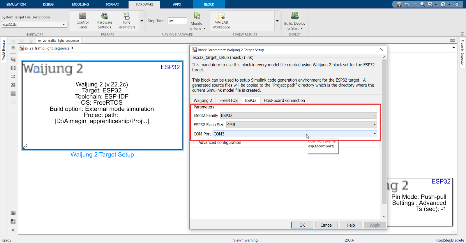
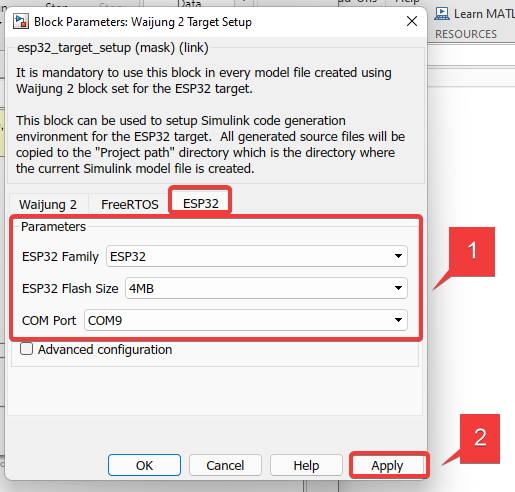
3. Connect your ESP32 board to your computer and the following will be detected automatically
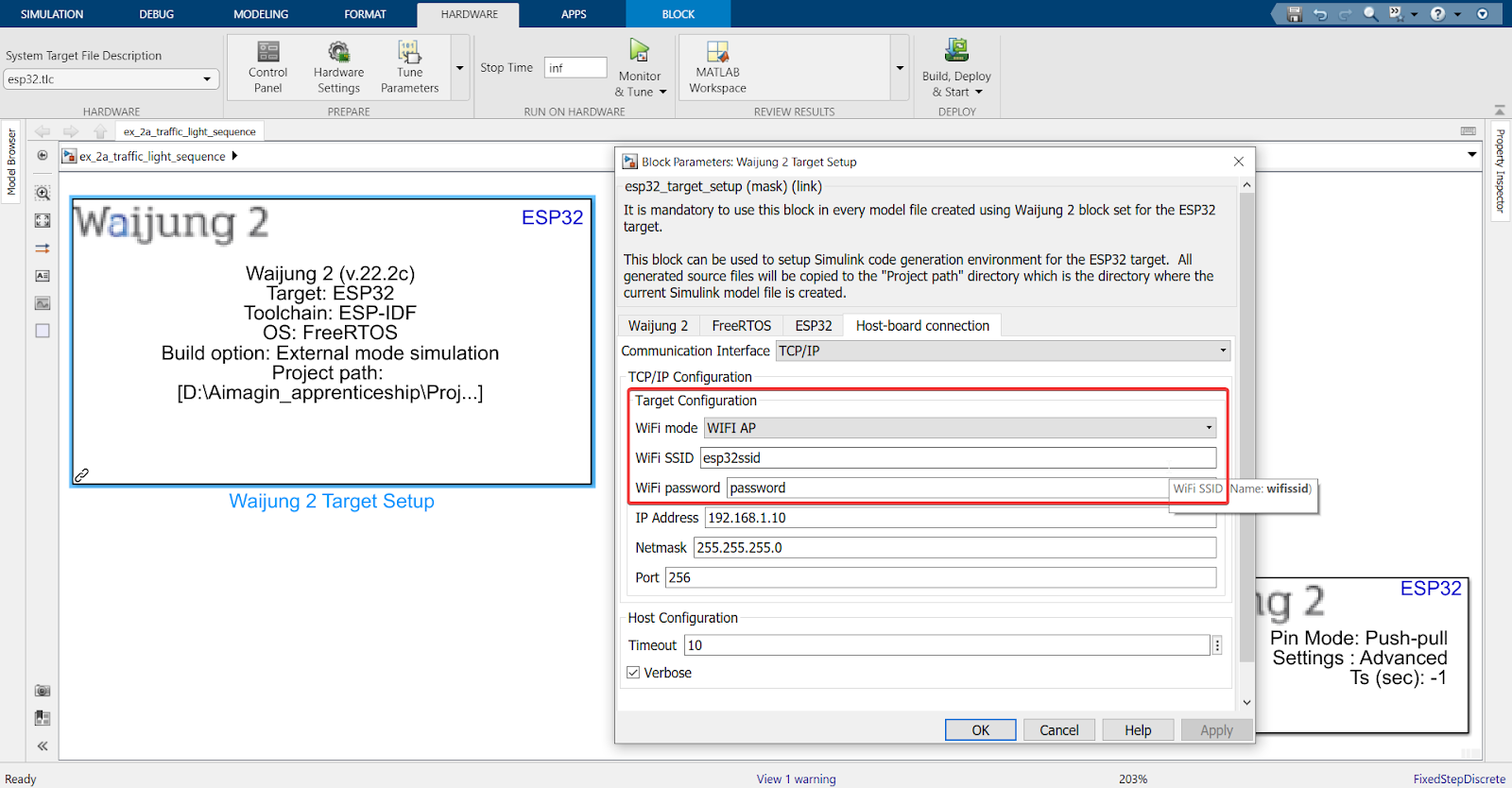
4. Set WiFi and password to make your ESP32 an access point
OR
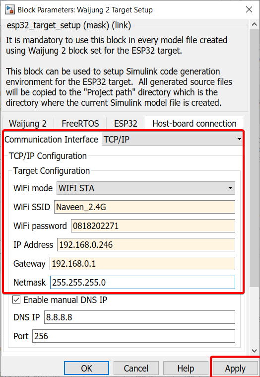
In the Host-board connection tab, you can set up the WiFi Station Mode by using the SSID and password that your computer uses to connect to the internet.
Note: All ESP32 boards only support 2.4GHz bandwidth (except the recently released ESP32-C5 which also supports 5GHz), so make sure the WiFi you connect your ESP32 board to in WiFi STA mode lies in the 2.4GHz frequency range
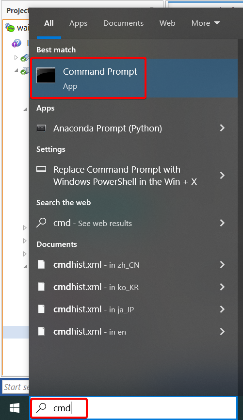
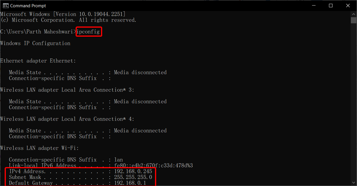
For the IP address, Gateway, and Subnet mask, please search for "command prompt" or "cmd" and type "ipconfig" to find the configurations and input them into the target setup.
Note: For the IP address, choose any number between 0 to 255 for the last 3 digits, except the IPv4 address listed in command prompt (since that is the IP address assigned to your computer).
OR
In the Host-board connection tab, select Serial as the communication interface. Check the datasheet of the board to find the tx and rx pins related to the UART module. Usually UART0 is connected to programming Serial port. For instance, this example is based on ESP32-WROOM board:
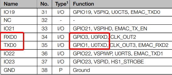
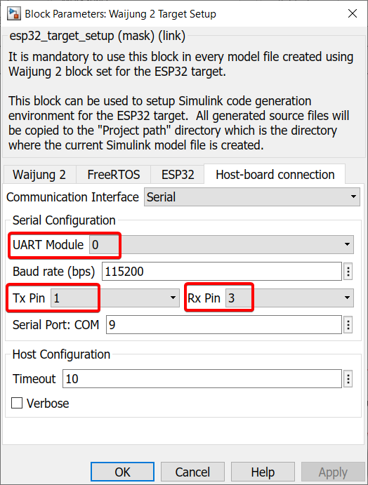
The above right image is from the ESP32-WROOM datasheet where UART0 module's transmitter (Tx) and receiver (Rx) are represented by GPIO 1 and GPIO 3, respectively. These are the configurations needed for the Waijung 2 target setup block in the above left image. Make sure you check your board's datasheet to find the correct Tx and Rx pins related to the UART module.
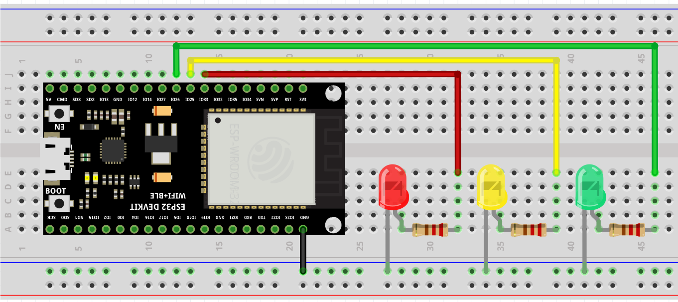
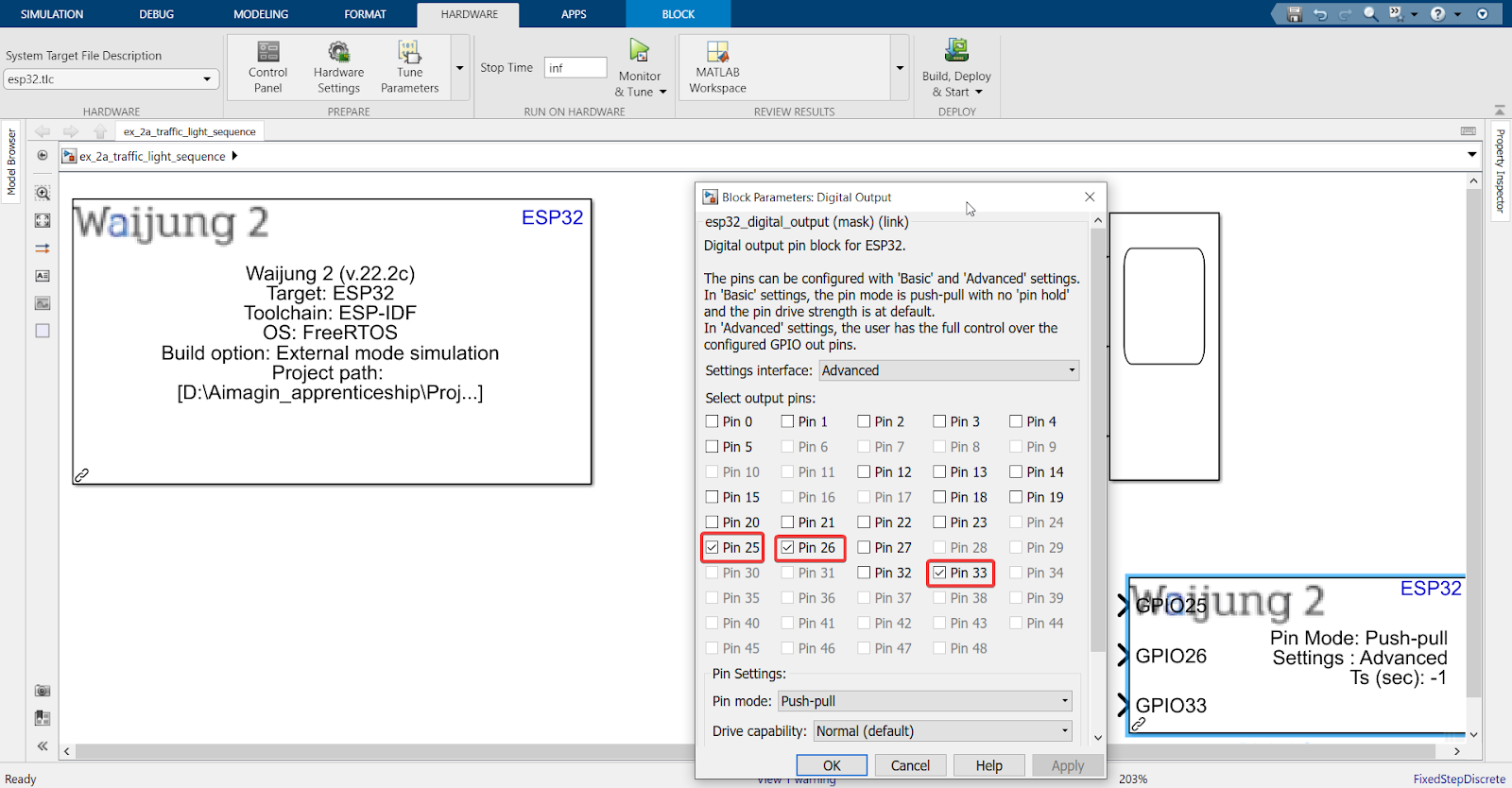
5. Select 3 pins for the respective 3 LEDs
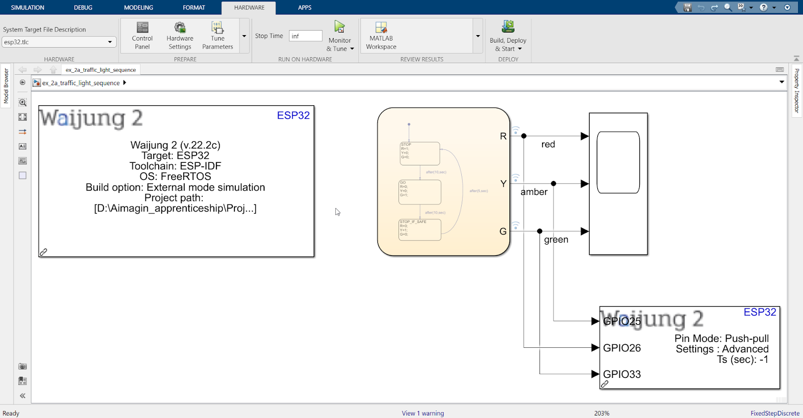
6. Connect according to the following
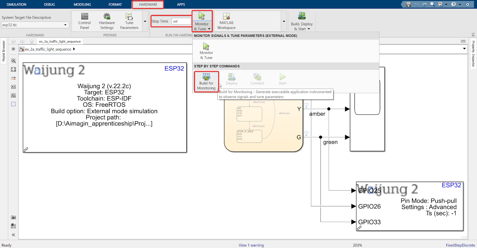
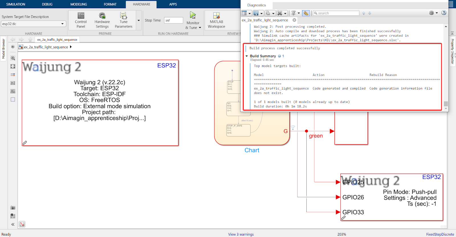
7. Go to ‘Hardware’ Tab > Monitor & Tune > Build for Monitoring. Also, set ‘Stop Time’ to ‘inf’
Note: Step 8 is only for users who have chosen WiFi AP as the configuration mode. For WiFi STA and Serial, please skip to Step 9.
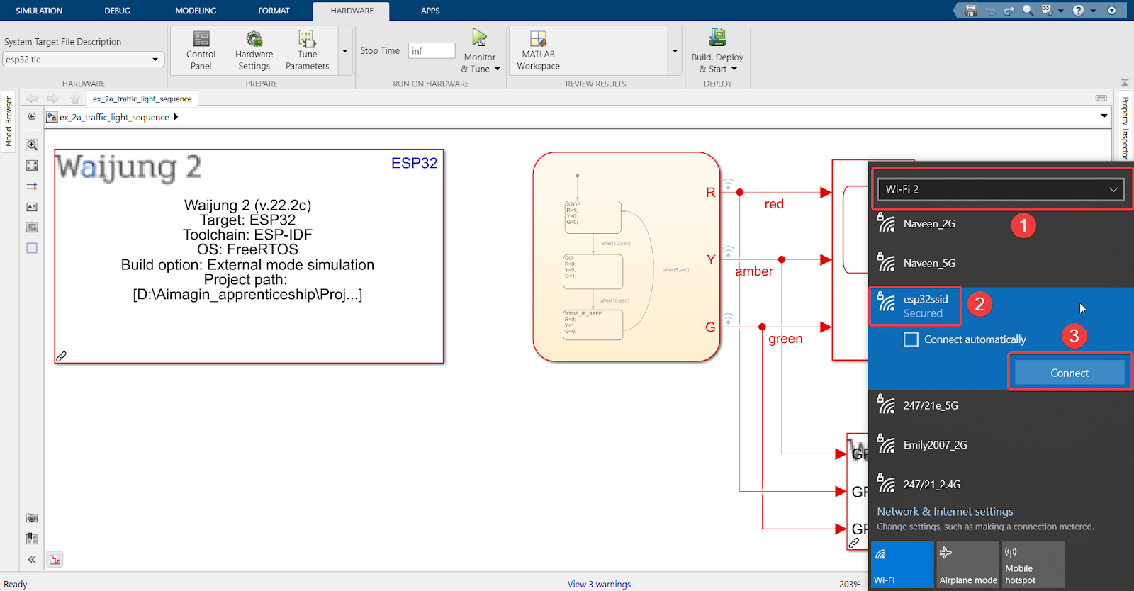
8. Once build is complete, connect the USB Wi-Fi dongle to your computer > Go to Wi-Fi 2 through your computer > connect to the access point created by the ESP32 using the SSID and password that was set in the Waijung 2 Target Setup block.
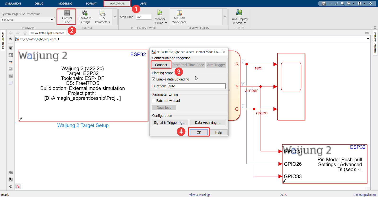
9. Finally, go to the ‘Hardware’ tab > Control Panel > Connect > OK
10. Save the file and run the model
11. Final result (click to view video):
Stand-Alone (SA)
Let us now test the SA operation
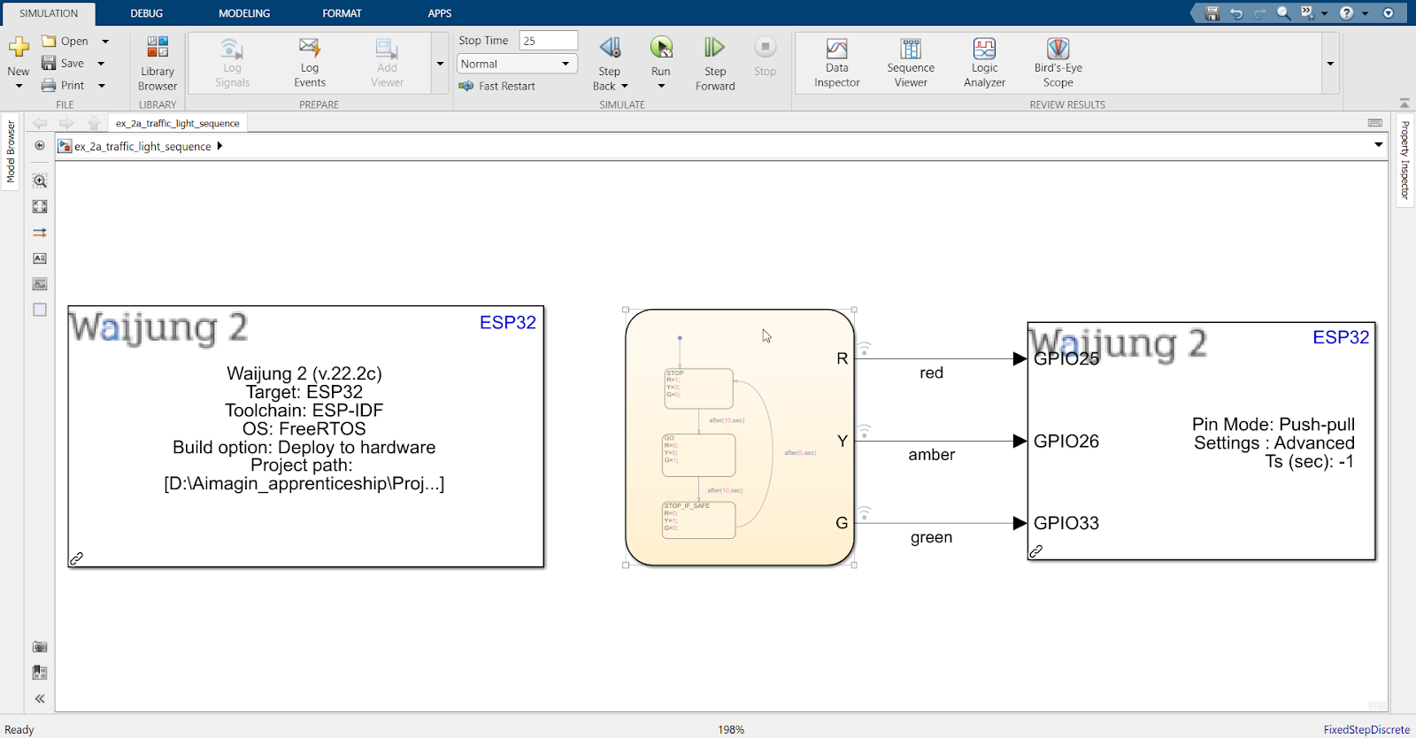
1. In the ‘Waijung Target Setup’ block, set up according to the following:
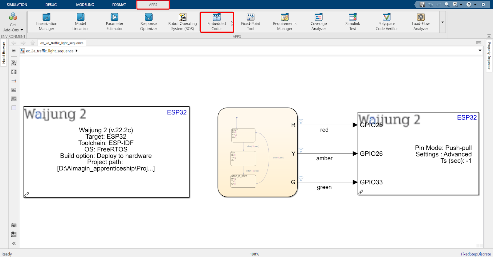
2. Go under ‘APPS’ and click ‘Embedded Coder’
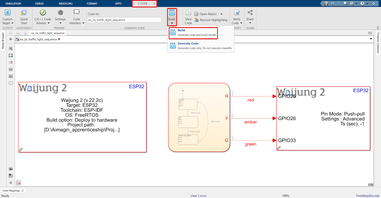
3. Click ‘Build’
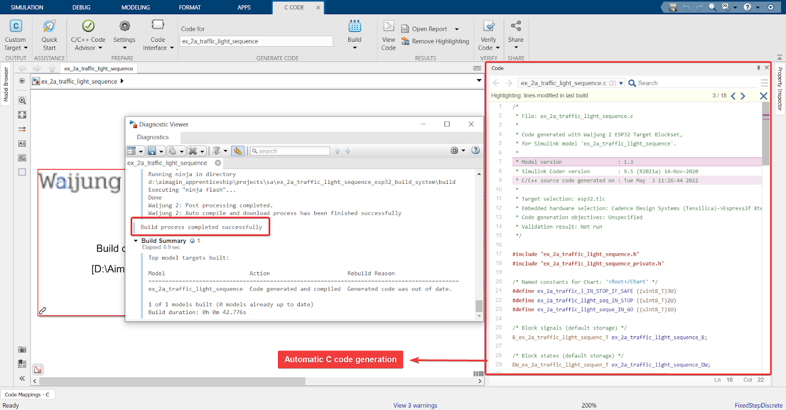
4. Result (click to view video)
This is the end of this tutorial. To apply your learning, you can test yourself with an exercise.
Exercise
Add a “Get ready to go” state into the existing model. Conduct SIL, HIL, and SA.