Project description
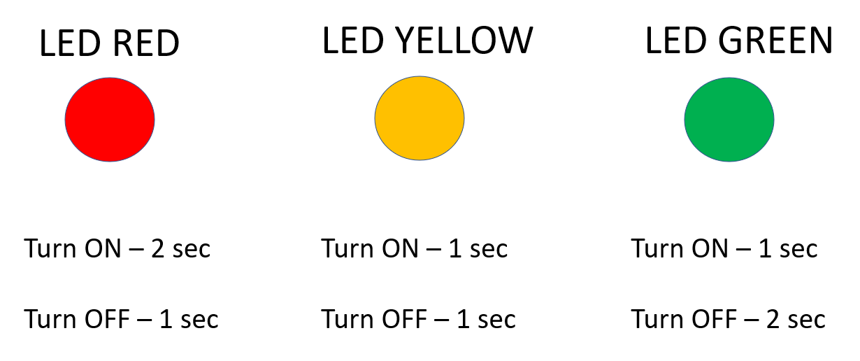
In this project you will make a road safety warning light that turns ON for 1 second and then turns OFF for 1 second continuously, as shown below.

Learning objectives
In this tutorial you will learn:
1.How to create a simple Simulink model
2.Model-Based Design (MBD) workflow
a.How to use ESP32 and its pins
b.How to simulate the model (Software in the Loop - SIL simulation)
c.How to deploy the simulation model to hardware (ESP32)
d.How to run simulation with real hardware (Hardware in the Loop - HIL simulation)
e.How to deploy as a Stand Alone (SA) device
Required hardware
No. |
Item |
Picture |
Quantity |
1 |
ESP32 with USB cable |
|
1 |
2 |
Protoboard (830 points) |
|
1 |
3 |
Jumper Wire Male-Male |
|
2 |
4 |
Amber 5mm LED |
|
1 |
5 |
Resistor 220 Ohms |
|
1 |
6 |
USB Wi-Fi dongle (only necessary if you need to use External Mode [see HIL simulation section below] in WiFi AP configuration) |
|
1 |


Hands-on
Software in the Loop (SIL) simulation
Software-in-the-loop (SIL) is a method to test your algorithm in a pure computer simulation environment without actual hardware (learn more about SIL).
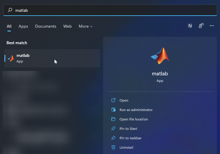
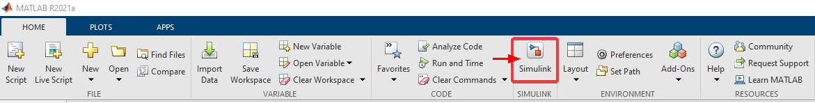
1.Open MATLAB
2.Click on Simulink
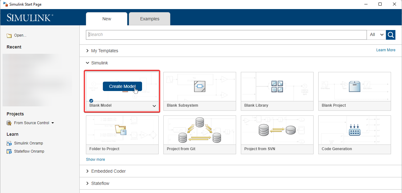
3.Click on Blank Model to create a model
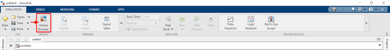
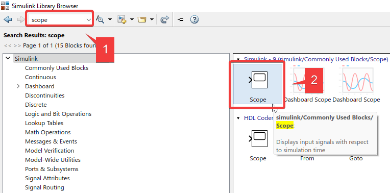
4.Click on Library Browser to find various blocks to build your model
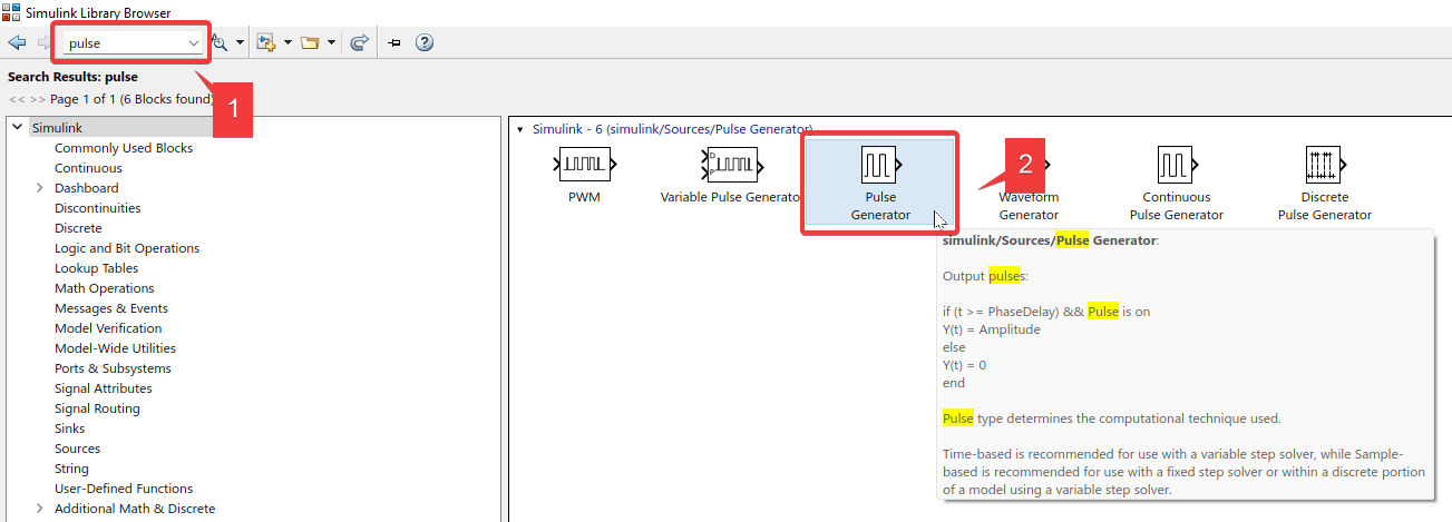
5.To model the situation in this project, we can use the ‘Pulse Generator’ block in Simulink. As the name suggests, this block can help generate binary pulses of different frequencies.
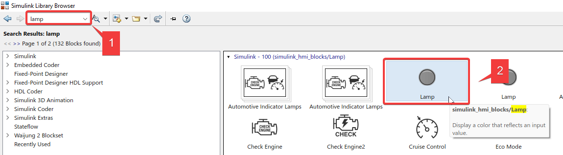
6.Add a scope (to display results graphically) and a lamp to the model (to display the blinking)
7.Double click on Pulse Generator to configure its parameters
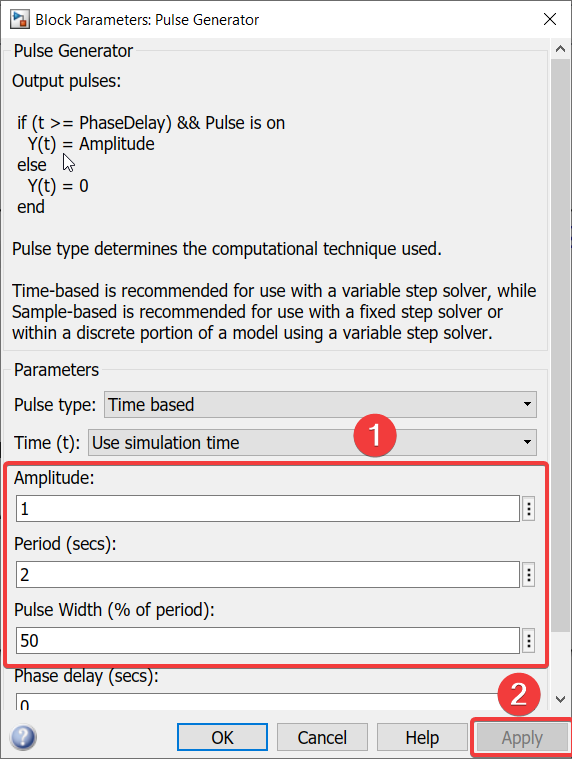
To set the conditions for this block, we need to refer back to the project description.
•Since each cycle will last 2 seconds, the ‘Period’ is set as 2 seconds.
•Since we require the light to be ON for 50% of every cycle, the pulse width is set as 50%.
•Amplitude should be set to 1. In situations where digital signals alternate between ON and OFF, values that are usually used are ‘1’ and ‘0’, respectively.
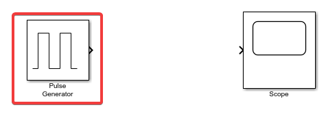
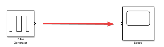
8.Connect the two blocks as shown below
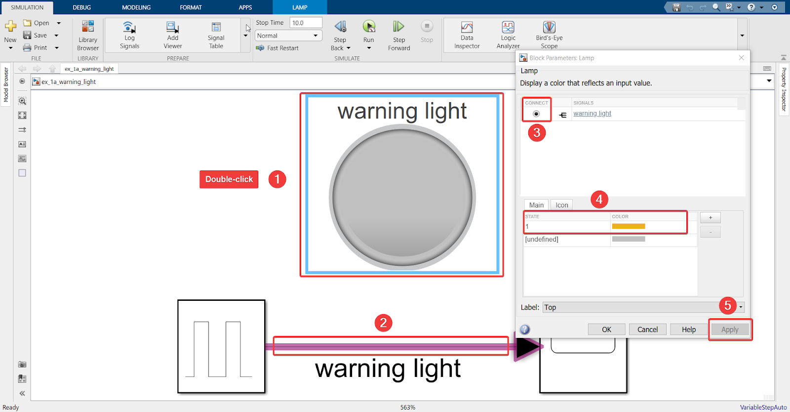
9.Set conditions for the lamp
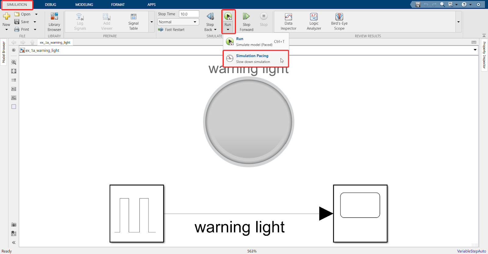
10. Activate a paced simulation under Run > Simulation Pacing > Enable Pacing
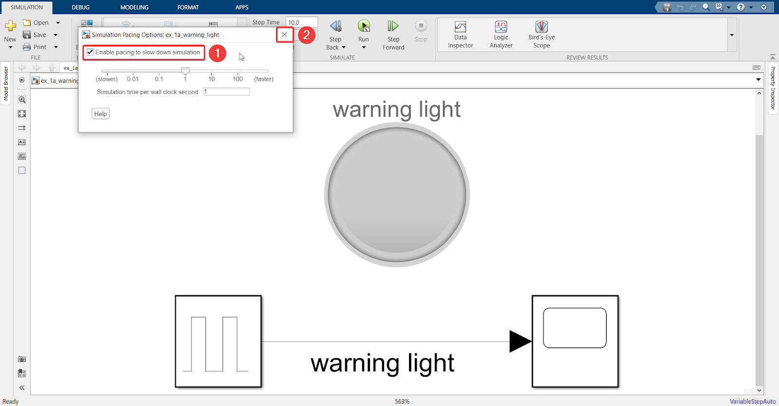
Explanation
Activating “Enable pacing to slow down simulation” will run the simulation in real-time. For example, if the “Stop Time” is set to 10 seconds, the simulation will run for 10 seconds as well.
11. Click Run
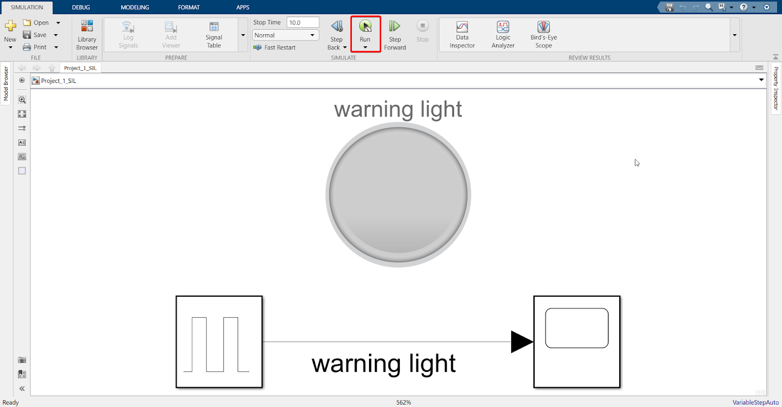
12. Result
As we can see, the warning light transitions between ON (‘1’) and OFF (‘0’).
Hardware in Loop (HIL) simulation
Since SIL is working, we can now move on to HIL simulation.
HIL is used to test the software on hardware repeatedly in a loop. This includes testing different situations and checking if the hardware is working without problems.
For more information, you may see: Basics of Hardware-In-The-Loop simulation - MATLAB & Simulink
Hardware setup
Once the hardware is set up, some modifications need to be made to the model in order to test it through the HIL process. This is where we will see the power of Waijung and MBD.
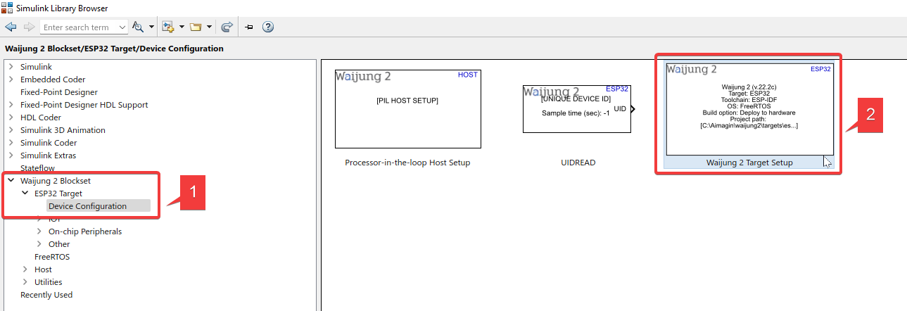
1.Go to ‘Library Browser’ > Waijung 2 Blockset > ESP32 Target > Device Configuration > Import ‘Waijung 2 Target Setup’ block into the model

For more information on this block, please check Waijung2 target setup block
2.Go to ‘Library Browser’ > Waijung 2 Blockset > ESP32 Target > On-chip Peripherals > IO > Import ‘Digital Output’ block into the model
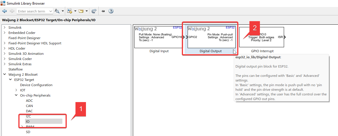
For more information on this block, please check Digital output block
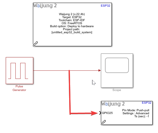
3.Set up the model as shown below
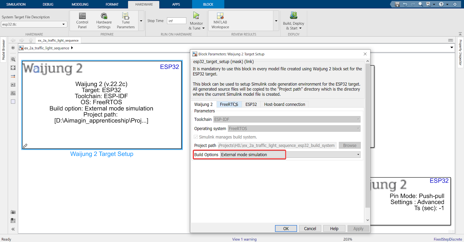
Explanation of External Mode simulation
i.For HIL testing, usage of an ‘External Mode simulation’ creates a communication channel between the Simulink model and the hardware (ESP32 in this case). When in ‘External Mode’, you can tune your parameters and watch the hardware respond to those changes in real-time.
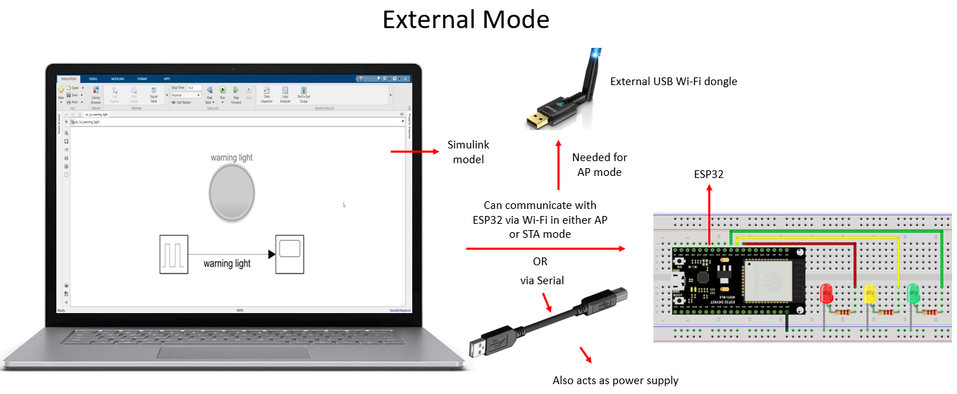
ii.Once ‘External Mode’ is enabled (shown in Step 3.1), Simulink can communicate with the ESP32 over WiFi Station (STA) / WiFi Access Point (AP) mode, and also over Serial.
iii.ESP32 microcontrollers have Wi-Fi capabilities, so when we deploy the ESP32 board as an access point (AP), other Wi-Fi devices (such as an external USB dongle) can connect to our board wirelessly. With WiFi STA mode, however, the ESP32 simply connects to the specified access point. With Serial, data is transferred via UART protocol.
A diagram to summarize how External Mode works
If you are interested to know more about External Mode, please refer to the following:
i.Host-Target Communication with External Mode Simulation - MATLAB & Simulink
ii.External Mode Simulation with TCP/IP or Serial Communication - MATLAB & Simulink
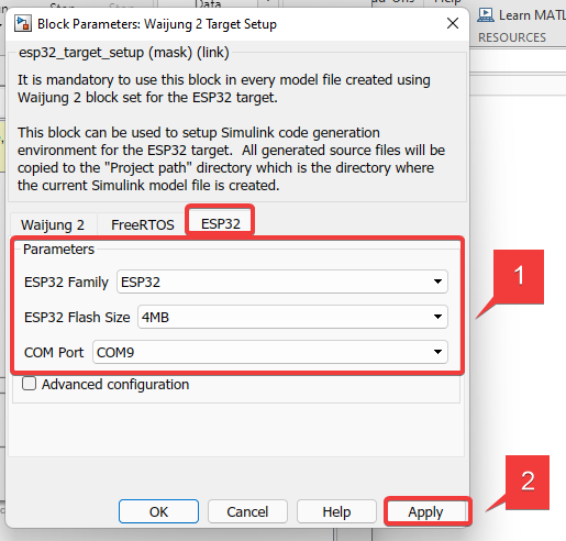
4. When you plug in your ESP32 to your computer, the following parameters will be automatically detected.
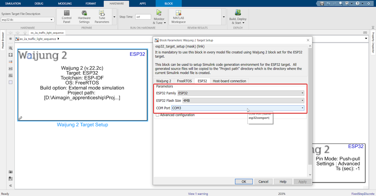
Note: Make sure to check your ESP32 datasheet to confirm your ‘Flash Size’ to avoid any errors. Also, confirm if the COM Port selected is of your ESP32.
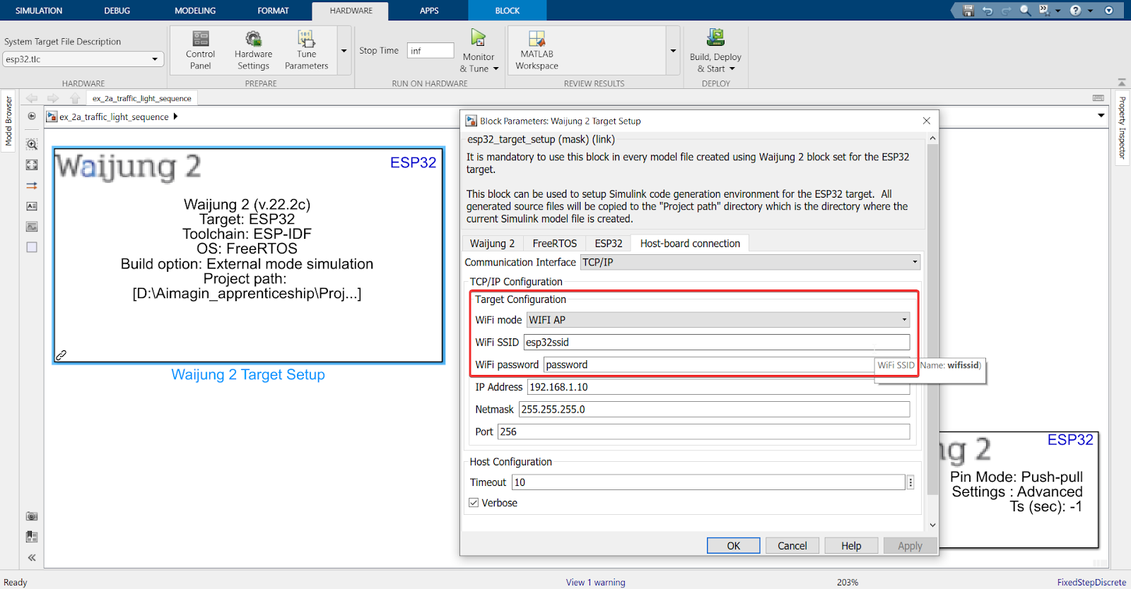
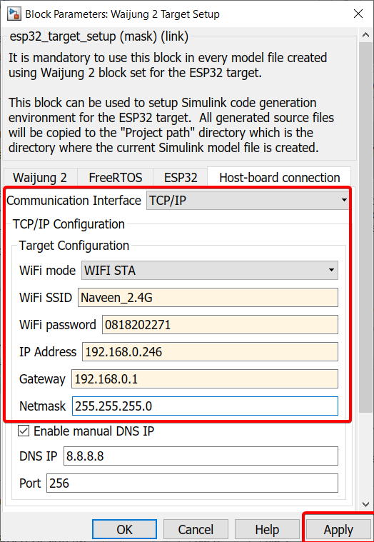
5. Set WiFi and password to make your ESP32 an access point
OR
In the Host-board connection tab, you can set up the WiFi Station Mode by using the SSID and password that your computer uses to connect to the internet.
Note: All ESP32 boards only support 2.4GHz bandwidth (except the recently released ESP32-C5 which also supports 5GHz), so make sure the WiFi you connect your ESP32 board to in WiFi STA mode lies in the 2.4GHz frequency range
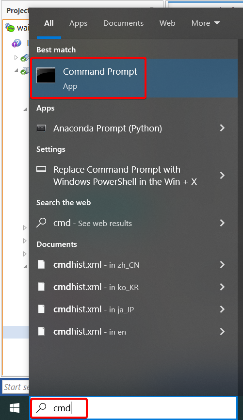
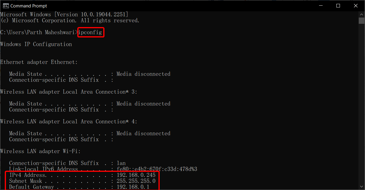
For the IP address, Gateway, and Subnet mask, please search for "command prompt" or "cmd" and type "ipconfig" to find the configurations and input them into the target setup.
Note: For the IP address, choose any number between 0 to 255 for the last 3 digits, except the IPv4 address listed in command prompt (since that is the IP address assigned to your computer).
OR
In the Host-board connection tab, select Serial as the communication interface. Check the datasheet of the board to find the tx and rx pins related to the UART module. Usually UART0 is connected to programming Serial port. For instance, this example is based on ESP32-WROOM board:
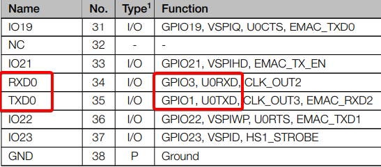
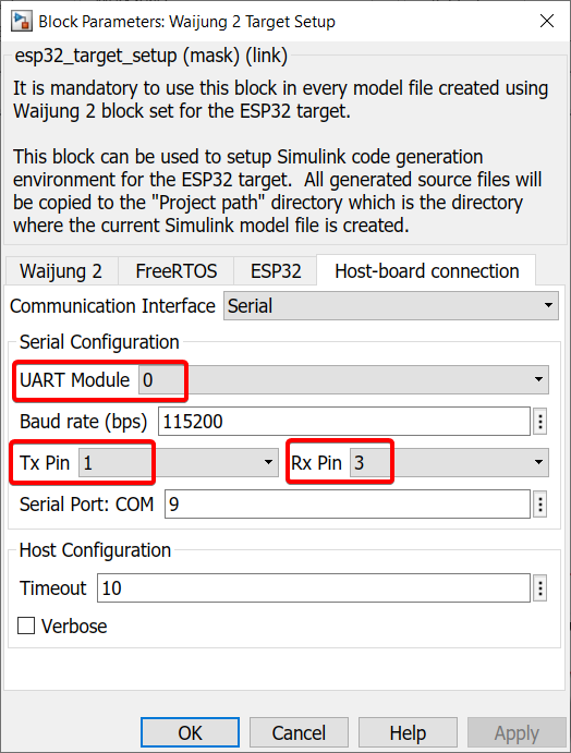
The above right image is from the ESP32-WROOM datasheet where UART0 module's transmitter (Tx) and receiver (Rx) are represented by GPIO 1 and GPIO 3, respectively. These are the configurations needed for the Waijung 2 target setup block in the above left image. Make sure you check your board's datasheet to find the correct Tx and Rx pins related to the UART module.
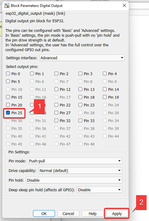
6. Select a ESP32 pin setting in ‘Digital Output’ block

7. Set the ‘Stop Time’ to ‘inf’ so you can test different situations in this HIL process by making changes on your software and viewing it in real-time on your hardware.
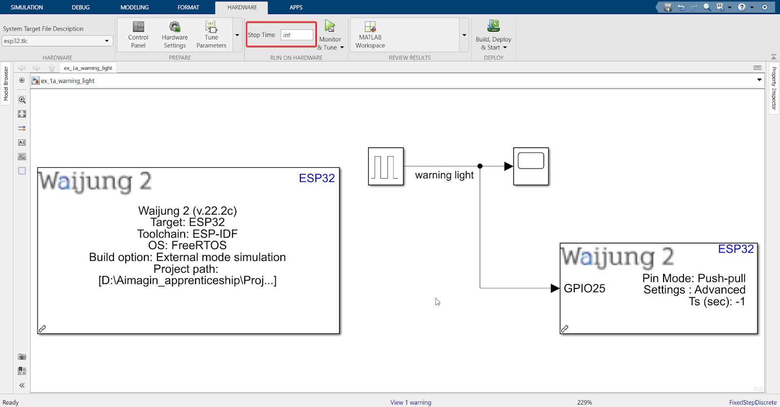
Explanation: The lamp has been removed from the model because it does not serve a purpose when operating in External Mode.
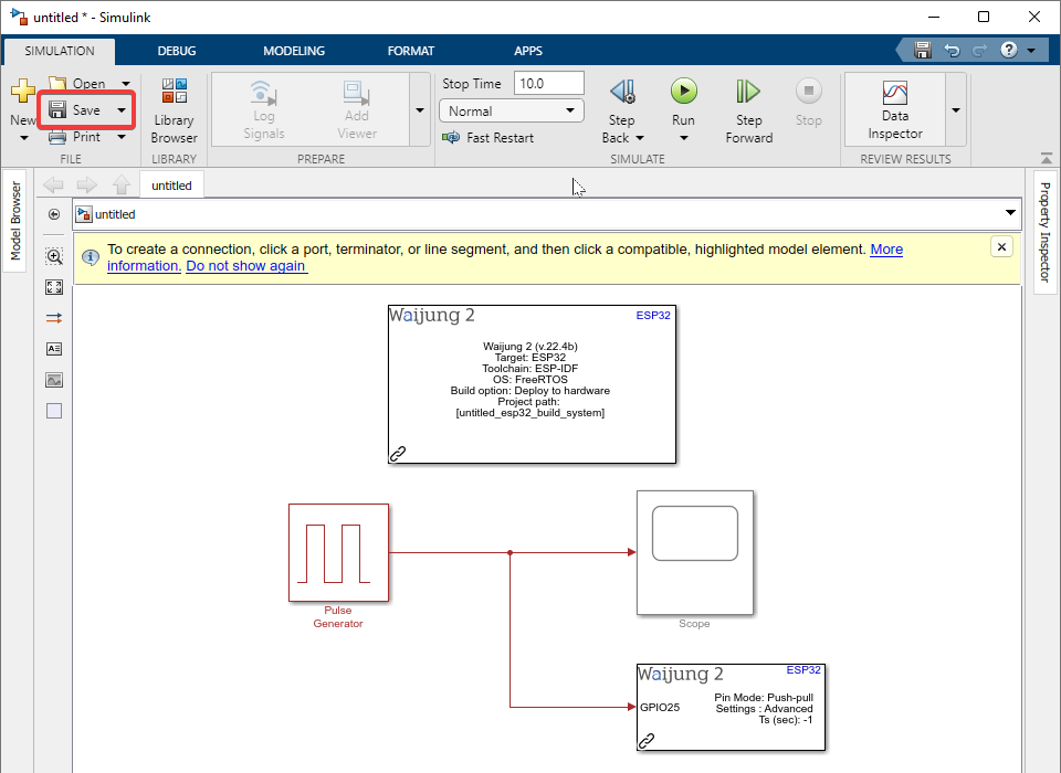
8. Save the model file before you build (file name must use English letters, numbers and underscore only, the first letter must be an English character, and the file name must not contain spaces or use letters/characters from another language)
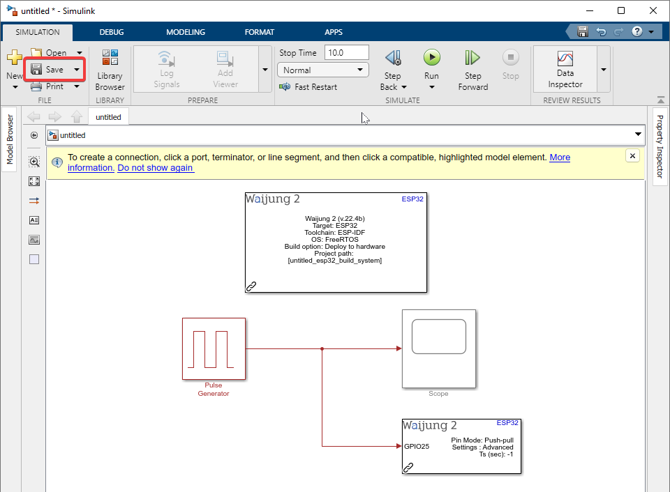
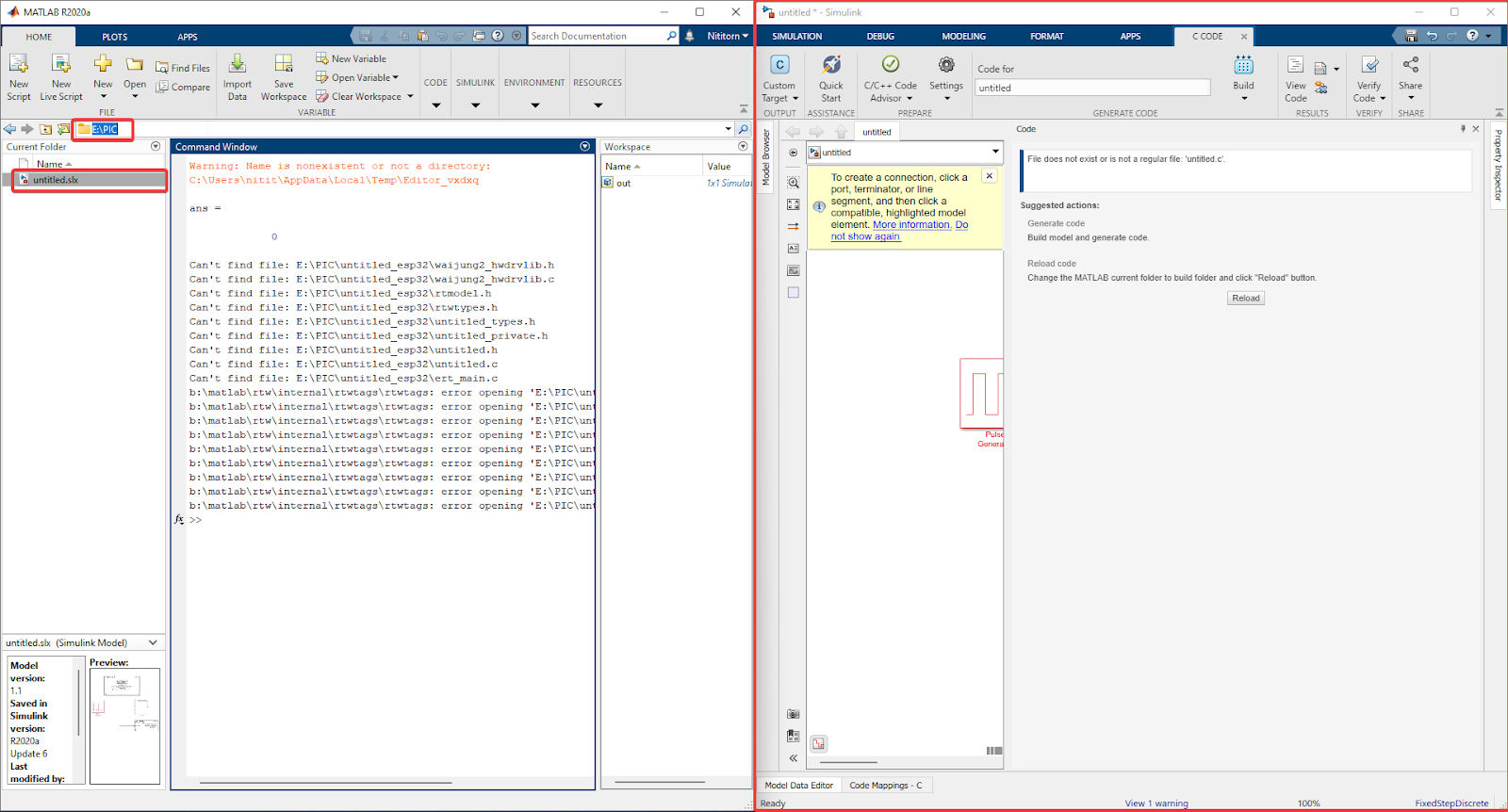
9. Make sure the MATLAB directory is set as the folder where your file will be stored.

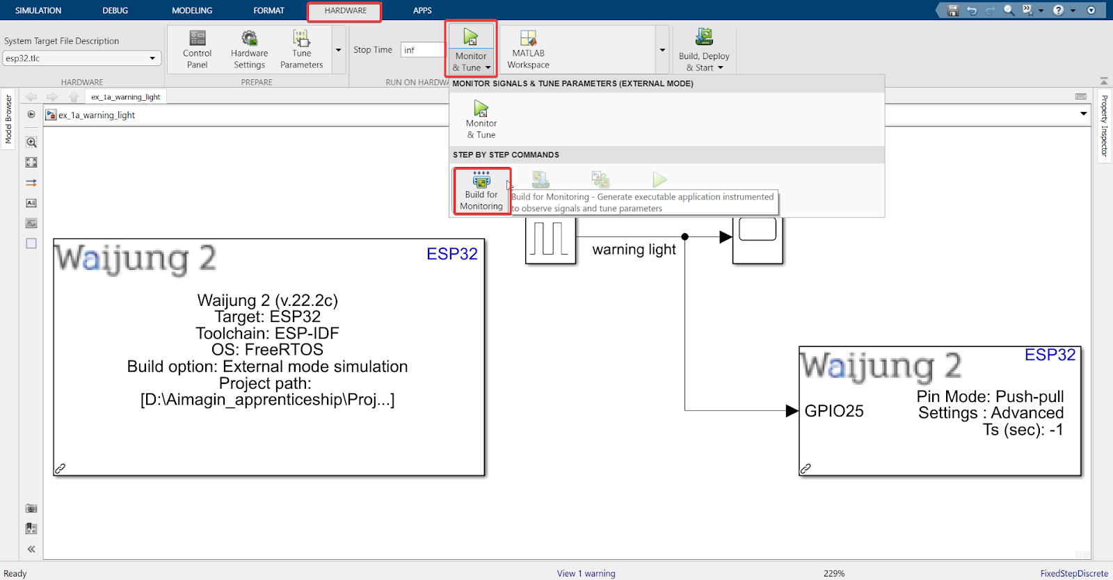
10. Go to the ‘Hardware’ Tab > Monitor & Tune > Build for Monitoring
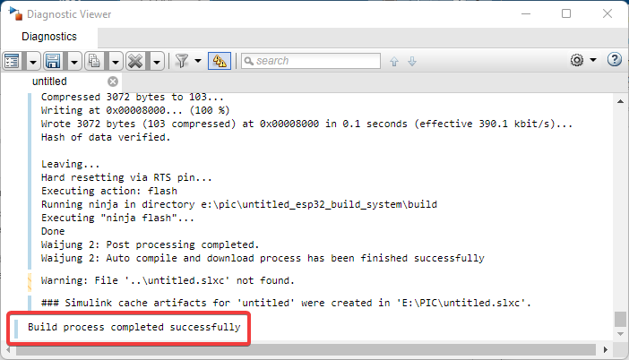
Note: Steps 11 and 12 are for users who are using External Mode via WiFi AP configuration. For WiFi STA or Serial, please skip to Step 13.
11. After the build process is complete, connect the USB Wi-Fi dongle to your computer to allow real-time connection between Simulink and ESP32.
12. Go to ‘Wi-Fi 2’ through your computer > connect to the access point created by the ESP32 using the SSID and password that was set in the Waijung 2 Target Setup block (in Step 5).
Finally, go to the ‘Hardware’ tab > Control Panel > Connect > OK
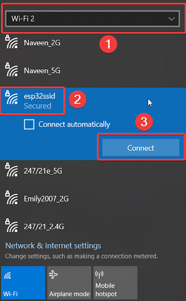
Note: Once you press the “Connect” button, you do not need to wait to see the word “connected”. You can move on to the next step.
13. Finally, go to the ‘Hardware’ tab > Control Panel > Connect > OK
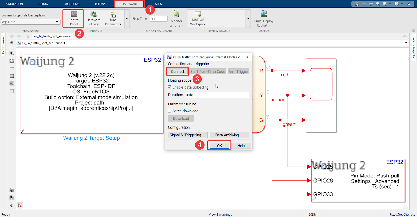
14. Result
As we can see, the hardware is now working together with the software. While HIL is running, you can try changing conditions such as ‘Period’ or ‘Pulse Width’ in the ‘Pulse Generator’ block to immediately see the hardware respond to those changes.
Stand-Alone (SA)
So far, we have learnt how to do SIL and HIL.
We will now see how to construct a ‘Stand-Alone (SA)’ operation, which means that the system can run offline on its own or without any external input.
An example of a SA system can be a TiVo box, which is used to record television programs.
1.Go to ‘Library Browser’ > Waijung 2 Blockset > ESP32 Target > Device Configuration > Import ‘Waijung 2 Target Setup’ block into the model
2.Go to ‘Library Browser’ > Waijung 2 Blockset > ESP32 Target > On-chip Peripherals > IO > Import ‘Digital Output’ block into the model

3.In the ‘Waijung Target Setup’ block, set up according to the following.
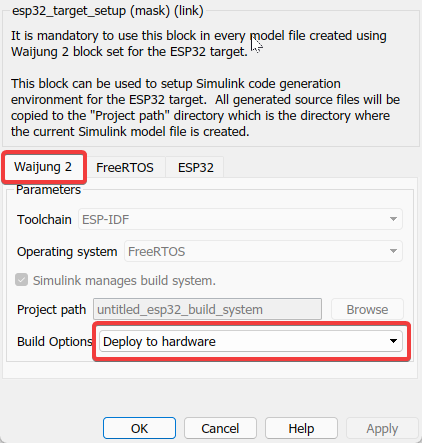
Summary of Deploy to Hardware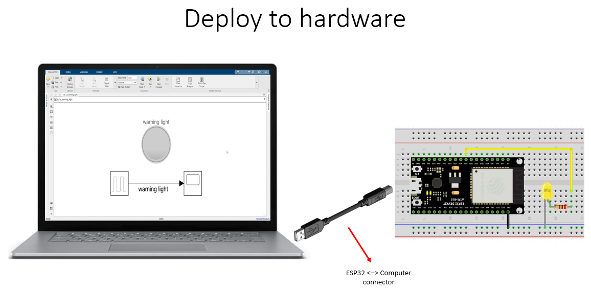
The ‘Deploy to hardware’ option means that the Simulink control system designed using blocks will be converted to C code, compiled, and uploaded to the ESP32. Once this process is complete, the ESP32 will operate offline and completely on its own.
4.Select a ESP32 pin setting in ‘Digital Output’ block
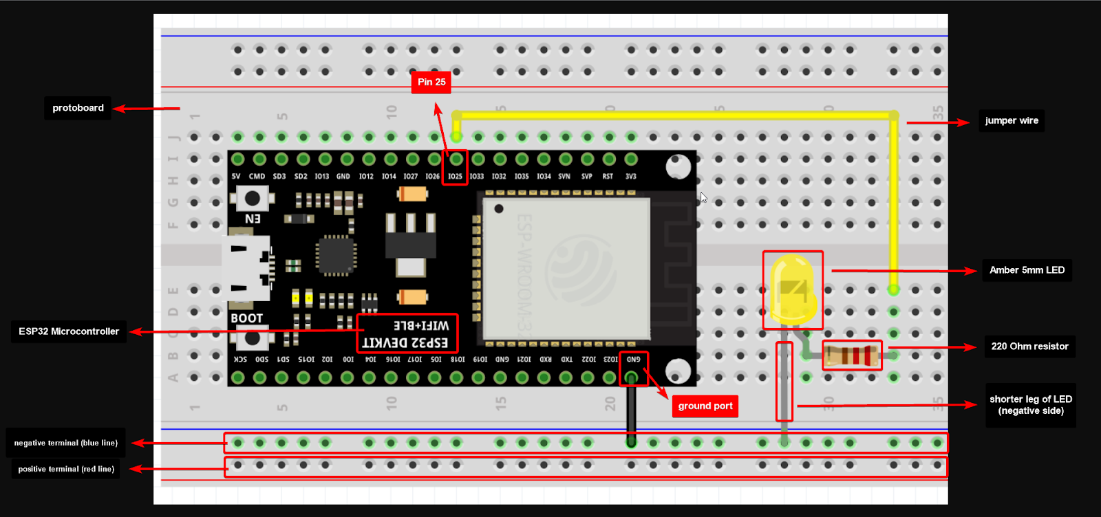
5.Connect according to the image shown below
6.Save the model file before you build (file name must use English letters, numbers and underscore only, the first letter must be an English character, and the file name must not contain spaces or use letters/characters from another language)
7.Make sure the MATLAB directory is set as the folder where your file will be stored
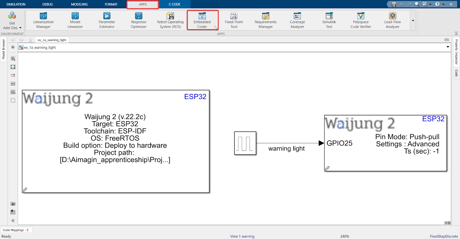
8.Go under ‘APPS’ and click ‘Embedded Coder’
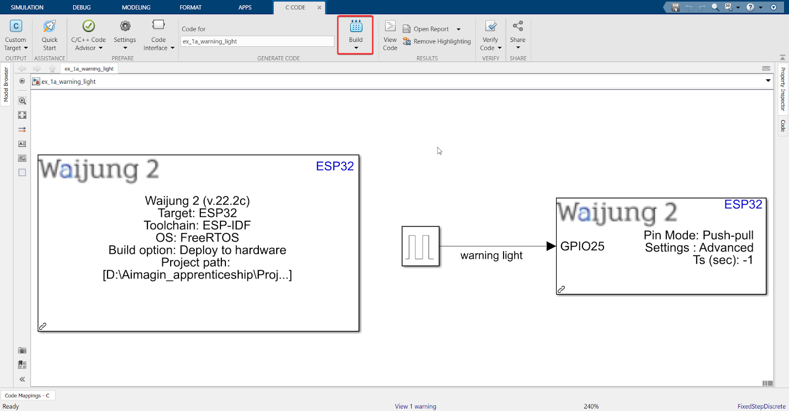
9.Click ‘Build’
Explanation
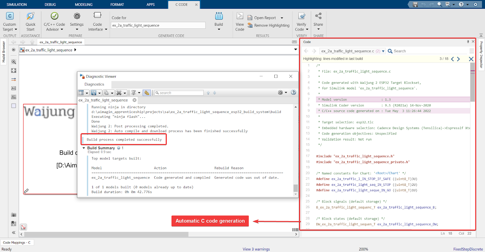
Automatic C code generation which has been deployed to the hardware. The ESP32 is not connected to Simulink anymore and will not be affected by any changes made in the model. To apply any changes to the board, the model will have to be rebuilt again.
Note: Automatic C code generation is not available with Waijung 2’s Standard or Professional License. It is only available with a Commercial License.
For more, please check Waijung2 Licenses
10.Result
This is the end of this tutorial.
Developing embedded control systems is a complex and expensive task, but notice how simple it becomes with the combination of Matlab, Simulink, and Waijung 2.
With just a few clicks and without writing a single line of code, you have been able to work on a real-life situation through connecting blocks together. You have also been able to test it on hardware that you can afford. This is the power of MBD and Waijung.
If you are interested in applying your learning further, you can test yourself with an exercise.
Exercise
In addition to the yellow LED, add 2 more LEDs and test them with different pulse widths (for example: green is ON for 1 sec, OFF for 2 sec & red is ON for 2 sec, OFF for 1 sec). Conduct SIL, HIL, and SA.