Project description
1.In this tutorial, you will perform HIL simulation for the controller model you designed in Exercise 6 to see on real hardware how:
a.When in On mode, the LED will continue to be turned on regardless of the threshold or the surrounding light level detected by a LDR sensor (manual override). Only brightness can be varied.
b.When in Auto mode, the LED will automatically turn on/off according to the set threshold and the surrounding light level. Brightness can also be varied.
c.When in Off mode, the LED will continue to be turned off regardless of the threshold or the surrounding light level (manual override).
Learning objectives
In this tutorial you will learn:
1.How to read LDR using Waijung 2 Analog to Digital Converter (ADC) block
2.How to drive LED using Waijung 2 Digital to Analog Converter (DAC) block
3.How to monitor signals and tune parameters in real-time using HIL simulation (External Mode) with real hardware (ESP32)
4.How to use Simulink Dashboard components to control parameters in real-time
Required hardware
No. |
Item |
Picture |
Quantity |
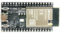
1 |
ESP32 with USB cable |
|
1 |
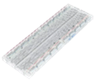
2 |
Protoboard (830 points) |
|
1 |
3 |
Jumper Wire Male-Male |
|
4 |
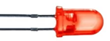
4 |
Red 5mm LED |
|
1 |
5 |
Resistor 220 Ohms |
|
1 |
6 |
Resistor 2k Ohms |
|
1 |
7 |
LDR sensor |
 |
1 |
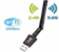
8 |
USB Wi-Fi dongle (only necessary if you need to use External Mode in WiFi AP configuration) |
|
1 |


Hardware setup
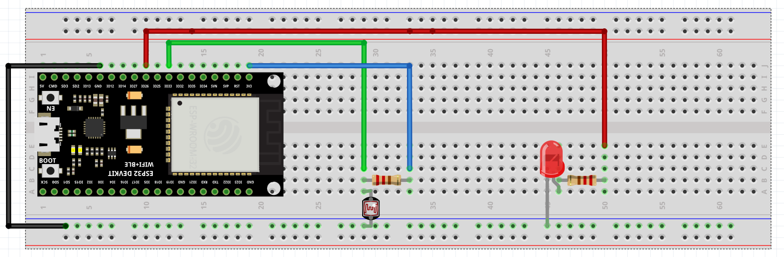
Tips and tricks to build HIL model:
1.From Exercise 6 SIL model, replace simulated analog input (Slider) with Waijung ADC block (represents input from LDR).
2.Replace analog output signal with Waijung DAC block (represents LED brightness output).
3.Rotary switch as mode selector and Sliders for changing brightness and threshold setting will act as real-time control mechanisms.
Final result (click to view video):
1.As is evident, On and Off modes are manual override modes where set threshold or analog input from LDR does not matter.
2.However, in Auto mode, LED will be turned on when the surrounding is dark as long as set threshold does not exceed analog value of the LDR.
3.As soon as bright light is projected onto the LDR, ADC value reduces significantly and hence the LED turns off immediately.
4.If we set the threshold to a very low value, we can see that even with bright surroundings the LED will remain turned on.
Project file: HIL file