Introduction
This document will guide you through the process of creating your first program using Waijung 2. By the end of this tutorial you will be able to,
•Understand the fundamentals of Matlab Simulink development environment.
•Understand the fundamental steps in creating a model, building and uploading to the target microcontroller.
Required Hardware
You will require the following hardware.
1.An ESP32-DevKit.
2.One LED.
3.One 220 Ohm resistor.
4.Jumper wires.
Required Software
Please refer the System Requirements section.
Setup
Before moving forward with the rest of the tutorial, complete the following steps.
1.Download the Waijung 2 block set. Follow the How to get Waijung 2 documentation for more details.
2.Install the Waijung 2 software. Follow the Waijung 2 installation guide for more details.
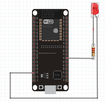
3.Setup the hardware as shown in the image below. The LED is connected to GPIO 2 pin of the microcontroller.
4.Connect the microcontroller to the computer via the USB port.
Let's Get Started!
The steps below will guide you through the process of creating a simple LED blink example.
Create a Model
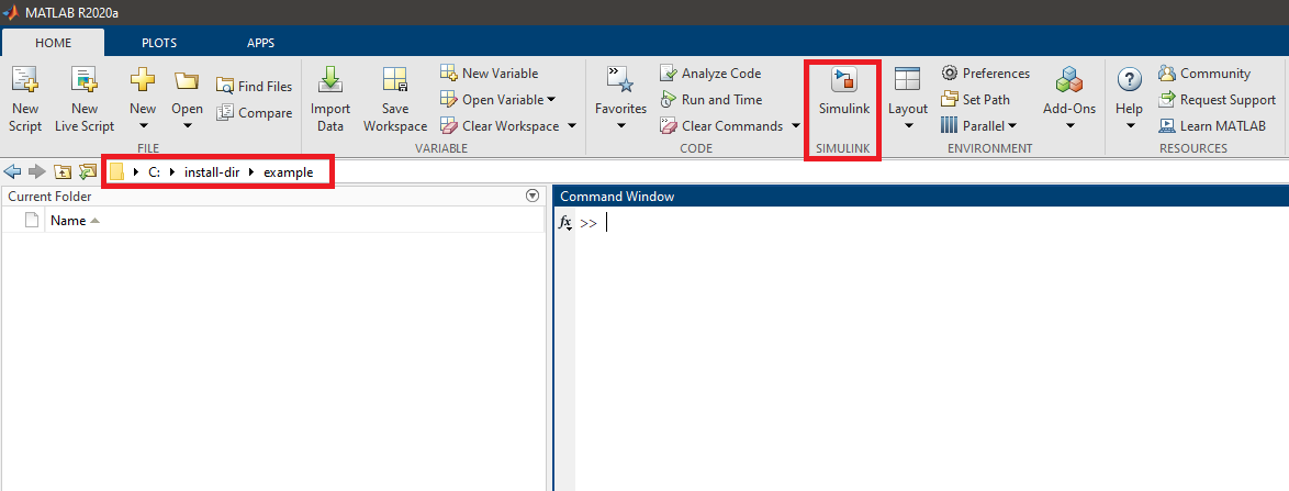
1.Open Matlab . Change the current folder to the directory where you want to create the model. Click Simulink.
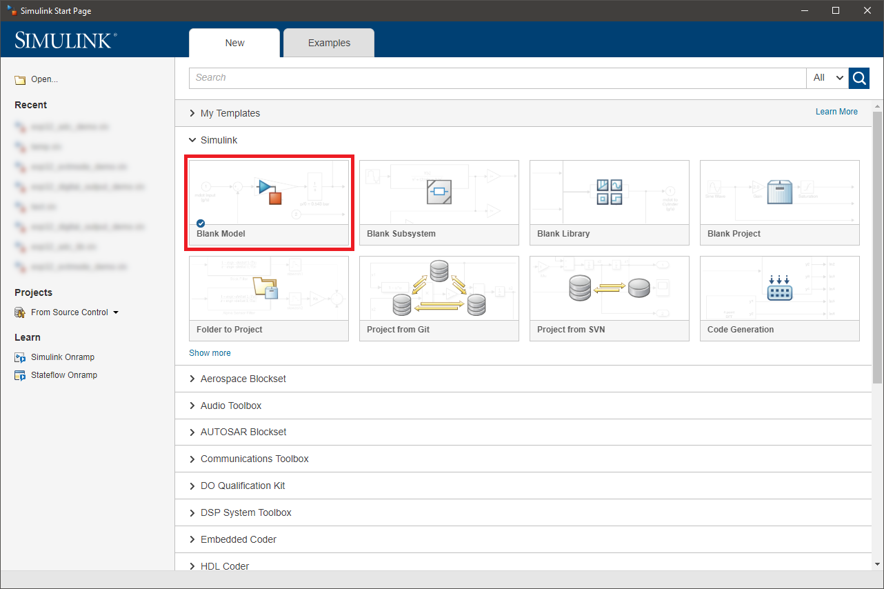
2.Click Blank Model. Save the model. Make sure the model name does not have spaces in it.
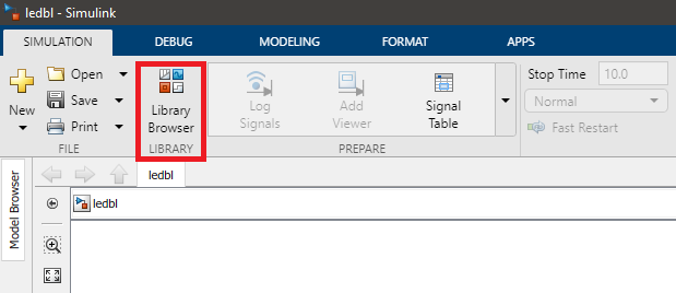
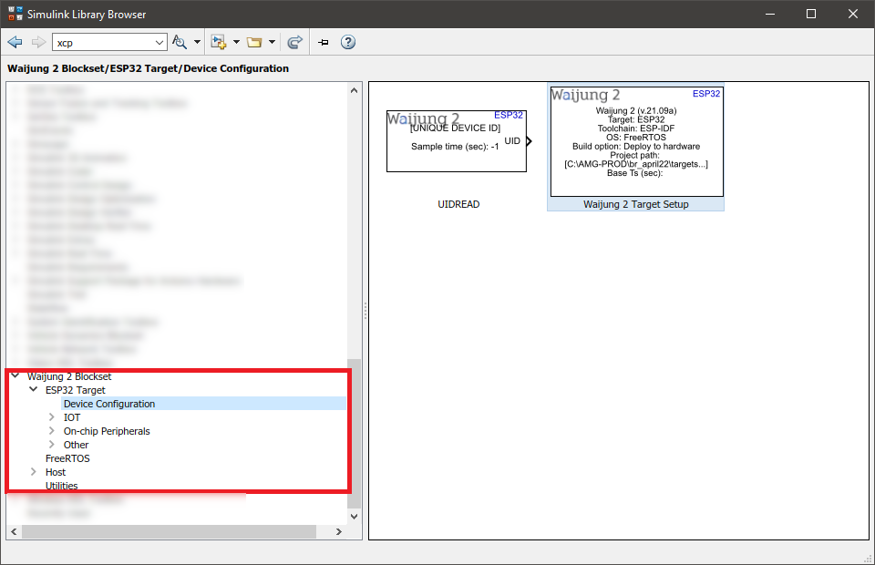
3.Next we will import the blocks related to this example. First, the Waijung 2 target setup block should be imported to the model. It is mandatory to add this block to your Simulink model files that intend to use Waijung 2 software. After the Waijung 2 installation, the block set will be available in the Library Browser. You can use the library browser to import Waijung 2 blocks to your workspace.
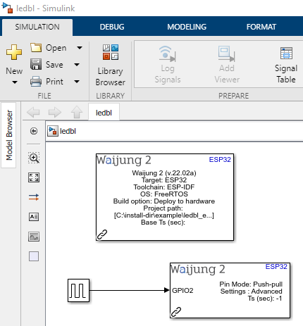
4.Next, import the following blocks to the model by following the same procedure explained in the previous step.
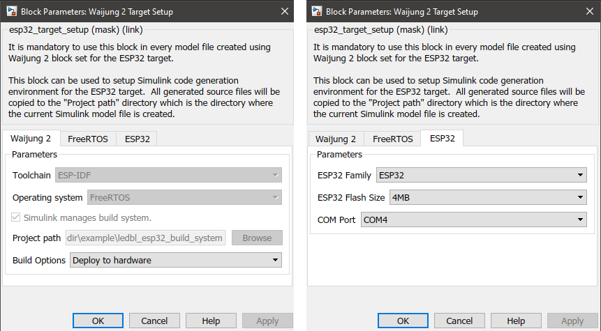
5.Double click on the block to open the block mask of each and every block. The block mask can be used to configure the block according to your preference. Open the block mask of each block in the above model and change the following configurations.
a.Waijung 2 Target Setup block mask
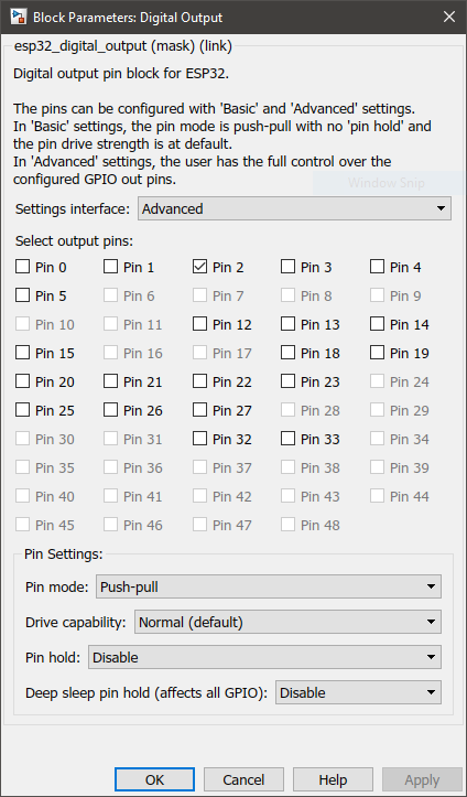
b.Digital Output block mask
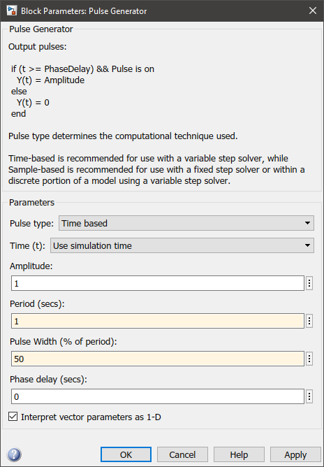
c.Pulse generator block mask
Build and Upload the Model to Your Microcontroller
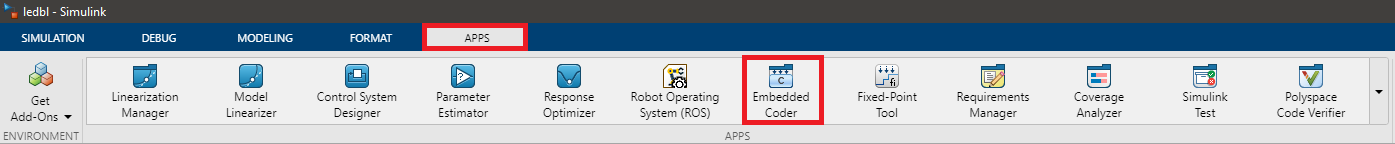
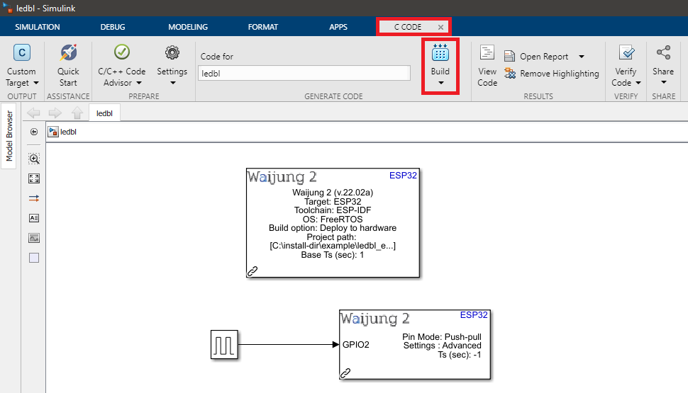
1.Finally, we can start building the program. Go to APPS tab and click Embedded Coder. After the C CODE tab opens, click the drop down menu and click Build. Do NOT click Generate Code.
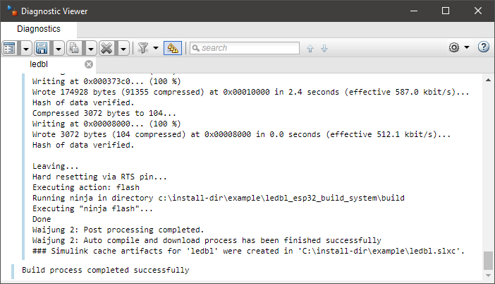
2.Once you click Build, Waijung 2 will start generating C code for your model and upload it to the board. You will be able to monitor the progress using the Diagnostic Viewer. Wait for the build process to complete.
Results
The LED will start blinking at a frequency of 1 Hz.
Additional Information
In case the user wants to monitor run time serial data, free serial monitor software such as PuTTY and Docklight can be used. Please make sure the correct COM Port and the BaudRate of 115200 is used.