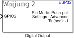
How this block appears in a Simulink model?
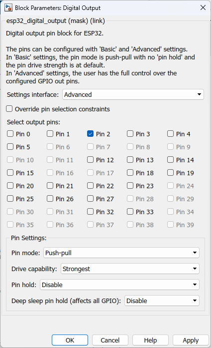
What can be configured?
Configuration Parameter |
Selectable Option/Value |
Description |
Settings interface |
Basic--Advanced |
Allow user to adjust the level of control over the specified pins. |
Override pin selection constraints |
Check-uncheck |
To enable the pins in "Select output pins" |
Select output pins |
Pino 0 to Pin 34 |
Select the output pins to be configured. |
Pin mode |
Push pull--Open drain |
For open drain mode internal or external pull up/down should be configured separately. |
Drive capability |
Weak--Decent--Normal--Strongest |
Select drive strength of the pins. |
Pin hold |
Enable--Disable |
Even though the GPIO pad hold function works in both input and output modes, it must be output capable GPIOs. If pad hold enabled: in output mode: the output level of the pad will be force locked and cannot be changed. in input mode: the input value read will not change, regardless of the changes of the input signal. The state of digital GPIO cannot be held during Deep-sleep, and it will resume the hold function when the chip wakes up from Deep-sleep. If the digital GPIO also needs to be held during Deep sleep, gpio_deep_sleep_hold_en should also be called. |
Deep sleep pin hold |
Enable--Disable |
When the chip is in Deep-sleep mode, all digital gpio will hold the state before sleep, and when the chip is woken up, the status of digital gpio will not be held. Note that the pad hold feature only works when the chip is in Deep-sleep mode, when not in sleep mode, the digital gpio state can be changed even you have called this function. |
INPUT/ OUTPUT Port
Port Name |
Port Type |
Date Type |
Range |
Description |
Pin <x> |
Scalar/Vector |
Any data type |
Expected values 0 or 1 |
<x> represents the selected pin number. For each selected pin in the mask, a separate port will be created. |
When to use this block?
This block implements Digital Output Module to generate digital output logic from the MCU pin.
How does this block work?
Each block is used to configure pins of a specified block.
You can have as many Digital Output Blocks as you need in a model, to configure different pins of the MCU.
Demo
Demo file : esp32_digital_output_demo.slx
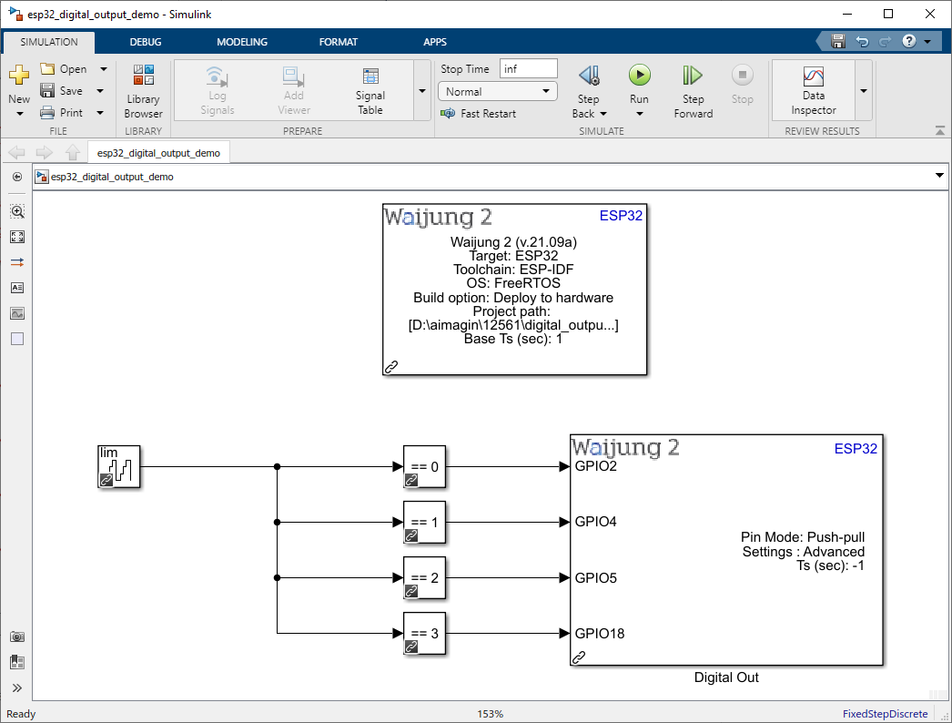
Description
This example shows how to use the Digital output block on ESP32. The Counter Limited block is used to control the four digital output pins. The upper limit of the counter is 4.
What should be happening?
Once the four digital output pins (GPIO2, GPIO4, GPIO5 and GPIO18) are connected to the LEDs and when the demo file is running on ESP32, the LEDs should turn on and off with the following sequence with 1s per state
1.State 1: GPIO 2 pin ON, all other OFF
2.State 2: GPIO 4 pin ON, all other OFF
3.State 3: GPIO 5 pin ON, all other OFF
4.State 4: GPIO 18 pin ON, all other OFF
5.State 5: all OFF