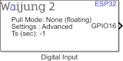
How this block appears in a Simulink model?
What can be configured?
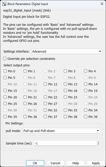
Configuration Parameter |
Selectable Option/Value |
Description |
Settings interface |
Basic--Advanced |
Allow user to adjust the level of control over the specified pins. |
Override pin selection constraints |
Check-uncheck |
To enable the pins in "Select input pins" |
Select input pins |
Pino 0 to Pin 39 |
Select the output pins to be configured. |
Pin mode |
None (floating)--Pull-up--Pull-down--Pull-up and Pull-down |
Only pins that support both input & output have integrated pull-up and pull-down resistors. Input-only GPIOs 34-39 do not. |
Sample time (sec) |
-1 (inherited) or specify |
Specify sample time of the block |
INPUT/ OUTPUT Port
Port Name |
Port Type |
Date Type |
Range |
Description |
Pin <x> |
Scalar/Vector |
uint8 |
Expected values 0 or 1 |
<x> represents the selected pin number. For each selected pin in the mask, a separate port will be created. |
When to use this block?
This block implements Digital Input Module to generate digital input logic from the MCU pin.
How does this block work?
Each block is used to configure pins of a specified block.
You can have as many Digital Input Blocks as you need in a model, to configure different pins of the MCU.
Demo
Demo file : esp32_digital_input_demo.slx
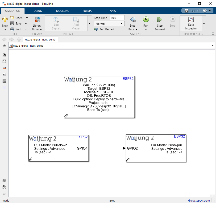
Description
This example shows how to use the Digital input block on ESP32. The state of the digital input pin (GPIO 4) will be represented on the digital output pin (GPIO 2).
What should be happening?
Once the digital input pin is connected to a button and the digital output pin is connected to a LED when running the demo on ESP32 , the LED turns on when the button is pressed and the LED turns off when the button is released.