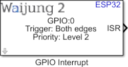
How this block appears in a Simulink model?
What can be configured?
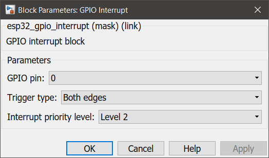
Configuration Parameter |
Selectable Option/Value |
Description |
GPIO pin |
0 to 39 |
Select GPIO pin to attach interrupt. |
Trigger type |
Rising edge--Falling edge--Both edges--Low level--High level |
Select the interrupt trigger. |
Interrupt priority level |
Auto--Level 1--Level 2--Level 3 |
Select the priority level of the interrupt |
INPUT/ OUTPUT Port
Port Name |
Date Type |
Description |
ISR |
Function-Call |
ISR port will output a logic ‘true’ signal that could activate a function-call subsystem in Simulink. |
When to use this block?
This block can be used to set up an Interrupt Service Routine (ISR) that could be triggered by an input signal to one of the digital pins.
How does this block work?
Depending on the input trigger configuration, when the specified trigger conditions are met the block will output a logic ‘true’ signal that could activate a function-call subsystem in Simulink.
Demo
Demo file : esp32_gpio_interrupt_demo.slx
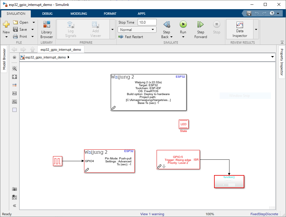
Description
This demo shows how to use the GPIO interrupt block. A simple GPIO toggle function for the GPIO2 is implemented using Digital output block. This function will be invoked in every rising edge signal on GPIO5. GPIO4 pin is used to generate a square-wave pulse to test the the GPIO5 pin.
Hardware Setup
The digital output pin (GPIO2) should be connected to a LED to observe the status of the pin.
What should be happening?
The status LED (GPIO2) will be changed in every 1s period.