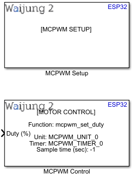
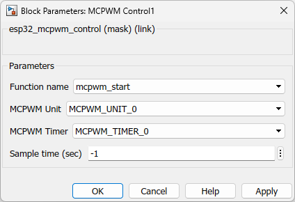
How this block appears in a Simulink model?
What can be configured?
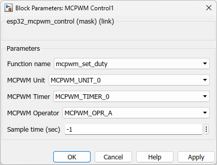
Function name - mcpwm_set_duty/ mcpwm_set_duty_in_us/ mcpwm_set_signal_high/ mcpwm_set_signal_low
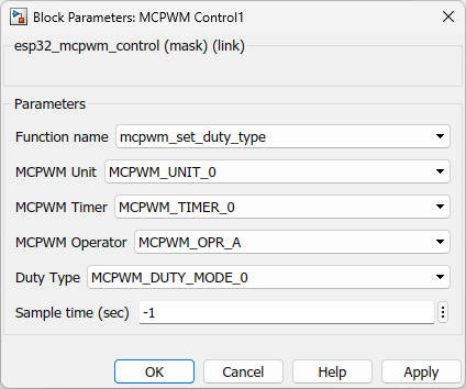
Function name - mcpwm_set_duty_type
Function name - mcpwm_start/ mcpwm_stop
Configuration Parameter |
Selectable Option/Value |
Description |
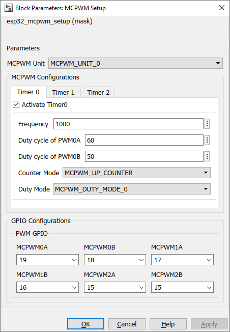
MCPWM Unit |
MCPWM_UNIT_0--MCPWM_UNIT_1 |
ESP32 has two MCPWM units and select one to be used |
Timer Tab |
Timer 0--Timer 1--Timer 2 |
Each tab has separate configuration parameters for each timer |
Activate Timer |
on--off |
Each timer if in use should be activated by this checkbox |
Frequency |
|
Select the PWM frequency |
Duty cycle of PWMxA/PWMxB |
|
This is the initial duty cycle of PWMxA/B. The user can change this value later using esp32_mcpwm_control block |
Counter Mode |
MCPWM_UP_COUNTER--MCPWM_DOWN_COUNTER--MCPWM_UP_DOWN_COUNTER |
Select counter mode. Check References for more details |
Duty Mode |
MCPWM_DUTY_MODE_0--MCPWM_DUTY_MODE_1--MCPWM_HAL_GENERATOR_MODE_FORCE_LOW--MCPWM_HAL_GENERATOR_MODE_FORCE_HIGH |
Select duty mode. Check References for more details |
Function name |
mcpwm_set_duty--mcpwm_set_duty_in_us--mcpwm_set_duty_type--mcpwm_set_signal_high--mcpwm_set_signal_low--mcpwm_start--mcpwm_stop |
Select function to control the output mcpwm_set_duty - to vary PWM’s duty by percentage mcpwm_set_duty_in_us - to vary PWM’s duty in microsecond mcpwm_set_duty_type - to alter the phase of the PWM signal mcpwm_set_signal_high/mcpwm_set_signal_low - to drive particular signal steady high or steady low with function mcpwm_start/mcpwm_stop - to drive the outputs with the PWM signal(The motor speed will be proportional to the PWM duty.) |
MCPWM Operator |
MCPWM_OPR_A--MCPWM_OPR_B |
Each Timer is automatically associated by the API to drive an Operator of the same index Select the operator that needs to proceed with the PWM out. Check References for more details. |
When to use this block?
This block is used to generate PWM signals to control motors.
How does this block work?
ESP32 has two MCPWM units which can be used to control different types of motors. Each unit has three pairs of PWM outputs.
MCPWM_SETUP is the configuration block that would enable user to configure everything in one MCPWM Unit. MCPWM_CONTROL consists various API's in the MCPWM driver by ESPRESSIF to drive the PWM signal. Therefore the user can have one MCPWM_SETUP block to configure all the components in a MCPWM unit and several MCPWM_CONTROL blocks to create a sequence to drive the motor.
Reference
Check Motor Control Pulse Width Modulator (MCPWM) driver documentation for ESP32 by ESPRESSIF
Demo:
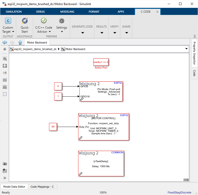
MCPWM Brushed motor demo
Demo file: esp32_mcpwm_demo_brushed_dc.slx
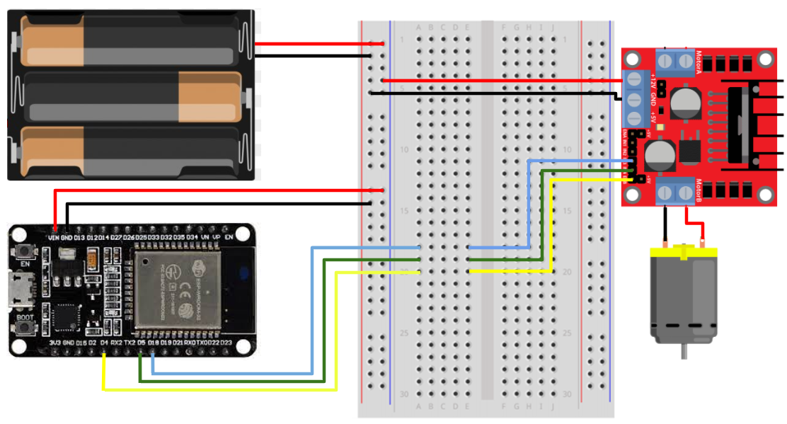
Required hardware:
•ESP32
•L298 motor driver
•DC Motor
•Power source
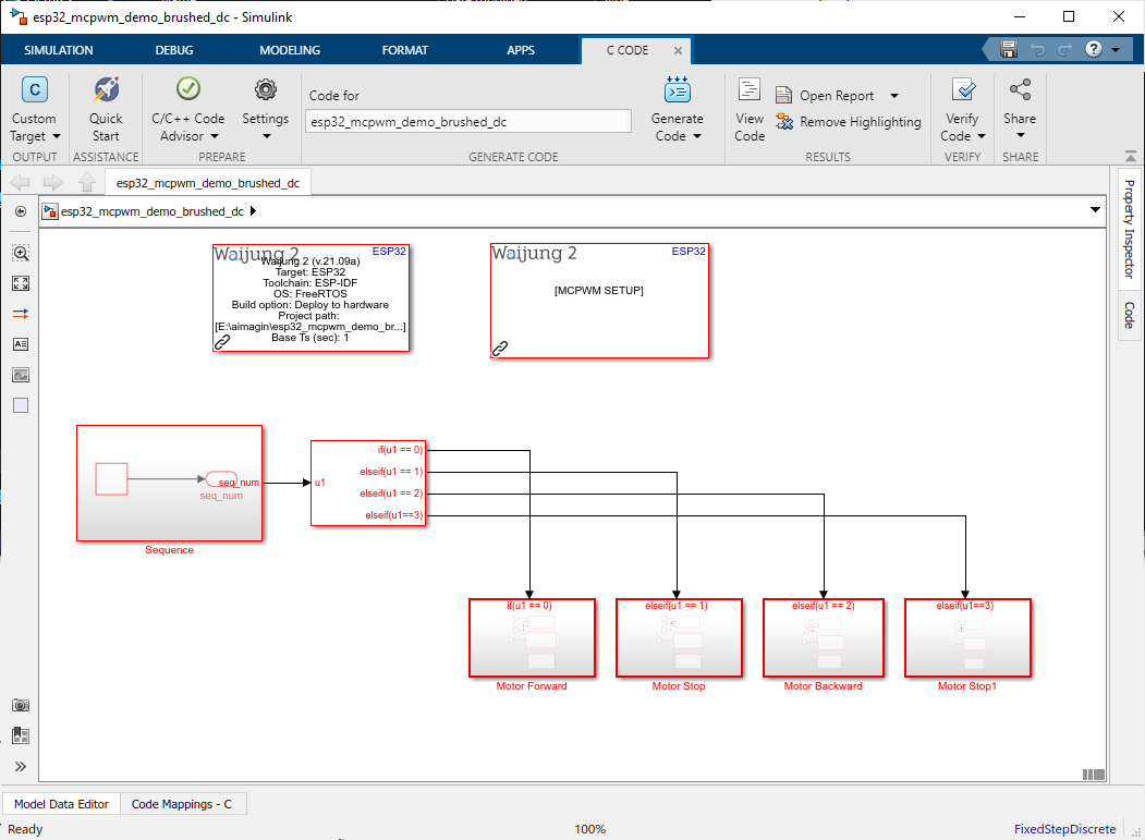
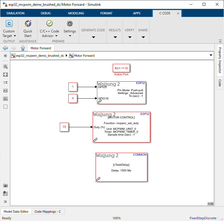
Pictures for each sub system:
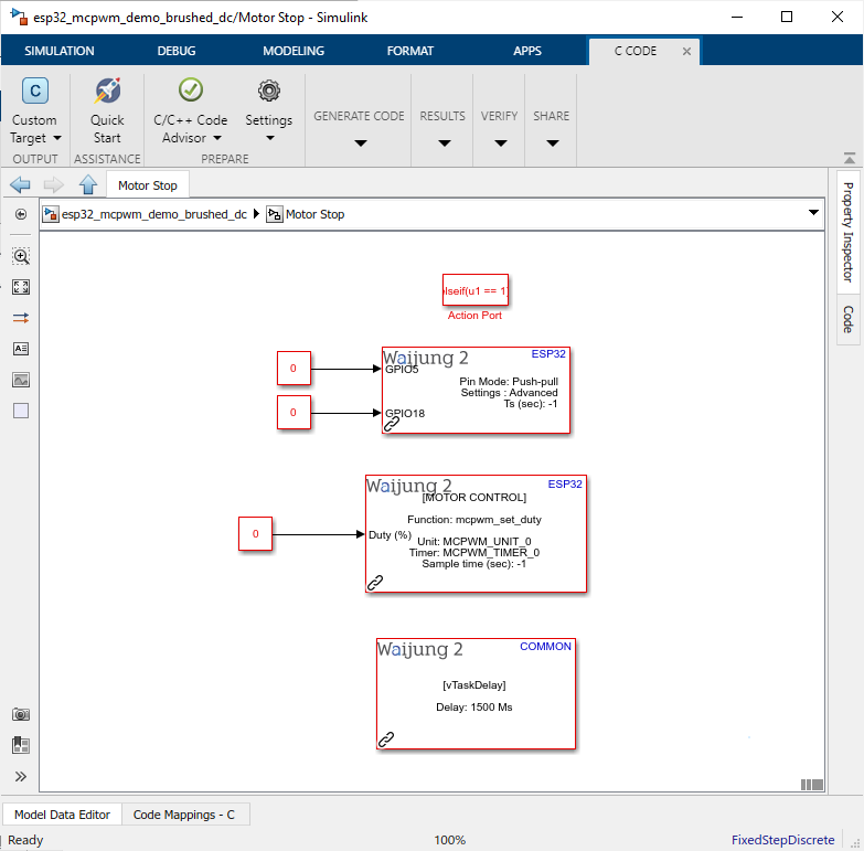
Description
This demo uses MCPWM Block to control a DC motor using a ESP32 module. Connect D4 pin to the "EN"(enable) pin in the L298 motor driver, and connect two directional pins(D5 & D18) to the "IN"(input) pins. Note that L298 motor driver have 2 H bridges select one side and continue wiring.
What should be happening?
DC motor will start moving forward for 1.5sec and backwards for another 1.5sec. In the middle of the motor direction movement there is a 1.5sec stop command to stop the motor. This will repeat as a loop
MCPWM Servo Motor demo
Demo file : esp32_mcpwm_demo_servo_motor.slx
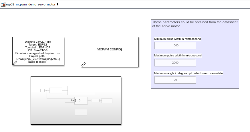
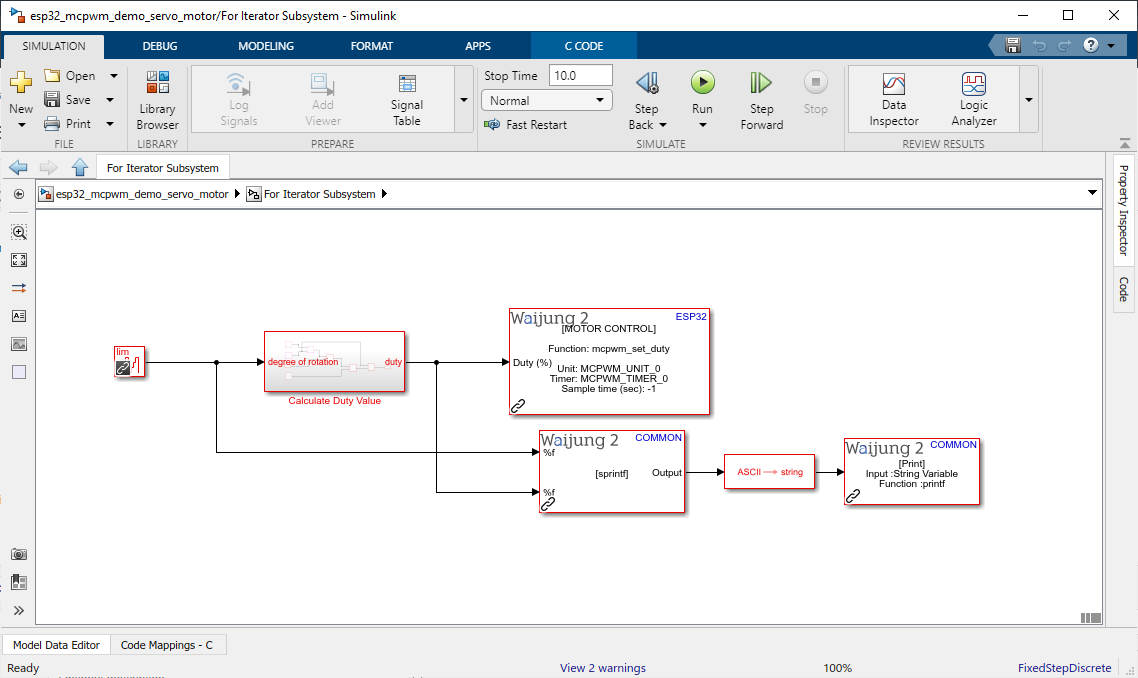
Description
This demo uses MCPWM block to control a servo motor using a ESP32 module. Please change the configurations according to the data sheet of your servo motor. String_processing_block and Print_block are there to see the what angle is set to the servo motor.
Hardware Setup
1.ESP32 module
2.Servo Motor
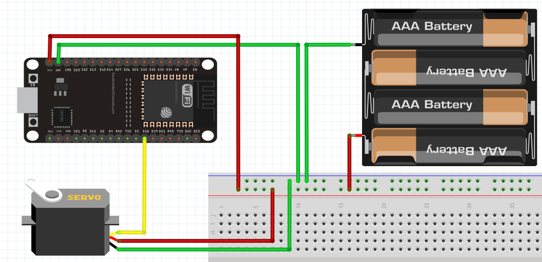
What should be happening?
The servo motor will start from 0 degree position and gradually increase to 90 degree position. Then it'll quickly come back to 0 degree position and repeat the process. User can also open the serial monitor to see what angles and calculated duties are given to the servo motor (baud rate: 115200).