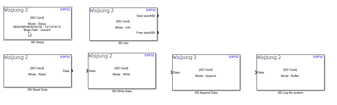
How this block appears in a Simulink model?
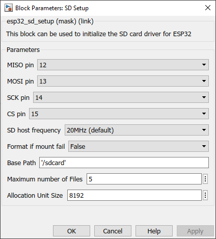
What can be configured?
SD Card Setup block
When the SPI master block is not available in the same BUS
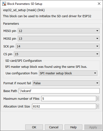
When the SPI master block is available and use the same pins (BUS)
Configuration Parameter |
Selectable Option/Value |
Description |
Chip select pin (CS) |
0 to 33 |
Select pin for CS |
Clock pin (SCLK) |
0 to 33 |
Select pin for SCLK |
Master read (MISO) |
0 to 33 |
Select pin for MISO |
Master write (MOSI) |
0 to 33 |
Select pin for MOSI |
SD host frequency |
20MHz (default)--10MHz |
Frequency for the SD host . Some ESP32 modules doesn't support default 20MHz frequency. |
Use configuration from |
SPI master setup block--SD card setup block |
If both SPI master setup and the SD card use the same bus(pins), select which configuration should be used to configure the SPI bus for both SPI master block and SD card. |
Format if mount fail |
True--False |
If FAT partition cannot be mounted, and this parameter is true, create the partition table and format the filesystem. |
Base path |
|
The block registers given FAT drive in VFS, at the specified base path. |
Maximum number of files |
|
maximum number of files which can be open at the same time |
Allocation unit size |
|
If ‘format_if_mount_failed’ is set, and mount fails, format the card with the given allocation unit size. Must be a power of 2, between sector size and 128 * sector size. For SD cards, sector size is always 512 bytes. |
SD Card Read block
Configuration Parameter |
Selectable Option/Value |
Description |
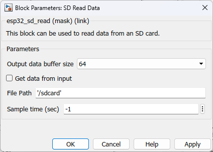
Output data buffer size |
32--64--128--256--512--1024--2048--4096 |
Select the expected number of characters to be read from SD card file. |
Get data from input |
Check-Uncheck |
Allow user to enter data though an input port |
File path |
|
The file path should follow the following convention /<Base path>/<filename>.<extention> |
Sample Time |
-1 (inherited) or specify |
Specify the sample time for the block |
INPUT/ OUTPUT Port
Port Name |
Port Type |
Date Type |
Description |
Data |
Vector |
uint8 |
The port outputs a character vector with the data written in the requested file in the SD card. |
SD Card Write
Configuration Parameter |
Selectable Option/Value |
Description |
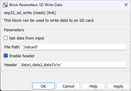
Get data from input |
Check-Uncheck |
Allow user to enter data though an input port |
File path |
|
The file path should follow the following convention /<Base path>/<filename>.<extention> |
Enable header |
Check--Uncheck |
This is used to add a header in the first line of the file when creating a new file. All the log data will be appended from the 2nd line of the file onwards. |
Header |
|
To enter the header values |
INPUT/ OUTPUT Port
Port Name |
Port Type |
Date Type |
Description |
Data |
Vector |
uint8 |
Feed in a character vector with the data to be written. |
SD Card Append
Configuration Parameter |
Selectable Option/Value |
Description |
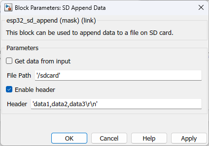
Get data from input |
Check-Uncheck |
Allow user to enter data though an input port |
File path |
|
The file path should follow the following convention /<Base path>/<filename>.<extention> |
Enable header |
Check--Uncheck |
This is used to add a header in the first line of the file when creating a new file. All the log data will be appended from the 2nd line of the file onwards. |
Header |
|
To enter the header values |
INPUT/ OUTPUT Port
Port Name |
Port Type |
Date Type |
Description |
Data |
Vector |
uint8 |
Feed in a character vector with the data to be appended. |
SD Log file system
Configuration Parameter |
Selectable Option/Value |
Description |
||
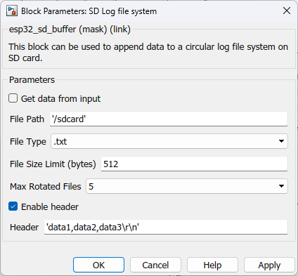
Get data from input |
Check--Uncheck |
Tick the check box to get all the parameters from input ports instead of configuring in the block mask. |
||
File path |
|
The file path should follow the following convention /<Base path>/<filename>.<extention> |
||
File type |
|
Select the file data type |
||
File size limit |
|
Specify the byte size of each file |
||
Max rotated files |
|
Select the number of maximum files |
||
Enable header |
Check--Uncheck |
This is used to add a header in the first line of the file when creating a new file. All the log data will be appended from the 2nd line of the file onwards. |
||
Header |
|
To enter the header values |
INPUT/ OUTPUT Port
Port Name |
Port Type |
Date Type |
Description |
All input ports |
Vector |
uint8 |
|
When to use this block?
This block can be used to set up, read, write, append data to an SD card connected to an ESP32 microcontroller. For convenience, the driver is implemented on five blocks. Namely,
•SD Card Setup
•SD Card Read
•SD Card Write
•SD Card Append
•SD Log File System
It is mandatory to have the SD Card Setup block present in the model whenever the other blocks are used.
How does this block work?
•SD Card Setup: ESP-IDF uses the FatFs library to work with FAT filesystems. FatFs reside in the fatfs component.
•SD Card Read: The block reads the content saved in the specified file up to the buffer size limit and outputs the data from the output port.
•SD Card Write: The block search for the file name in the given path. If the filename already exists, it deletes that file and creates a new file with the same name, and writes the new data to that file. If the file name does not exist, it creates a new file and the data.
•SD Card Append: The block search for the file name in the given path. If the file name already exists, it opens that file and adds the new data to the file. If the file name does not exist, it creates a new file and the data.
•SD Log File System: This block can be used to setup a circular log file system. The maximum number of files which can be created and the files size for those files can be configured. Once it configured the system starts log data from first file up to given files size. Once it filled, it creates a new file and this will continue up to the given max rotated files. When it comes to the max rotated file count and once it is filled, the system moves to the first file and starts logging data from the beginning.
Demo
Demo file : esp32_sdcard_demo.slx (developed with ESP32 Wrover IE + External SD card adapter with SPI interface)
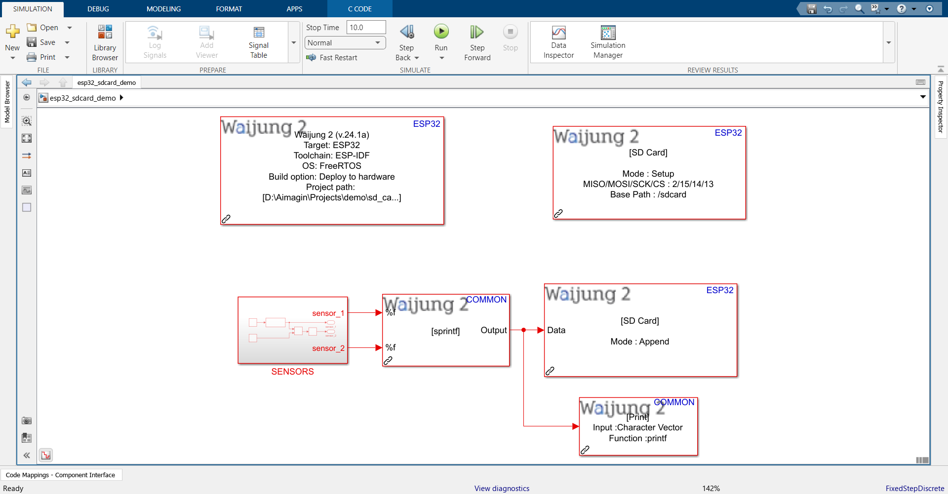
Description
This demo shows how to use the SD card block. In the model, the SENSORS subsystem is used to mimic two analog sensors. Each second the acquired data is logged into a CSV file on the SD card.
Note:
If you are using the aMG FiO Glide ESP32 board, it comes with an inbuilt SD card slot and you can simply import the SD Setup block without the need to change anything in the block mask. No jumper wires are needed to connect any pins. 3.3V should work.
On the other hand, if you are using an ESP32-family board with an external SD card adapter, please note that there are certain conditions and incompatibility issues that may occur with using an external SD adapter. You may need to check out this link. It states the default pins to use on ESP32 and other families in order to connect to SD card via SPI, the need to use lower clock frequency (10MHz). You may also need to use a 5V input from the ESP32 instead of 3.3V.
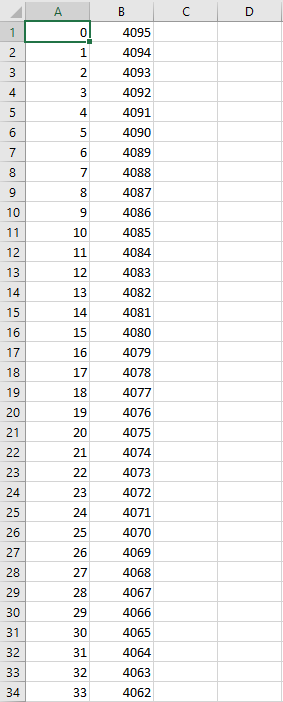
What should be happening?
Once the SD card is inserted into the target module and the program is uploaded, the data will be logged to the sd card. After about 10 seconds, remove the SD card and plug it into a Desktop or Laptop computer to view the data from the data.csv file created by the program.