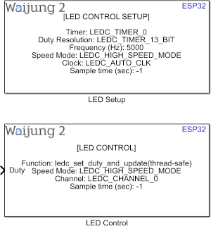
How this block appears in a Simulink model?
What can be configured?
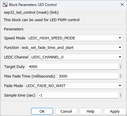
Function - ledc_set_fade_time_and_start
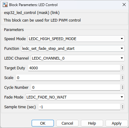
Function - ledc_set_fade_step_and_start
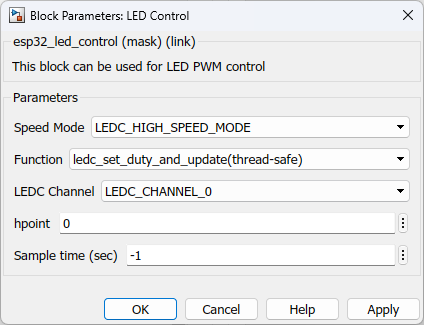
Function - ledc_set_duty_and_update(thread-safe)
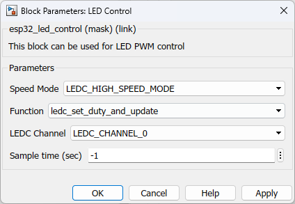
Function - ledc_set_duty_and_update
Configuration Parameter |
Selectable Option/Value |
Description |
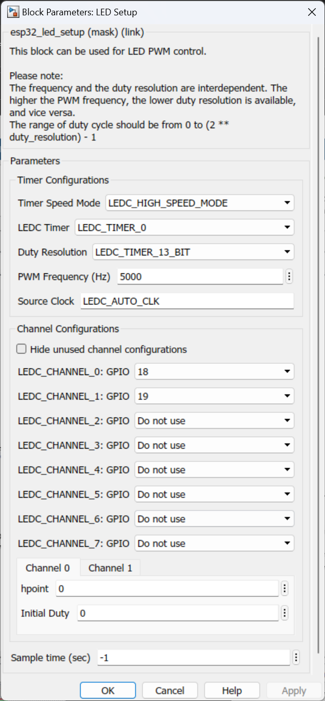
LEDC Timer |
LEDC_TIMER_0--LEDC_TIMER_1--LEDC_TIMER_2--LEDC_TIMER_3 |
Select the timer |
Duty Resolution |
LEDC_TIMER_1_BIT to LEDC_TIMER_20_BIT |
Select the duty resolution |
PWM Frequency (Hz) |
|
Specify the PWM frequency |
Timer Speed Mode |
LED_HIGH_SPEED_MODE--LED_LOW_SPEED_MODE |
Select the LEDC driver speed mode High Speed mode : this mode is implemented in hardware and offers automatic and glitch-free changing of the PWM duty cycle Low Speed mode : in this the PWM duty cycle must be changed by the driver in software. |
Source Clock |
|
If the value for this parameter is LEDC_AUTO_CLOCK, the clock will be selected automatically |
Hide unused channel configurations |
on--off |
The channels assigned Do not use will be hidden |
LEDC_CHANNEL_N: GPIO |
Do not use--0 to 48 |
Select the ledc output gpio pin |
hpoint |
|
The counter value when the output is set to high level |
Function |
ledc_set_fade_time_and_start--ledc_set_fade_step_and_start--ledc_set_duty_and_update--ledc_set_duty_and_update(thread-safe) |
The user can use any of the functions to manipulate the LED behavior. |
Target Duty |
|
Specify the target duty. The maximum of this parameter depend on the timer configurations. Check reference for more information |
Max Fade Time (milliseconds) |
|
Specify the time duration for the fade |
Fade Mode |
LEDC_FADE_NO_WAIT--LEDC_FADE_DONE |
Select fade mode |
Scale |
|
Controls the increase or decrease step scale when the ledc_set_fade_step_and_start function is selected |
Cycle Number |
|
Increase or decrease the duty every cycle_num cycles when the ledc_set_fade_step_and_start function is selected |
Port Name |
Port Type |
Date Type |
Description |
Duty |
Scaler |
uint32 |
To input the duty resolution |
When to use this block?
This block is designed to control LED intensity using PWM signals. This block could be used for other similar applications involving PWM signal generation as well.
How does this block work?
•The ESP32 family has 8 high speed channels and 8 low speed channels while ESP32-S2 has 8 low speed channels to generate LED PWM.
•There are four Timer modules to be selected.
•When the PWM frequency increases the resolution decreases.
•When setting up the this block, supported range of frequency and duty resolutions should be taken into account. The information can be found in the technical reference manuals of the respective microcontroller family provided by ESPRESSIF. You will find the commonly-used frequencies and resolutions for the ESP32 in the table below.
LEDC Clock Source |
LEDC Output (PWM) Frequency |
Highest Resolution |
APB_CLK (80 MHz) |
1 kHz |
1/80,000 (16 bit) |
APB_CLK (80 MHz) |
5 kHz |
1/16,000 (14 bit) |
APB_CLK (80 MHz) |
10 kHz |
1/8000 (13 bit) |
RTC8M_CLK (8 MHz) |
1 kHz |
1/8000 (13 bit) |
RTC8M_CLK (8 MHz) |
8 kHz |
1/1000 (10 bit) |
REF_TICK (1 MHz) |
1 kHz |
1/1000 (10 bit) |
Reference
Check LED Control (LEDC) driver documentation for ESP32 documentation of ESPRESSIF
Demo
Demo file : esp32_ledc_demo.slx
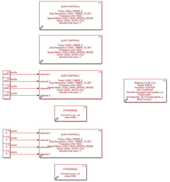
Description
This demo uses LEDC Block to configure four LEDs to repeat four sequences.
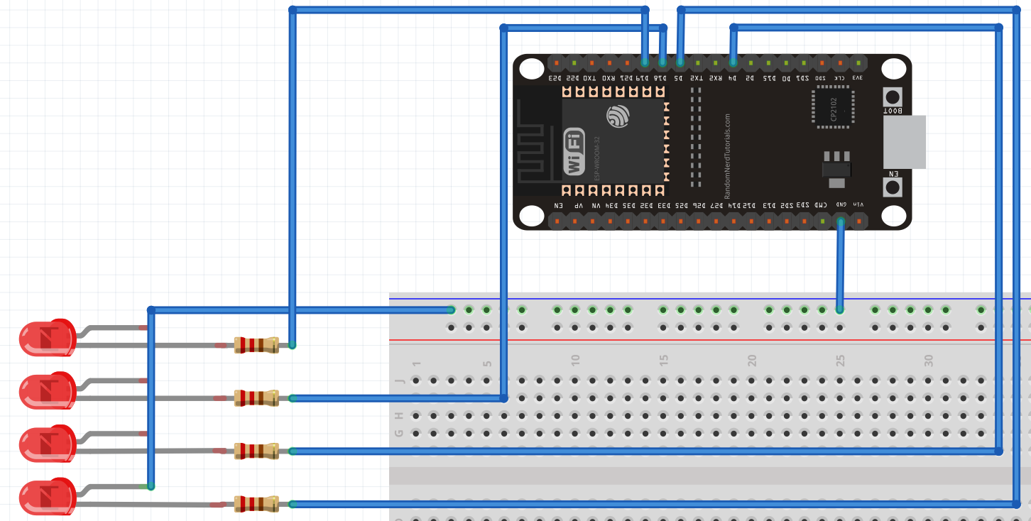
Hardware Setup
1.ESP32 module
2.4 LEDs
3.4 Resistors (1k ohm)
What should be happening?
The four LEDs will follow the four sequences below.
1.Gradually increase the intensity to LED ON state
2.Gradually decrease the intensity to LED off state.
3.Quick change to On state.
4.Quick change to OFF state.