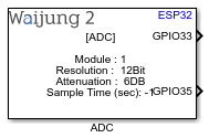
How this block appears in a Simulink model?
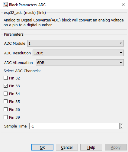
What can be configured?
Configuration Parameter |
Selectable Option/Value |
Description |
ADC Module |
1--2 |
The ADC driver API supports ADC1 (8 channels, attached to GPIOs 32 - 39), and ADC2 (10 channels, attached to GPIOs 0, 2, 4, 12 - 15 and 25 - 27). |
ADC Resolution |
9Bit--10Bit--11Bit--12Bit |
Specify the resolution. This value is: 4095 for 12-bits, 2047 for 11-bits, 1023 for 10-bits, 511 for 9 bits. |
ADC attenuation |
0DB--2.5DB--6DB--11DB |
Select attenuation (0db:100 mV ~ 950 mV, 2.5db:100 mV ~ 1250 mV, 6db:150 mV ~ 1750 mV, 11db:150 mV ~ 2450 mV) |
Select ADC channels |
|
Select channel pins |
Sample time (sec) |
-1 (inherited) or specify |
Specify the sample time |
INPUT/ OUTPUT Port
Port Name |
Port Type |
Date Type |
Description |
|---|---|---|---|
All output ports |
Scalar |
int16 |
These ports will be output ADC value corresponding to the pin. |
When to use this block?
Use this block for the application which need to process analog signal by software. Example, reading level of analog sensor (Temperature, Pressure, etc.), measure voltage and current from sensing circuit.
How does this block work?
This block will setup ADC reading function and return the reading value in every time step. To convert the raw ADC value to voltage the following equation can be used:
where,
Parameter |
Description |
|---|---|
Vout |
Digital output result, standing for the voltage. |
Dout |
ADC raw digital reading result. |
Vmax |
Maximum measurable input analog voltage |
Dmax |
Maximum of the output ADC raw digital reading result |
Depending on the ESP32 family of the microcontroller in use, the values of the above parameters differ. Please refer the ESP-IDF documentation stated below.
•ADC Conversion ESP32-S2 target
•ADC Conversion ESP32-S3 target
•ADC Conversion ESP32-C3 target
Example:
If Waijung 2 ADC block is used for a ESP32-C3 microcontroller with the mask configurations, ADC Resolution at 12Bit and ADC attenuation at 11DB. When the output port value of the ADC block is 1024, the voltage value (Vout) is calculated as shown below.
Limitations
ADC module 2 cannot be used while the Wi-Fi setup block & Aimagin Connect block is using.
Demo
Demo file : esp32_adc_demo.slx
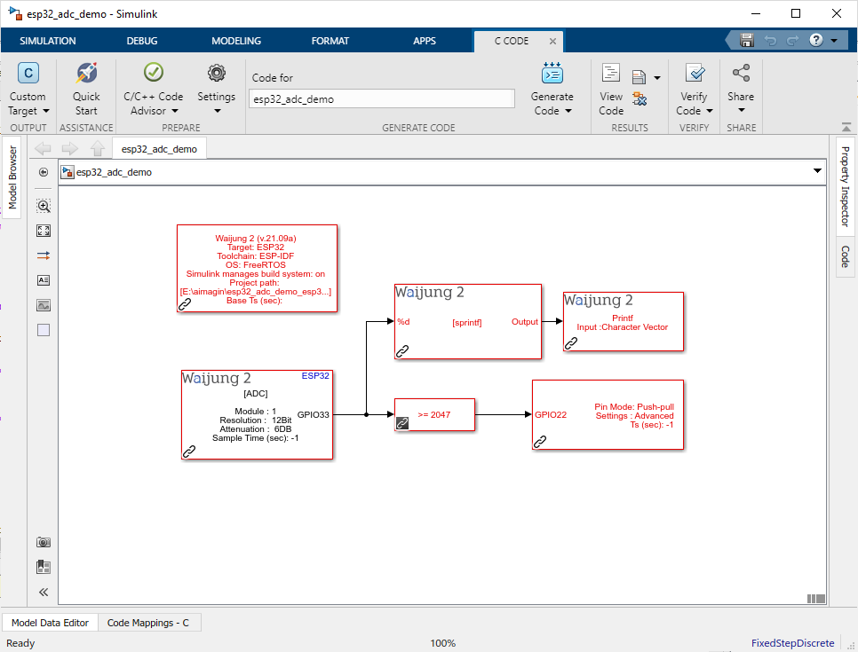
Description
This demo shows how to read ADC value and control a digital output pin according to the ADC value using ADC block and Digital output block. String_processing_block block and Print_block block is to monitor the ADC value from the serial port.
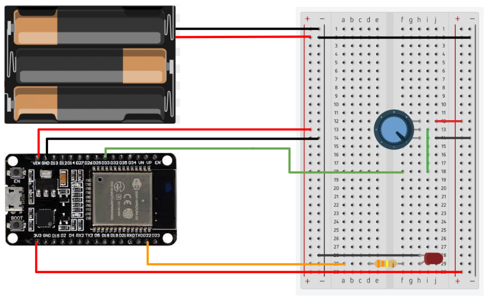
Hardware Setup
Connect the variable resistance output to the ADC pin(GPIO33) and connect the digital output pin (GPIO22) to a LED.
What should be happening?
When the input voltage to the ADC pin is below 1.65V the LED will OFF and if it is above 1.65V the LED will turn ON. From the Serial port user can also monitor the ADC value.
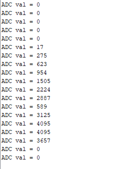
Serial monitor output: (Baud rate : 115200)