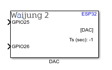
How this block appears in a Simulink model?
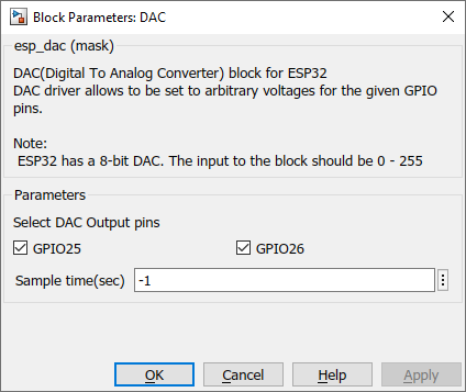
What can be configured?
Configuration Parameter |
Selectable Option/Value |
Description |
Select DAC output pins |
GPIO 25--GPIO 26 |
Select the output pin/pins |
Sample time (sec) |
-1 (inherited) or specify |
Specify sample time for the block |
INPUT/ OUTPUT Port
Port Name |
Port Type |
Date Type |
Description |
GPIOxx |
Scaler |
Double |
DAC value for the GPIO pin(it should be in a range of 0 - 255) |
When to use this block?
Use the Digital to Analog Convertor (DAC) Block to generate analog signals.
How does this block work?
The DAC block takes inputs as raw data (between 0 - 255) and generated output analog signals according to the following equation.
Analog output voltage = VREF x INPUT / 255
Limitations
Currently, this block is only support for ESP32 & ESP32S2 families. ESP32S3 & ESP32C3 does not have hardware built-in DAC.
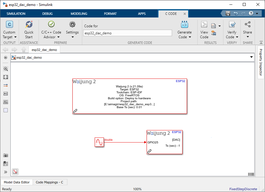
Demo
Demo file : esp32_dac_demo.slx
Description
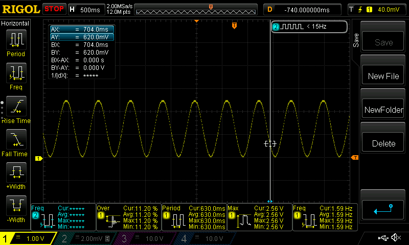
This demo shows how to use the DAC module with DAC_block . The DAC pin (GPIO25) generates a Sinusoidal Waveform with 0 - 2.56v with a frequency of 10 rad/sec.
Hardware Setup
Connect the DAC pin (GPIO25) to an oscilloscope to observe the wave form.
What should be happening?
The generated waveform should be as below