Introduction
This tutorial will be an extend version of tutorial 2 which will be using the video stream from the Pcam 5C camera instead of a still image. The image classification algorithm will be same as in tutorial 2 and the only difference is the input image source. This tutorial will first continue with the hardware designing in Vivado design suite and then it will focus on implementing the Simulink model.
Make the hardware design using Vivado
The hardware design for this tutorial will not be created from scratch. We are going to use the Pcam 5C demo from Digilent. We can use the same hardware design as in the demo and get the image frames to the PS in Zybo 7z20.
1.Download the Vivado design project Zybo-Z7-20-Pcam-5C-hw.zip and extract the zip file.
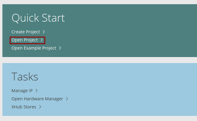
2.Open the Vivado design suite and go to Open Project
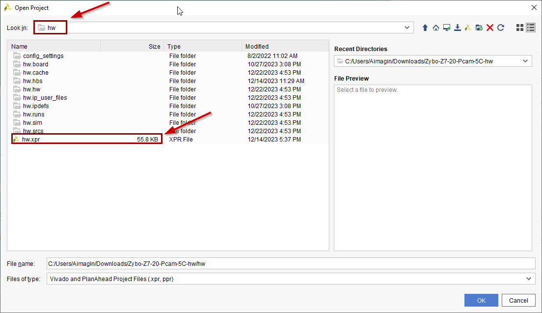
3.Browse to the hw folder inside the project folder that you downloaded and extracted and open the hw.xpr project file
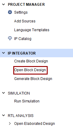
4.Once the project is opened successfully open the block design to see the existing block design
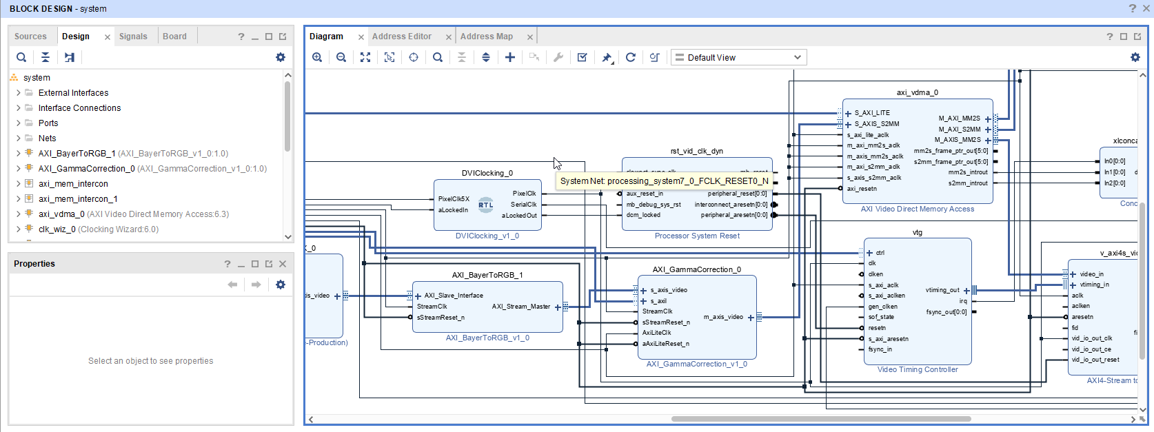
5.Following IPs are the main components of reading the camera, send the frame buffers to the PS and pass them to the HDMI TX
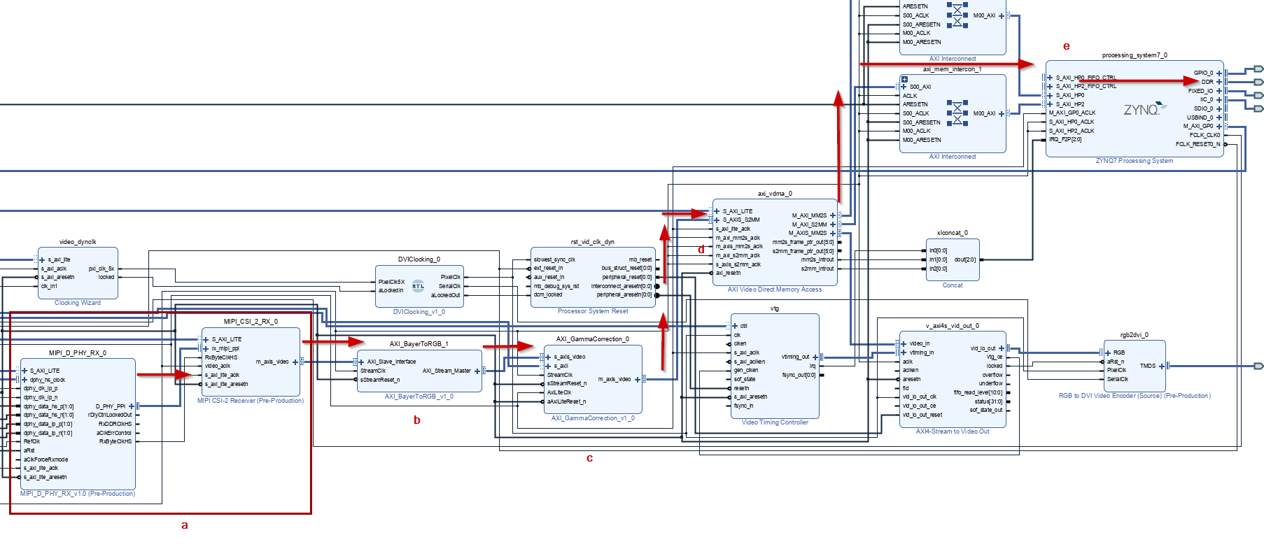
a.Reading Pcam 5C through the MIPI interface
b.Converting Bayer image buffer to RGB
c.Gamma correction
d.AXI VDMA which is used to read the AXI stream data (image buffer) and save it in the DDR memory through PS using AXI memory map
e.Access the image buffer in DDR and use it for further process in PS (eg. use as an input to the image classifier algorithm)
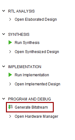
6.Next, generate the Bitstream by clicking on Generate Bitstream. Then click Yes to continue
7.Once the process is finished, click Cancel to the popup dialog box. Next, the remaining task is to export the hardware design file from Vivado. For that, go to File → Export → Export Hardware. Click Next on the wizard. Next, select Include Bitstream from the selection and click Next. Then give a proper name for the hardware design file and the location to export.
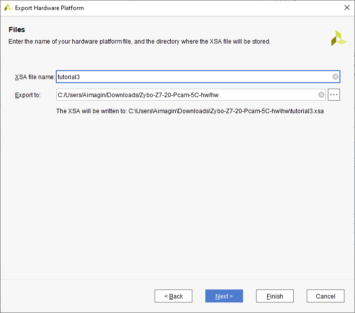
8.Then click on Next and click Finish
Create the Simulink Model
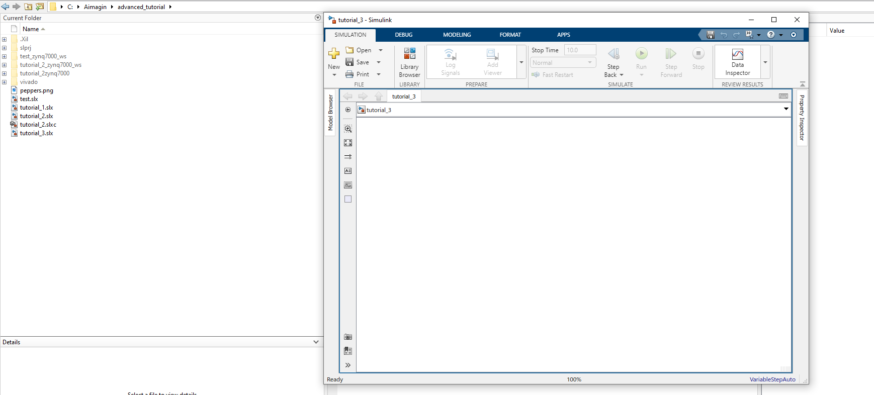
1.Open Matlab and change the current folder to the folder that you want to create the project. Then open Simulink, create a blank model and save it with a proper name
2.Import following blocks to the blank model
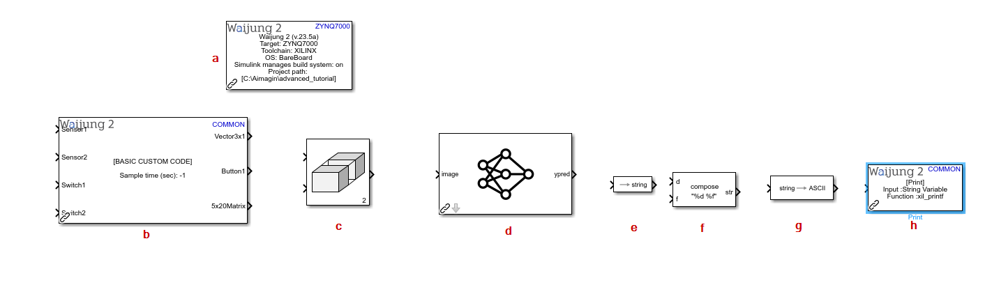
a.Waijung 2 Target Setup block
2.Modify following mask parameters of following blocks
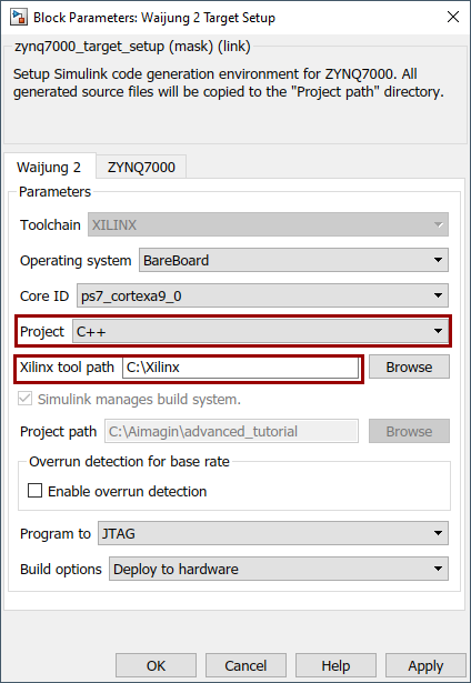
a.Waijung 2 Target Setup block
i.Waijung 2 tab
1.Project: C++
2.Xilinx tool path: Change the path according to your installed location of Xilinx tools
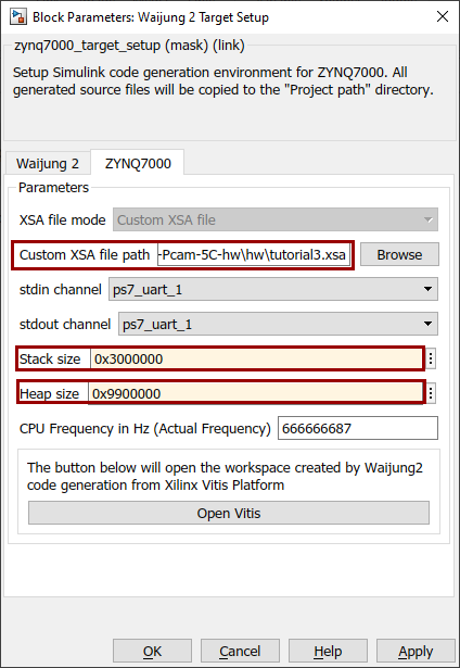
ii.ZYNQ7000 tab
1. Custom XSA file path: Location of the xsa file which you exported above using Vivado
2.Stack size: 0x3000000
3.Heap size: 0x9900000
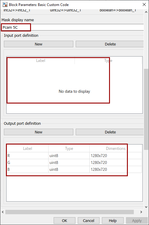
b.Basic Custom Code
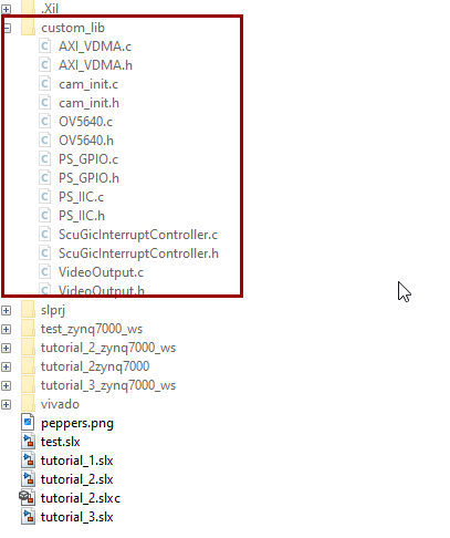
i.Download the C code library for camera and extract. Then copy it to the place where the Simulink mode is
ii.Mask display name: Pcam 5C
iii.Input port definition: Delete all
iv.Output port definition:
Label |
Type |
Dimentions |
R |
uint8 |
1280x720 |
G |
uint8 |
1280x720 |
B |
uint8 |
1280x720 |
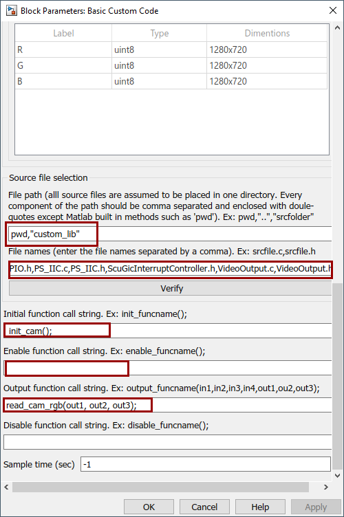
v.Source file selection
1.File path: pwd,"custom_lib"
2.File names: AXI_VDMA.c,AXI_VDMA.h,cam_init.c,cam_init.h,OV5640.c,OV5640.h,PS_GPIO.c,
PS_GPIO.h,PS_IIC.c,PS_IIC.h,ScuGicInterruptController.h,VideoOutput.c,VideoOutput.h
vi.Initial function call string: init_cam();
vii.Output function call string: read_cam_rgb(out1, out2, out3);
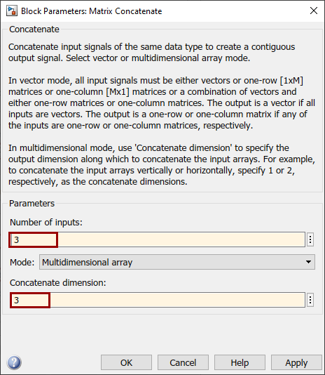
c.Matrix Concatenate
i.Number of inputs: 3
ii.Concatenate dimension: 3
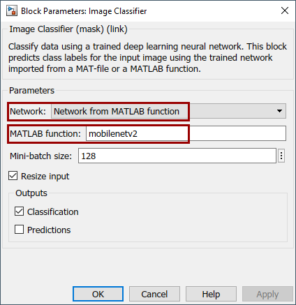
d.Image Classifier block
i.Network: Network from MATLAB function
ii.MATLAB function: mobilenetv2
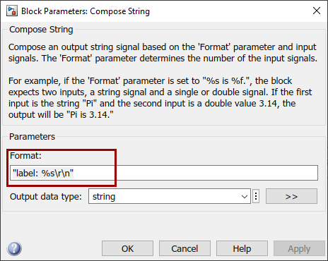
e.Compose String block
i.Format: "label: %s\r\n"
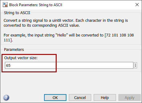
f.String to ASCII block
i.Output vector size: 64
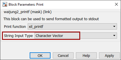
g.Print block
i.String Input Type: Character Vector
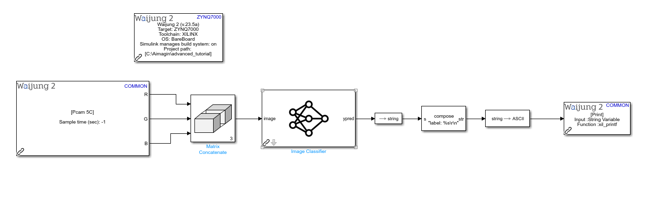
3.Connect each block as follows
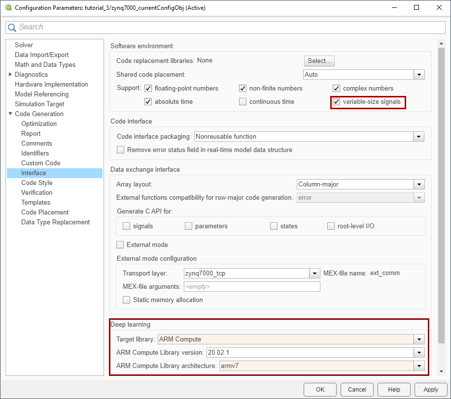
4.Change the following Model Configuration parameters (goto MODELING tab → Model Configuration parameters )which are related to the Image Classifier block
a.Code Generation → Interface → Deep learning
i.Target Library: ARM Compute
ii.ARM Compute Library version: 20.02.1
iii.ARM Compute Library architecture: armv7
b.Code Generation → Interface → Software environment
i.variable-size signals: Enable
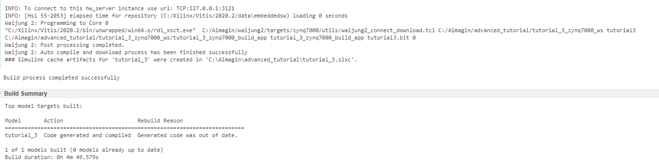
5.Save the Simulink model. Then go to APPS → Embedded Coder. To build the Simulink model go to C CODE → Build. Then connect the Zybo 7z20 board to the computer using the USB cable and connect the HDMI TX interface to a monitor. Turn on the board


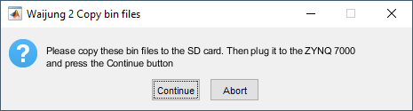
6.While the Simulink model is building, a dialog box will be popped up asking to copy the bin files from the opened folder to the SD card
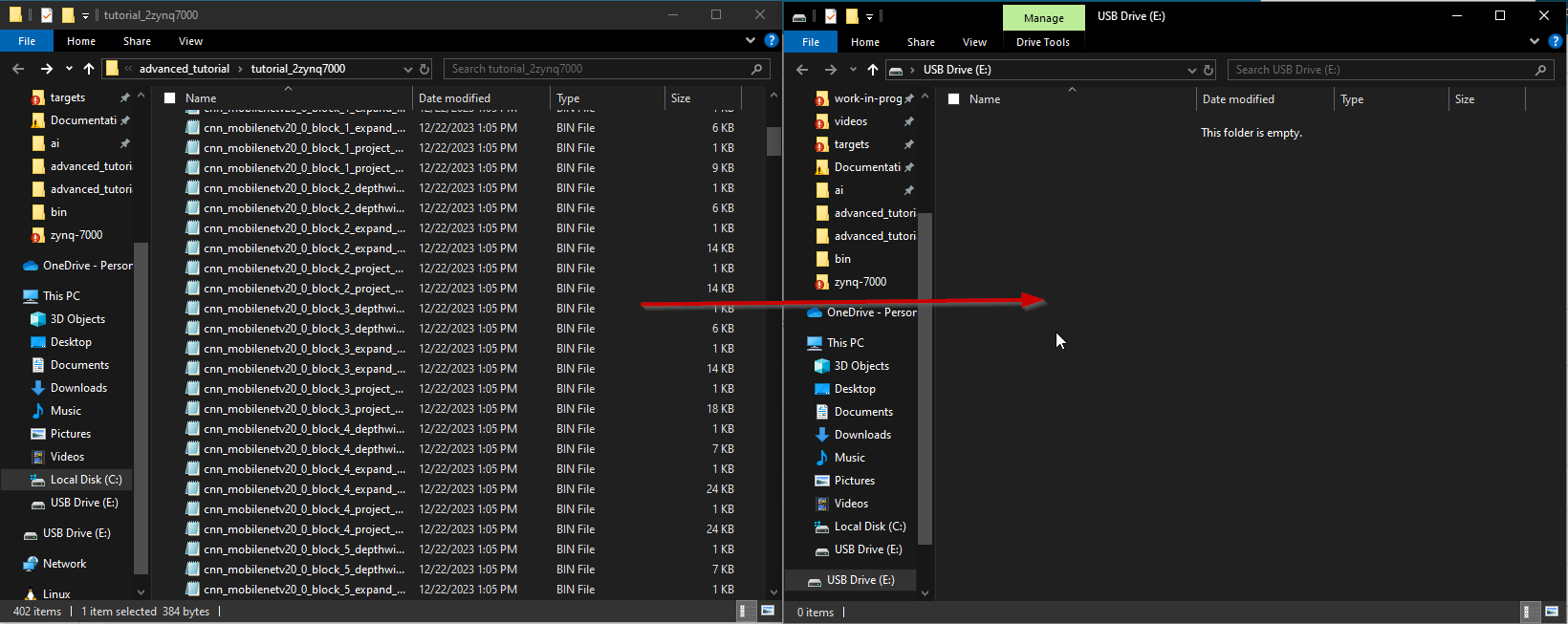
7.First, plug the micro SD card to the Computer and copy all the .bin files from the opened folder. A folder will be opened automatically when the above dialog box is popped up
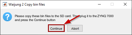
8.After all the .bin files are copied, plug the SD card to the Zybo 7z20 board and press Continue to the above dialog box so that it will continue the build process
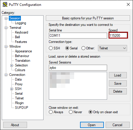
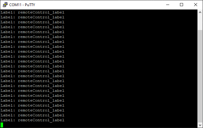
9.After the build process is successfully finished. Open the Serial Monitor with the correct COM port and set the Baudrate to 115200
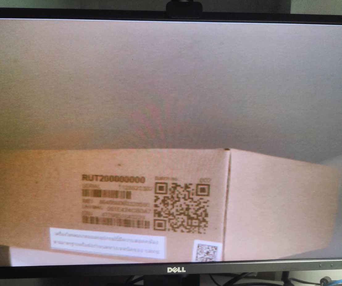
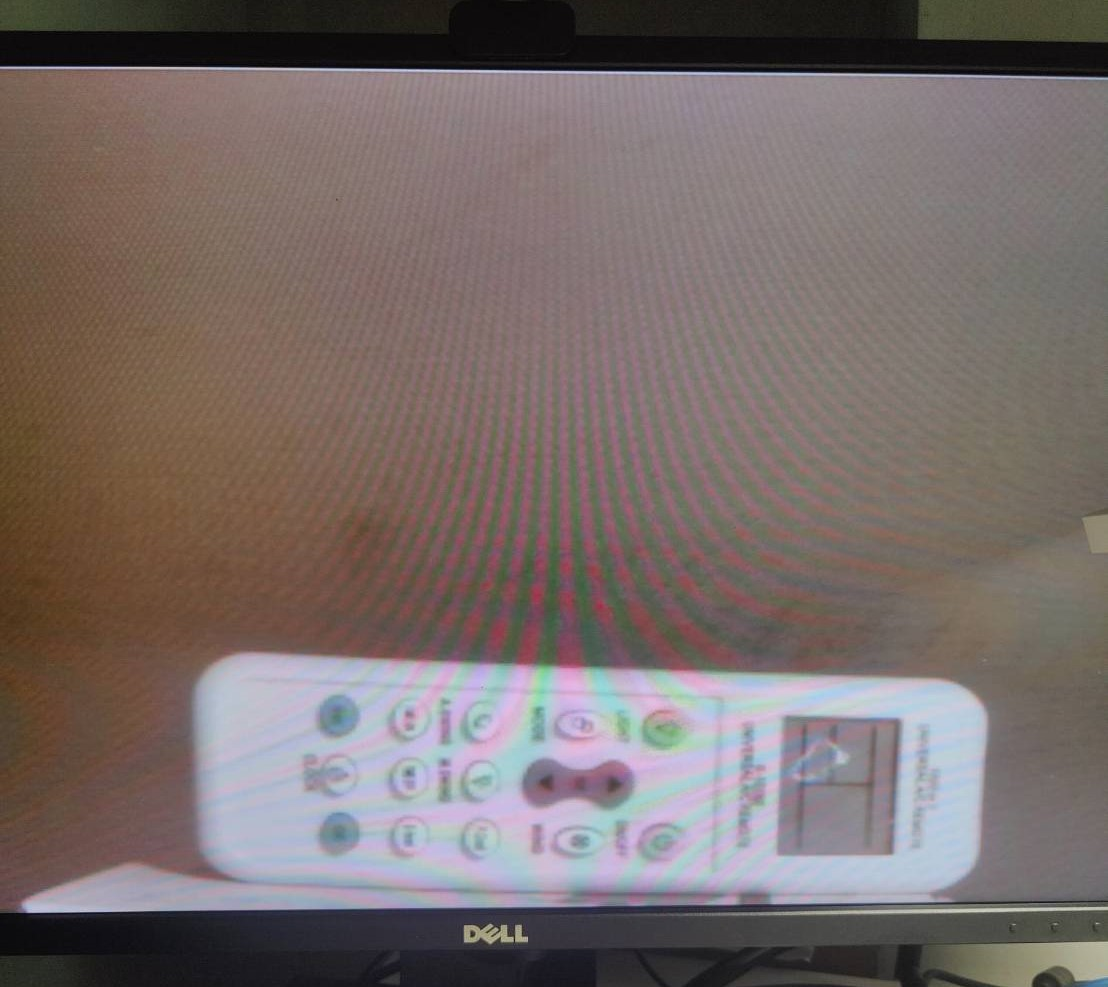
10.Point the camera to any object that you need to checkout. The most suitable label will printout in the serial monitor. Followings are the sample results.
a.Box
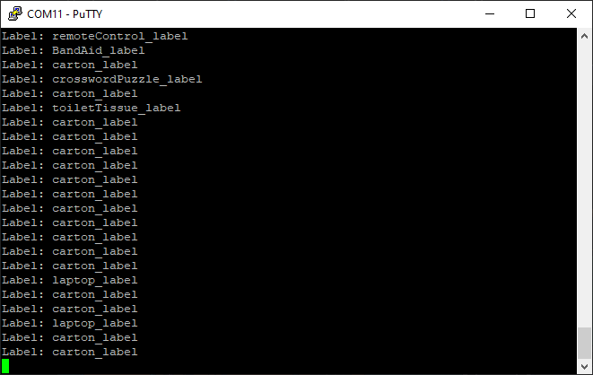
b.Remote controller
Resources
Simulink model: tutorial_3.slx
XSA file: tutorial3.xsa