Welcome! In this section, we’ll learn how to control the speed of Bala2 wheels using Waijung2. Let’s dive in!
Example Simulink Model: br_set_motor_speed.slx
Step 01: Add & Configure I2C Master Block
From the Waijung2 blockset, find the I2C Master block and add it to your model. This block will be used to initialize the IMU sensor.
Double-click on the I2C Master block to open its configuration parameters. Set Mode to Continuous. Set SDA pin - 21 and SCL pin - 22. Bytes write count should be set to 5, with first byte for the registry address (0x00).
Set the slave address to 0x3A.
The I2C Master block will write 4 bytes of data to control speed. The first 2 bytes correspond to the left wheel speed, and the last 2 bytes correspond to the right wheel speed.

Figure 87: Add I2C Master Block

Figure 88: Configure I2C Master block
Step 02: Convert Speed to int8
Convert the speed to int8 using a data type converter block.

Figure 89: Convert to int8
Step 03: Bit Shift
Perform a bit shift on the second and fourth bytes by 8 to the left using a shift arithmetic block in Simulink.

Figure 90: Bit Shift
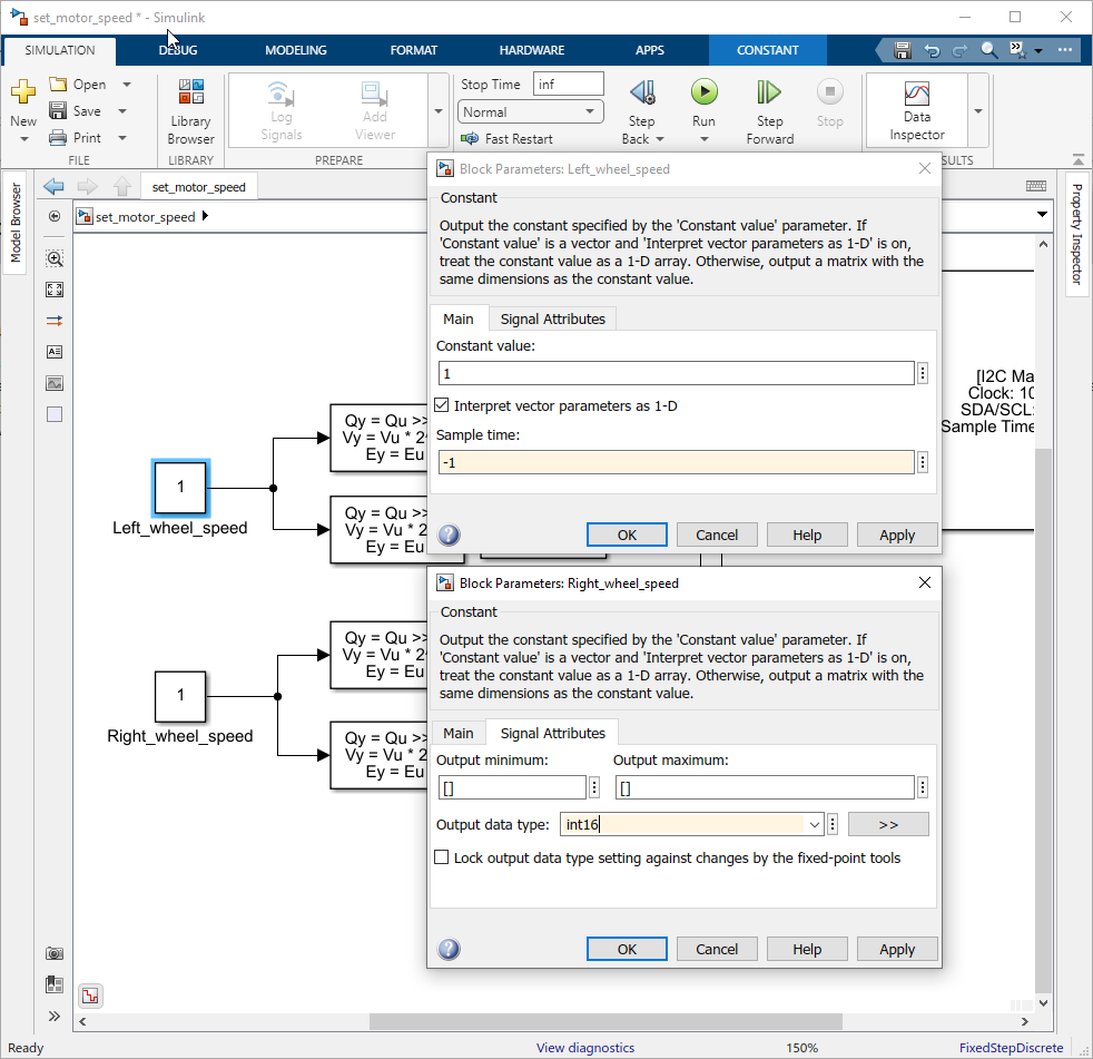
Step 04: Add & Configure I2C Master Block
Create two constant blocks with the sample time set to -1 and the data type set to int16. Connect the first constant block to the first and second shift arithmetic blocks and second constant block to third and fourth shift arithmetic blocks.
Step 05: Create a Subsystem
Select blocks used for the set speed and right-click and select Create Subsystem from the drop down menu.

Figure 91: Create Subsystem
Step 06: Add knobs to control constant block value
Finally, add two knobs to control the value of the constant blocks.

Figure 92: Add and Configure Knob block

Figure 93: After configuring the two knobs
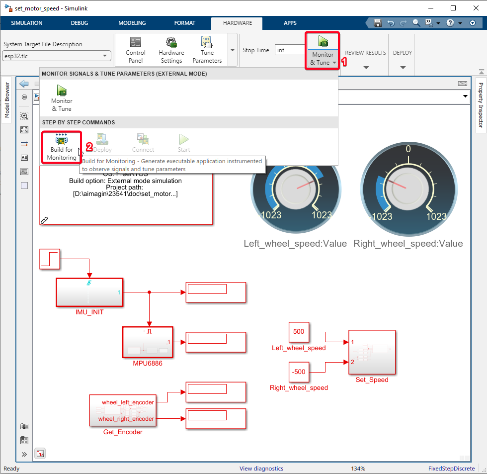
Step 07: Build Simulink Model
Click on the Hardware Tab. Select the Drop down of "Monitor & Tune" and select "Build for Monitoring".
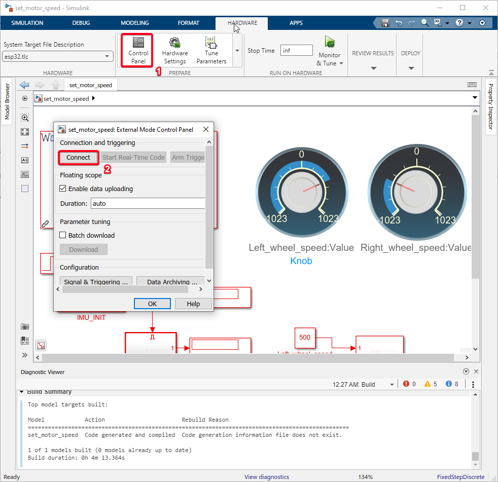
Step 08: Run External mode Simulation
Click on the Control Panel and click on the 'Connect' button.
Step 09: Verify Results
After running the external mode simulation, you can verify the results by observing the Bala2 wheels while turning the knob.
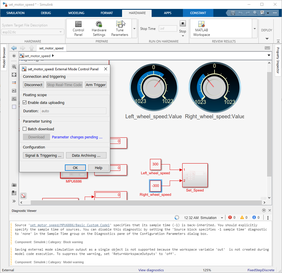
Upon completion of these steps, you should be able to successfully control the speed of the Bala2 wheels using Waijung2. The knobs should allow for real-time adjustments of the wheel speeds, and you should observe corresponding changes in the Bala2 wheels’ movements. This confirms that the setup is working as expected.
Example Simulink Model: br_set_motor_speed.slx