In this section, we will develop a Simulink model to read Inertia Measurement Unit (IMU) sensor data and calculate the tilt (roll) angle using Waijung2 custom code. This involves the following steps:
1.Introduction to IMU Sensors:
An Inertial Measurement Unit (IMU) is a device that measures and reports force, angular rate, and sometimes orientation.The M5Stack Bala2 uses the MPU-6886 IMU sensor, which is a 6-axis sensor combining a 3-axis gyroscope and a 3-axis accelerometer. It communicates with the host computer via an I2C interface and has a 16-bit ADC along with a built-in programmable digital filter. This allows the sensor to calculate tilt angle and acceleration in real-time, making it ideal for a self-balancing robot.
References : 6-Axis IMU Unit MPU-6886
Example Simulink model:br_imu_read.slx
2.Building the Simulink Model:
This section will be a step-by-step guide on how to build a Simulink model for reading the IMU sensor data. It will include the following steps:
2.1. Initializing the IMU Sensor:
Here’s how you can initialize the IMU sensor in Simulink using Waijung2:
Step 01: Start Simulink
Open MATLAB and start Simulink. Create a new model.

Figure 66: Create new Simulink model
Step 02: Add Waijung 2 Target Setup Block
From the Waijung2 blockset, find the Target setup block and add it to your model.

Figure 67: Add Waijung 2 Target Setup block to the model
Step 03: Configure Target Setup Block
Double-click on the Target setup block to open its configuration parameters. Set the build option to ‘External Mode Simulation’. This mode allows you to run real-time simulations, which will be handy in later steps when reading the robot tilt angle.

Figure 68: Select External mode simulation as Build Option
Select FreeRTOS tab and change "Default xTaskCreate_stack depth" to 20480.

Figure 69: Increase Default xTaskCreate_stack depth to 20480
Select ESP32 tab and Select the COM port connected to M5Stack BALA2 FIRE.

Figure 70: Select ESP32 COM port
Select Host-board connection tab. Select "TCP/IP" as Communication Interface. Select "WIFI AP" as WiFi mode. Set wifi ssid and password.

Figure 71: Configure Host-board connection with WIFI AP mode
Step 04: Save and Update the Model: After configuring the Target setup block, save and update your model to apply the changes.

Figure 72: Save and Update Simulink Model
Step 05: Add I2C Master Block
From the Waijung2 blockset, find the I2C Master block and add it to your model. This block will be used to initialize the IMU sensor.

Figure 73: Add Waijung 2 I2C Master block
Step 06: Configure I2C Master Block
Double-click on the I2C Master block to open its configuration parameters. Set Mode to Continuous. Set SDA pin - 21 and SCL pin - 22. Bytes write count should be set to two, with one byte for the registry address and the other for the value to be written to that address.

Figure 74: Configure I2C Master block
Set the slave address to the address of your IMU sensor. Set Registry Address and value as follow.

Figure 75: Set Slave Address, Register Address & Value to the I2C block
Step 07: Add a block for each initialization, enter the registry address and value, and include a delay using vTask delay
Register Name |
Register Address (HEX) |
Register Value (HEX) |
Description |
Delay (ms) |
|---|---|---|---|---|
PWR_MGMT_1 |
0x6B |
0x00 |
Sets the device to its default operating mode |
10 |
PWR_MGMT_1 |
0x6B |
0x80 |
Reset the internal registers and restores the default settings. |
10 |
PWR_MGMT_1 |
0x6B |
0x01 |
The device auto-selects the best available clock source. It will use the Phase-Locked Loop (PLL) if it’s ready; otherwise, it will use the internal oscillator. |
10 |
ACCEL_CONFIG |
0x1C |
0x10 |
Set the accelerometer sensitivity to ±8g |
1 |
GYRO_CONFIG |
0x1B |
0x18 |
Set the gyroscope sensitivity to ±2000 dps |
1 |
CONFIG |
0x1A |
0x01 |
Set the Digital Low Pass Filter (DLPF) configuration |
1 |
SMPLRT_DIV |
0x19 |
0x01 |
Set the sample rate divider |
1 |
INT_ENABLE |
0x38 |
0x00 |
Disable the interrupt |
1 |
ACCEL_CONFIG2 |
0x1D |
0x00 |
Set the accelerometer configuration 2 |
1 |
USER_CTRL |
0x6A |
0x00 |
Set the user control |
1 |
FIFO_EN |
0x23 |
0x00 |
Disable the FIFO |
1 |
INT_PIN_CFG |
0x37 |
0x22 |
Set the interrupt pin configuration |
1 |
INT_ENABLE |
0x38 |
0x01 |
Enable the interrupt |
10 |
GYRO_CONFIG |
0x1B |
0x18 |
Set the gyroscope sensitivity to ±2000 dps |
10 |
ACCEL_CONFIG |
0x1C |
0x10 |
Set the accelerometer sensitivity to ±8g |
10 |
To initialize the IMU, you should use the register addresses, values, and delays provided in the table above. For each command, you will need to create an I2C block that includes the specific register address and value. Immediately following each I2C block, you should include a vTask delay block with the specified delay. This process ensures that each command is properly executed and that the IMU has sufficient time to respond before the next command is sent. Remember, each command requires one I2C block and a subsequent vTask delay block for successful initialization.
Step 08: Monitor the Initialization Status
After setting up the I2C blocks and vTask delay blocks for each initialization command, connect the output of each I2C block to an AND block. Then, use a comparison block to check whether all output values are equal to 0. A value of 0 from all I2C blocks indicates that the initialization process has been successful. If there is an error during initialization, the output value will be -1. This step allows you to effectively monitor and verify the status of the IMU initialization process.

Figure 75: Monitor the initialization Status
Step 09: Create a Trigger Subsystem
This step is to create a trigger subsystem that includes all the I2C blocks and the vTask delay blocks, and outputs the status comparison. Use a step block to run the subsystem only once at the start of the process using a trigger. This setup ensures that the initialization process is executed correctly and allows you to monitor its status effectively.

Figure 76: Create a trigger Subsystem
Step 10: Build Simulink Model
Click on the Hardware Tab. Select the Drop down of "Monitor & Tune" and select "Build for Monitoring"

Figure 77: Build Simulink model
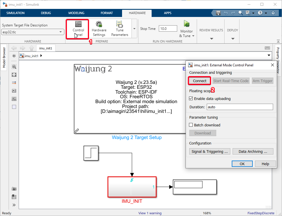
Step 11: Run External mode Simulation
Click on the Control Panel and click on the 'Connect' button
Step 12: Results Verification
After initialization, adding a Display block and connecting it to the output of the trigger subsystem, which is linked to the output of the comparison block, allows for effective monitoring. Running the model and checking for a ‘1’ on the Display block confirms successful initialization with no errors. This is a crucial step for early issue detection.

Figure 78: Results Verification
Example Simulink model: br_imu_init.slx
2.2. Accessing IMU Sensor Data:
The Inertial Measurement Unit (IMU) sensor data from the M5Stack Bala2 is accessed using the I2C (Inter-Integrated Circuit) protocol. The I2C_Read_NBytes and I2C_Write_NBytes functions are used to read and write data to the IMU.
Instead of reading data directly from the accelerometer and gyroscope registers, the data is stored in a FIFO (First In, First Out) buffer in the IMU. This method is chosen for several reasons:
•Data Loss Prevention: If the microcontroller is busy with other tasks and doesn’t read the data from the IMU registers in time, the new data can overwrite the old data, resulting in data loss. The FIFO buffer stores multiple data samples, so even if the microcontroller is temporarily unable to read the data, the data won’t be lost.
•Efficiency: Reading data from the FIFO buffer can be more efficient than reading individual register values. The microcontroller can read multiple data samples from the buffer at once, reducing the overhead of initiating a read operation for each sample.
•Synchronization: The FIFO buffer ensures that the accelerometer and gyroscope readings are synchronized. When you read the data from the buffer, you get a set of accelerometer and gyroscope readings that were taken at the same time. If you read the registers individually, there could be a delay between reading the accelerometer and gyroscope registers, leading to unsynchronized data.
In some cases, the standard blocks provided by Waijung 2 may not be sufficient to implement the desired functionality. This is where the custom code block comes in handy. The custom code block allows you to write your own C code that gets integrated into the generated code from the Waijung 2 model. In the case of the Bala2 balancing robot, the number of bytes to read from the IMU’s FIFO buffer can change dynamically during runtime. However, the standard Waijung 2 I2C Master blocks require the number of bytes to read/write to be set in advance and don’t allow it to be changed during runtime. To overcome this limitation, a custom code block was used to implement the logic for reading data from the IMU. The custom code dynamically calculates the FIFO count (the number of bytes available to read from the FIFO buffer) and then reads that many bytes from the buffer. This wouldn’t be possible with the standard I2C Master block, hence the need for a custom code block.
Step 01: Include Custom code to model path
Extract the “imumpu6886.zip” file to obtain the “imumpu6886” folder. This folder contains the “imumpu6886.c” and “imumpu6886.h” custom code files, which were created using the M5Stack BALA2 Fire example.

Figure 79: Extract the imumpu6886 folder

Figure 80: Custom code C and H File
Step 02: Add Basic Custom Code Block
From the Waijung2 blockset, find the Basic Custom Code block and add it to your model. This block will be used to access data from the IMU sensor.

Figure 81: Add Basic Custom Code block
Step 03: Configure Basic Custom Code
Double-click on the Basic Custom Code block to open its configuration parameters.Adjust the parameters according to the provided figure.

Figure 82: Config Basic Custom Code block
Step 03: Verify Custom Code files
Double-click on the Basic Custom Code block to open its configuration parameters.Click on the 'Verify' button.

Figure 83: Verify Custom Code files
2.3. Applying the Butterworth Filter:
In the custom code, the Butterworth filter is applied to the accelerometer readings to reduce high-frequency noise and smooth the data. This is done in the 'ImuUpdateTask' function, where the raw accelerometer readings are passed through the Butterworth filter before being used in the Madgwick AHRS algorithm. The Butterworth filter parameters (coefficients a1, a2, b0, b1, b2) are set to create a low-pass filter with a cutoff frequency of 50Hz, which is suitable for smoothing accelerometer data sampled at 500Hz.This filter was implemented using the example of BALA2 provided by M5Stack. You can find the original implementation on the M5Stack GitHub repository.
2.4. Applying the MadgwickAHRS Filter:
The MadgwickAHRS filter, implemented in the custom code, is an orientation filter widely used in motion tracking and pose estimation. It’s designed to fuse data from multiple sensors such as accelerometers and gyroscopes. The filter uses this data to estimate the orientation of the object the sensors are attached to, in terms of roll, pitch, and yaw.The roll angle (roll_ahrs) is one of the outputs of this function.This filter was implemented using the example of BALA2 provided by M5Stack. You can find the original implementation on the M5Stack GitHub repository.
2.5. Calculating the Roll Angle:
The roll angle can be calculated from the output of the Madgwick filter, which is typically a quaternion.
The quaternion can be converted to Euler angles (including the roll angle) using the following formula:
where q0, q1, q2, and q3 are the components of the quaternion.
Accelerometer-based roll angle
The fast_to_normal_angle flag is used to check if the estimated roll angle has converged to the correct value. Initially, the MadgwickAHRSetBeta function is called with a high beta value (10) to make the filter converge quickly. This is the “fast” mode. Once the estimated roll angle is within 1 degree of the accelerometer-based roll angle, the fast_to_normal_angle flag is set to false, and the beta value is reduced (to 0.1) to make the filter more accurate but slower to converge. This is the “normal” mode.If the filter is in “normal” mode (fast_to_normal_angle is false), the global angle variable is updated with the estimated roll angle (roll_ahrs). This angle is then used by the robot’s control system to maintain balance.
3.Understanding and Testing the IMU Sensor Data:
The Inertial Measurement Unit (IMU) sensor provides crucial data for controlling the balance of the robot.

Figure 84: Simulink Model for reading IMU
To test the Simulink model and ensure it’s correctly reading the IMU sensor data, you can follow these steps:
Step 01: Build Simulink Model
Click on the Hardware Tab. Select the Drop down of "Monitor & Tune" and select "Build for Monitoring"

Figure 84: Build Simulink Model
Step 02: Run External mode Simulation
Click on the Control Panel and click on the 'Connect' button

Figure 85: Run External mode
Step 03: Verify Results
After running the external mode simulation, you can verify the results by observing the roll angle readings from the IMU sensor.
•When the robot is standing straight without the wheel, the IMU reading for the roll angle should be approximately 1.228 degrees. This indicates that the robot is almost upright.
•When the robot is turned 90 degrees counter-clockwise, the roll angle should be approximately -84.99 degrees. The negative sign indicates a counter-clockwise rotation.
•When the robot is turned 90 degrees clockwise, the roll angle should be approximately 86.1 degrees. A positive angle indicates a clockwise rotation.

Figure 86: Result Verification when -90

Figure 86: Result Verification when 0

Figure 86: Result Verification when +90
In conclusion, the results indicate that the Simulink model is successfully interfacing with the IMU sensor and accurately estimating the robot’s orientation. The roll angle readings from the IMU sensor closely match the physical orientation of the robot in various positions. This demonstrates the effectiveness of the IMU sensor data processing, including the application of the Butterworth and MadgwickAHRS filters. It’s a testament to the robustness of the system built.
Example Simulink model: br_imu_read.slxbr_imu_read.slx