In this section of the tutorial, we’ll be focusing on how to read wheel speed using encoder data. This is a crucial step in controlling the movement of your self-balancing robot and involves two main parts:
1.Encoder Reading
2.Implementation of Motor Speed Filter
By the end of this section, you’ll have a deeper understanding of how encoder data can be used to accurately control the speed of the robot’s wheels. This knowledge will be invaluable as you proceed to the next stages of implementing the PID controller and developing the balancing algorithm. Let’s dive in!
Example Simulink Model: br_motor_speed_filter.slx
Encoder Reading
The first part involves reading encoder data using Waijung2. Encoders provide information about the position of the wheels, which is essential for controlling the robot’s movements.
Step 01: Add & Configure I2C Master Block
From the Waijung2 blockset, find the I2C Master block and add it to your model. This block will be used to initialize the IMU sensor.
Double-click on the I2C Master block to open its configuration parameters. Set Mode to Continuous. Set SDA pin - 21 and SCL pin - 22. Bytes write count should be set to one, with one byte for the registry address (0x10). Bytes read count should be 8.
Set the slave address to 0x3A.
The I2C Master block will read 8 bytes of data from the encoder. The first 4 bytes correspond to the left wheel encoder data, and the last 4 bytes correspond to the right wheel encoder data.
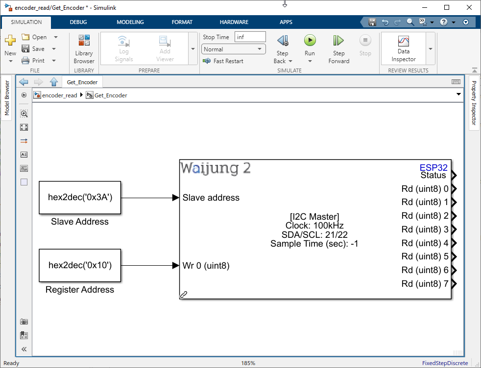
Figure 94: Add I2C Master block
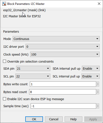
Figure 95: Configure I2C Master block
Step 02: Convert Data Type
The output from the I2C Master block is of type uint8. However, for the bitwise operations, we need to work with int32 data type. Therefore, the first step is to change the data type from uint8 to int32. You can do this using the Data Type Conversion block in Simulink.
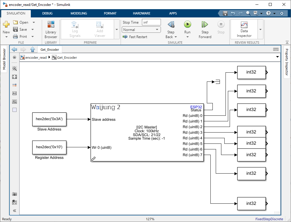
Figure 96: Conver Data Type
Step 03: Shift Bytes for Left Wheel Encoder Data
For the left wheel encoder data, shift the first byte to the left by 24 bits, the second byte to the left by 16 bits, and the third byte to the right by 8 bits. The fourth byte will remain the same.
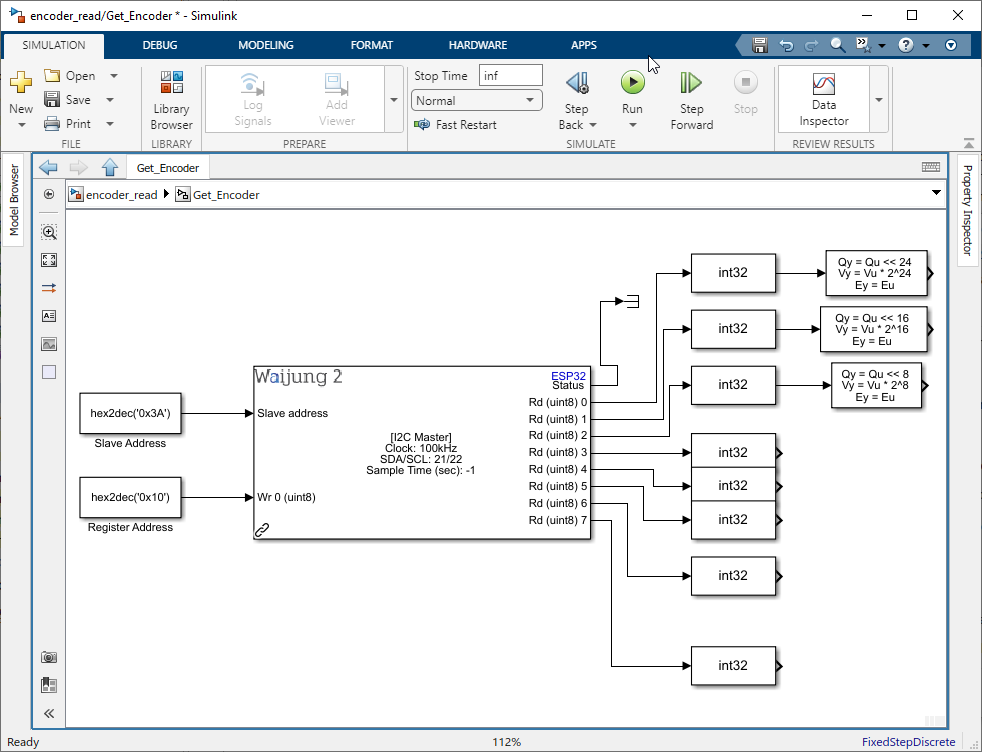
Figure 97: Shift Bytes for Left Wheel Encoder Data
Step 04: Combine Bytes for Left Wheel Encoder Data
After shifting the bytes, use the Bitwise Operator (OR) block to combine them into a single 32-bit integer. This gives you the encoder value for the left wheel.
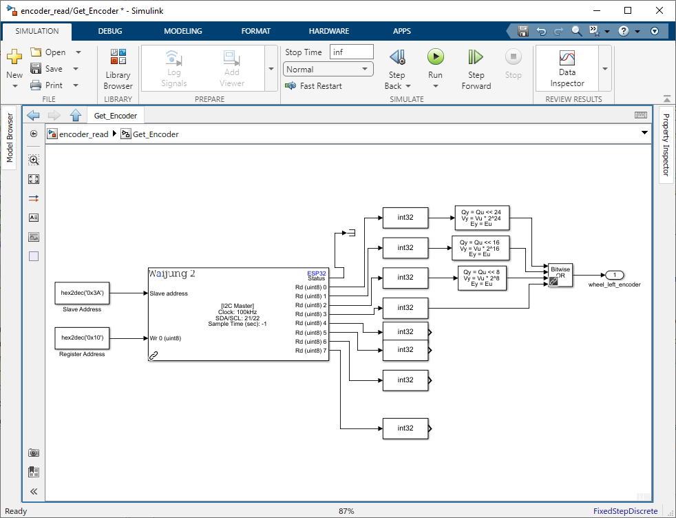
Figure 98: Combine Bytes for Left Wheel Encoder Data
Step 05: Shift Bytes for Right Wheel Encoder Data
Repeat the same process with the next 4 bytes for the right wheel encoder data.
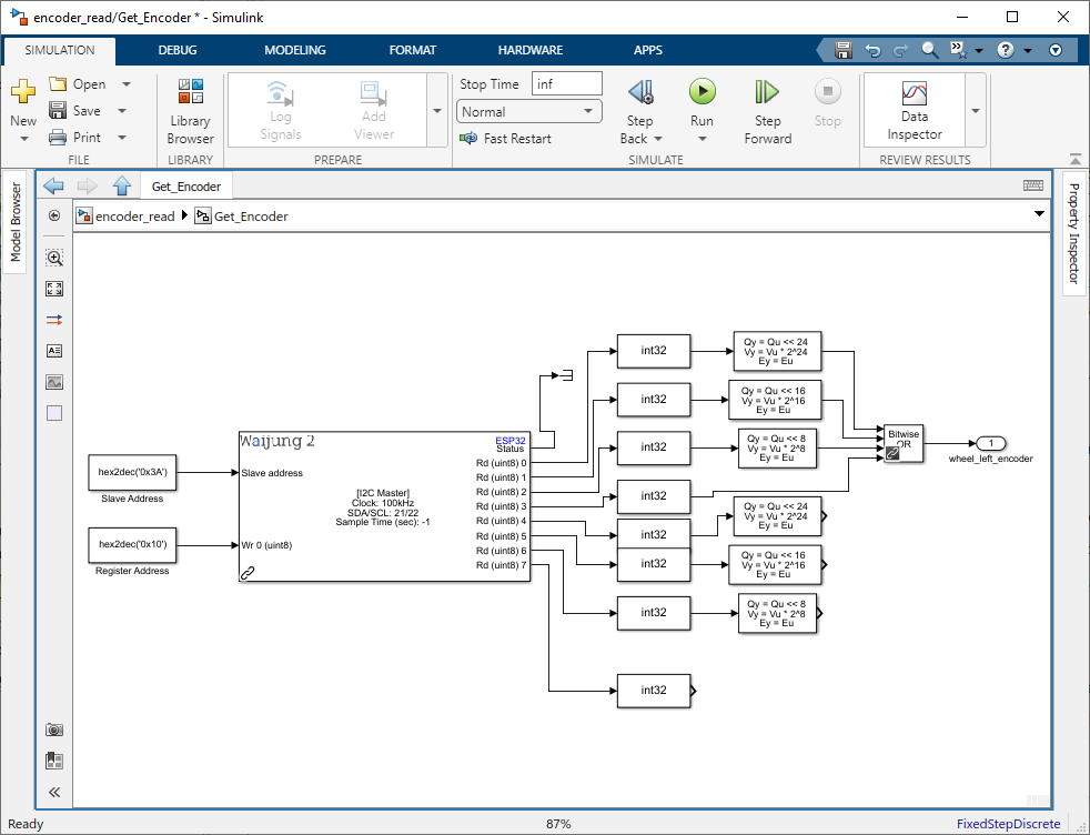
Figure 99: Shift Bytes for Right Wheel Encoder Data
Step 06: Combine Bytes for Right Wheel Encoder Data
Again, use the Bitwise Operator (OR) block to combine the shifted bytes into a single 32-bit integer. This gives you the encoder value for the right wheel.
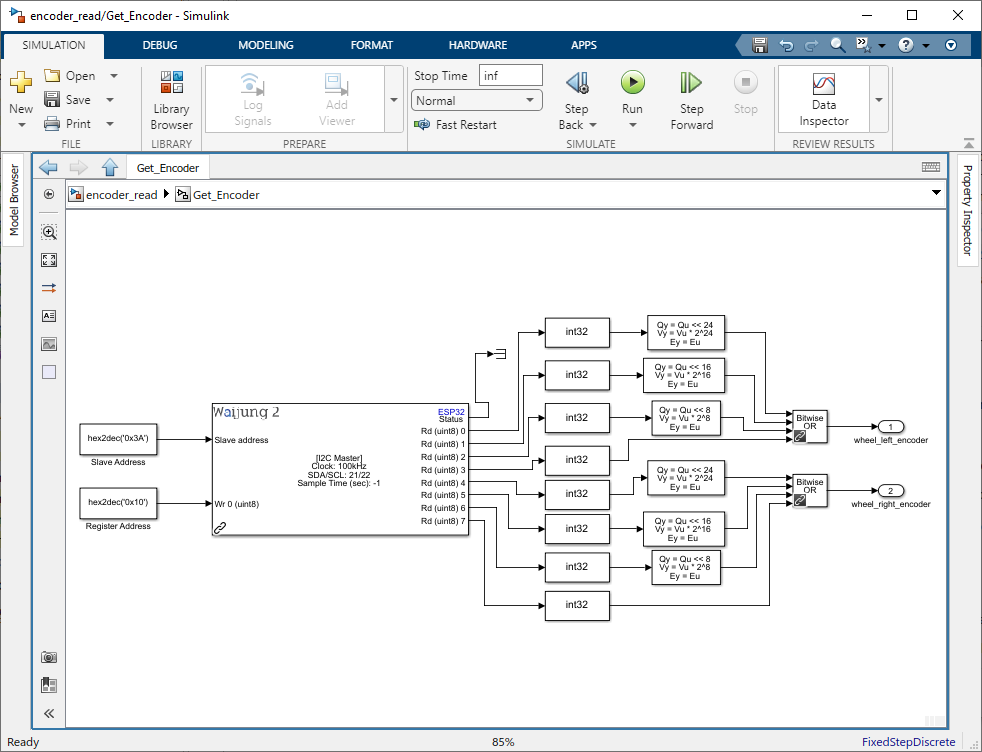
Figure 100: Combine Bytes for Right Wheel Encoder Data
Step 07: Create Subsystem and Connect to Output
Select blocks used for the encoder reading and right-click and select Create Subsystem from the drop down. Then connect the output of the subsystem to Display blocks.
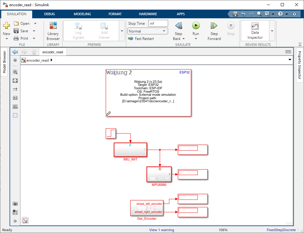
Figure 101: Create Subsystem and Connect to Output
Step 08: Build Simulink Model
Click on the Hardware Tab. Select the Drop down of "Monitor & Tune" and select "Build for Monitoring".
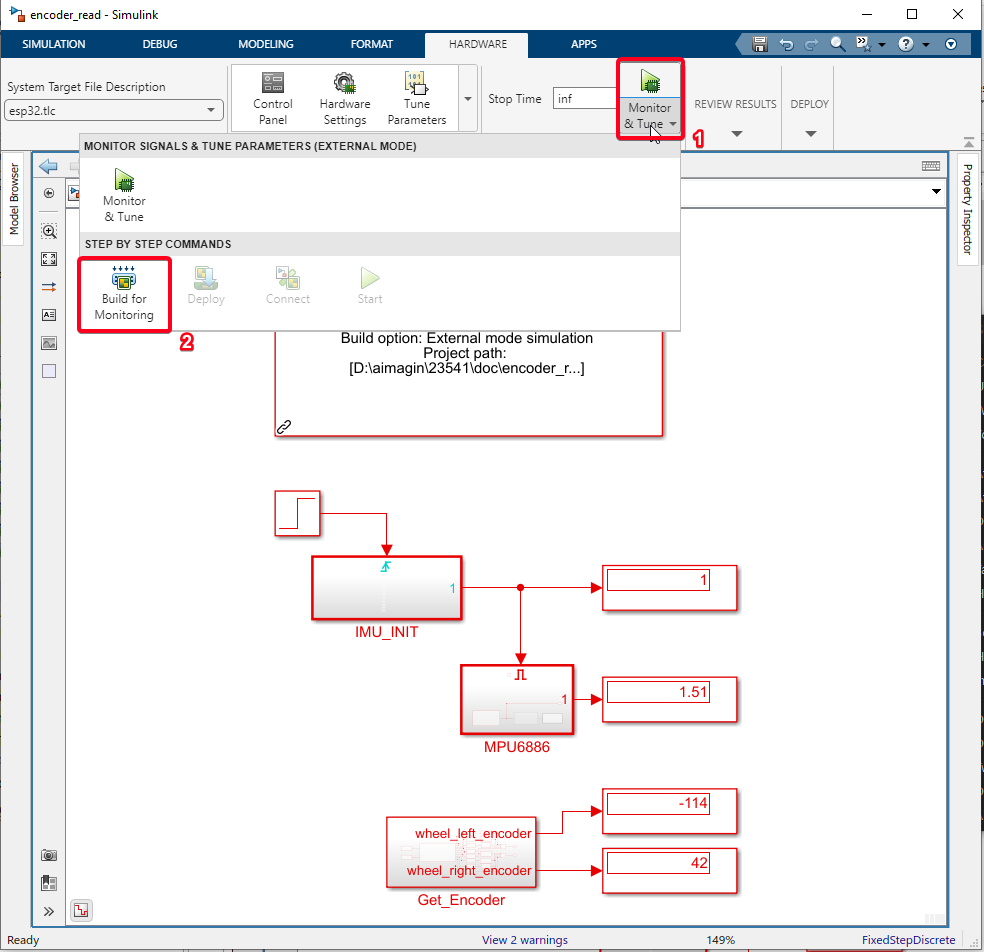
Figure 102: Build Simulink Model
Step 09: Run External mode Simulation
Click on the Control Panel and click on the 'Connect' button.
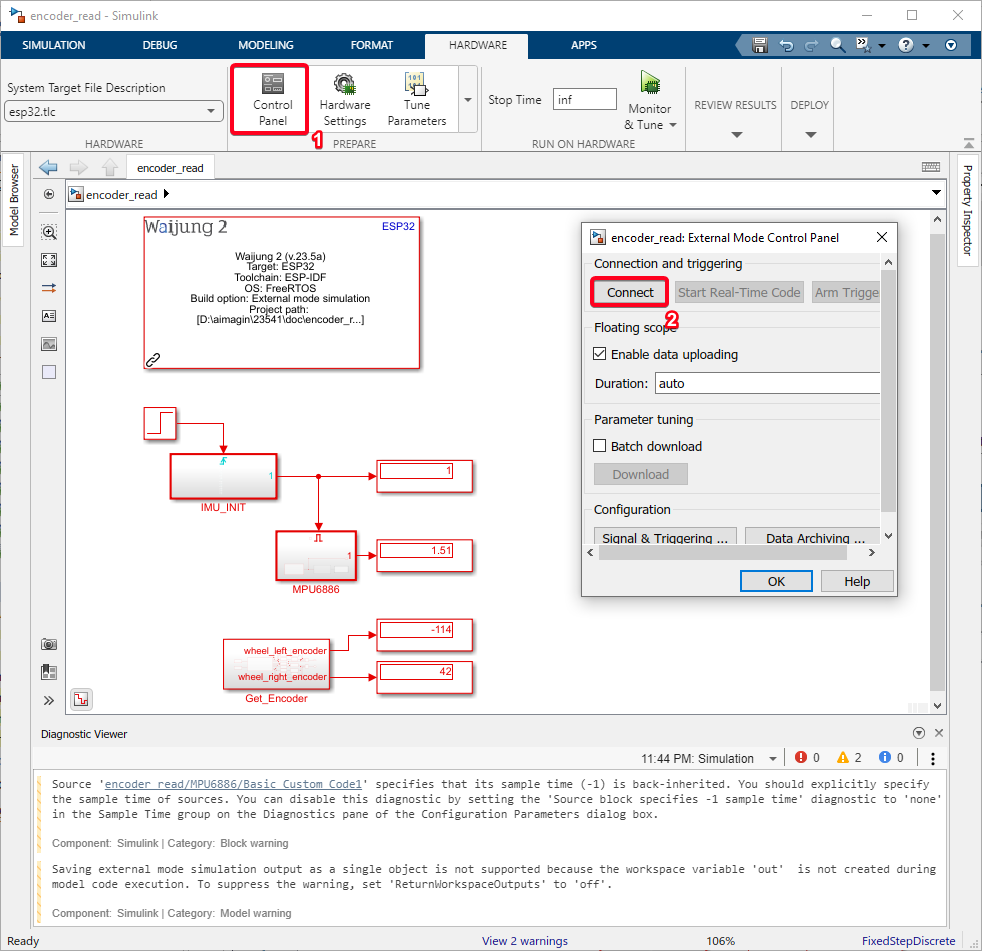
Figure 102: Run External mode Simulation
Step 10: Verify Results
After running the external mode simulation, you can verify the results by observing the encoder readings while turning the wheels .
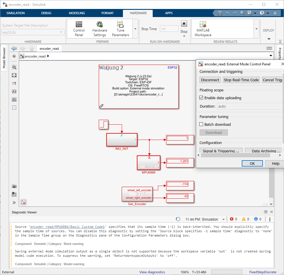
Figure 103: Verify Results
After completing these steps, you should be able to accurately read the encoder data. Now that you’ve acquired the encoder data, it’s time to put that data to use. In the next section, we’ll use the encoder data to calculate the wheel speed.
Example Simulink Model: br_encoder_read.slx
Implementation of Motor Speed Filter
Once we have the encoder data, we’ll move on to the second part, which involves implementing a motor speed filter in Simulink using blocks.
The filter uses the equation,
to smooth out the fluctuations in the motor speed readings, providing a more accurate and stable measurement for controlling the robot’s movements.
Step 01: Add "Add" block to get encoder value
Add "Add" block and connect the wheel left encoder value and wheel right encoder value to sum them.
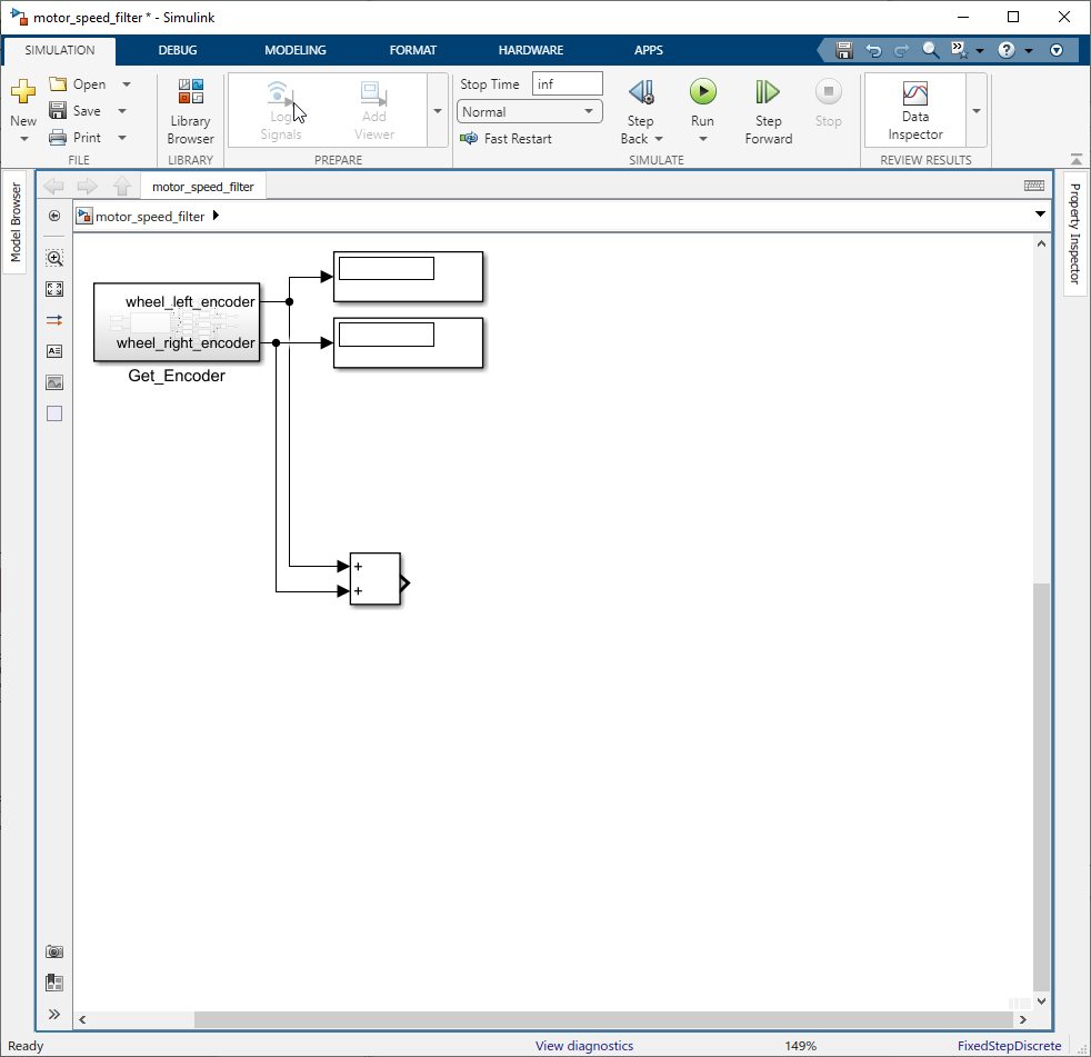
Figure 104: Add "Add" block and sum encode
Step 02: Add "Data Store Memory" block and Configure
Add "Data Store Memory" block. Double-click on the Data Store Memory block to open its configuration parameters. Set Data store name to "encoder" and change Data type to int32 in the Signal Attribute tab.
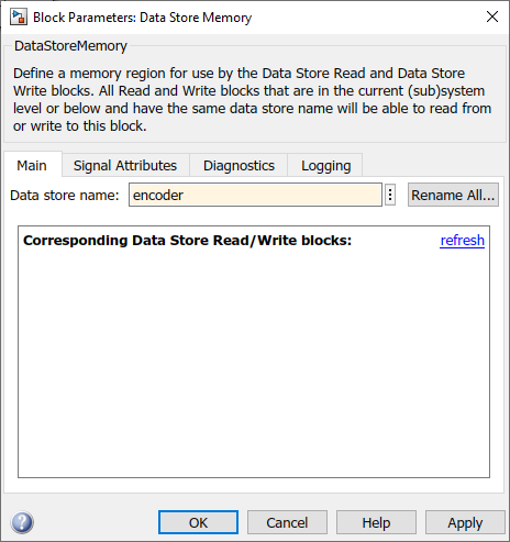
Figure 105: Add Data Store Memory block
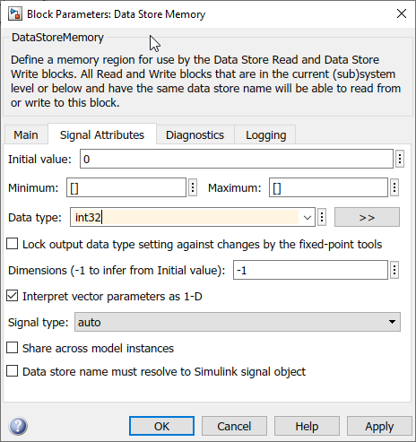
Figure 106: Configure Data Store Memory block
Step 03: Add "Data Store Write" block and Configure
Add "Data Store Write" block and connect it to the output of the "Add" block. Double-click on the Data Store Write block to open its configuration parameters. Select Data store name to "encoder".
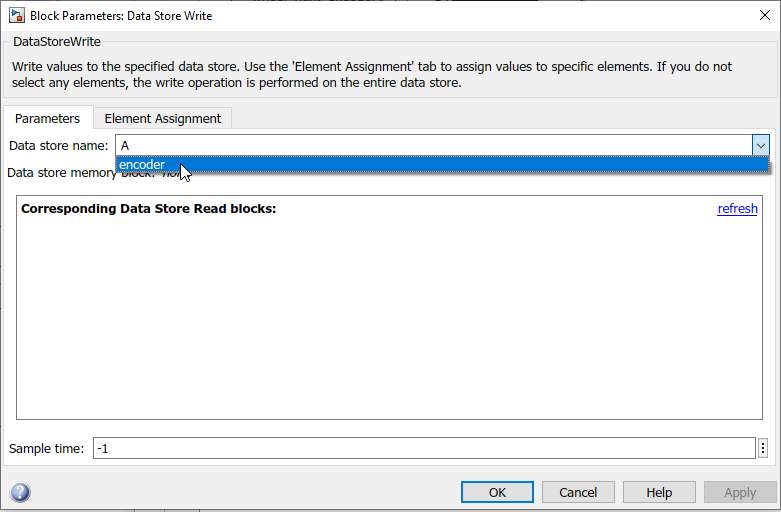
Figure 107: Configure Data Store Write
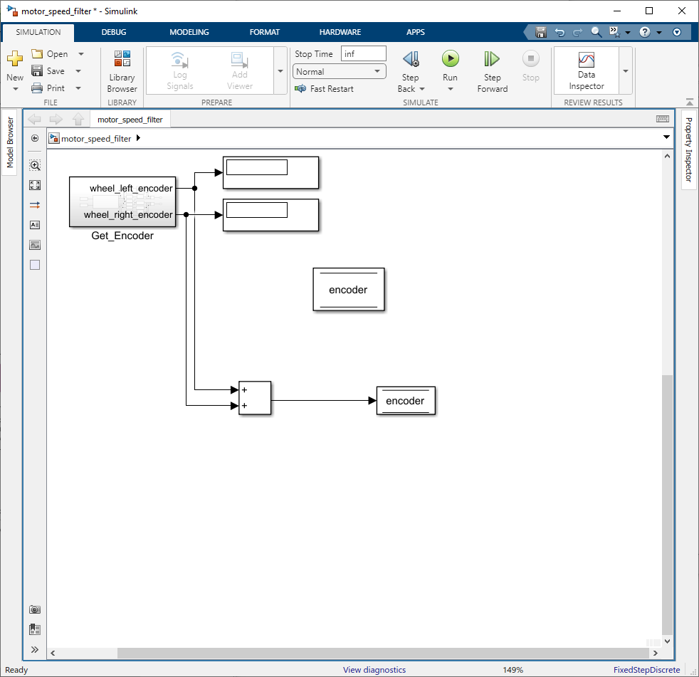
Figure 108: Connect the output of Add block to Data Store Write block
Step 04: Copy and Paste two "Data Store Memory" block and Configure for last_encoder and motor_speed
Copy and Paste two "Data Store Memory" block from 'encoder'. Double-click on the Data Store Memory block to open its configuration parameters. Set Data store name to "last_encoder" and "motor_speed". Keep the Data type to int32 of the last_encoder and change the Data type to single of the motor_speed .
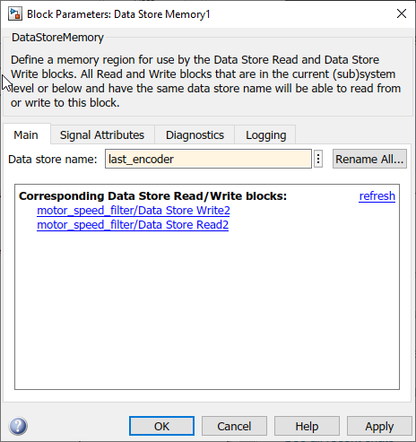
Figure 109: Set laste_encoder as name
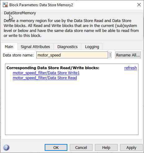
Figure 110: Set motor_speed as name
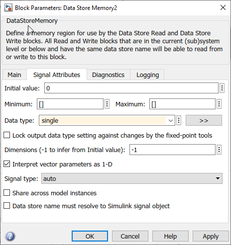
Figure 111: Change data type to single on motor_speed
Step 05: Implement the motor speed filter
Use basic Simulink blocks to create the motor speed filter as following image shows. Use "Data Store Memory" block to store data while using "Data Store Write" & "Data Store Read" blocks to write and read data from it.
Equation:
Implementation:
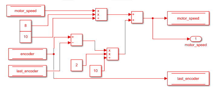
Figure 112: Motor speed filter implementation on simulink
Step 06: Create Subsystem and Connect to Output
Select blocks used for the motor speed filter and right-click and select Create Subsystem from the drop down. Then connect the output of the subsystem to Display blocks.
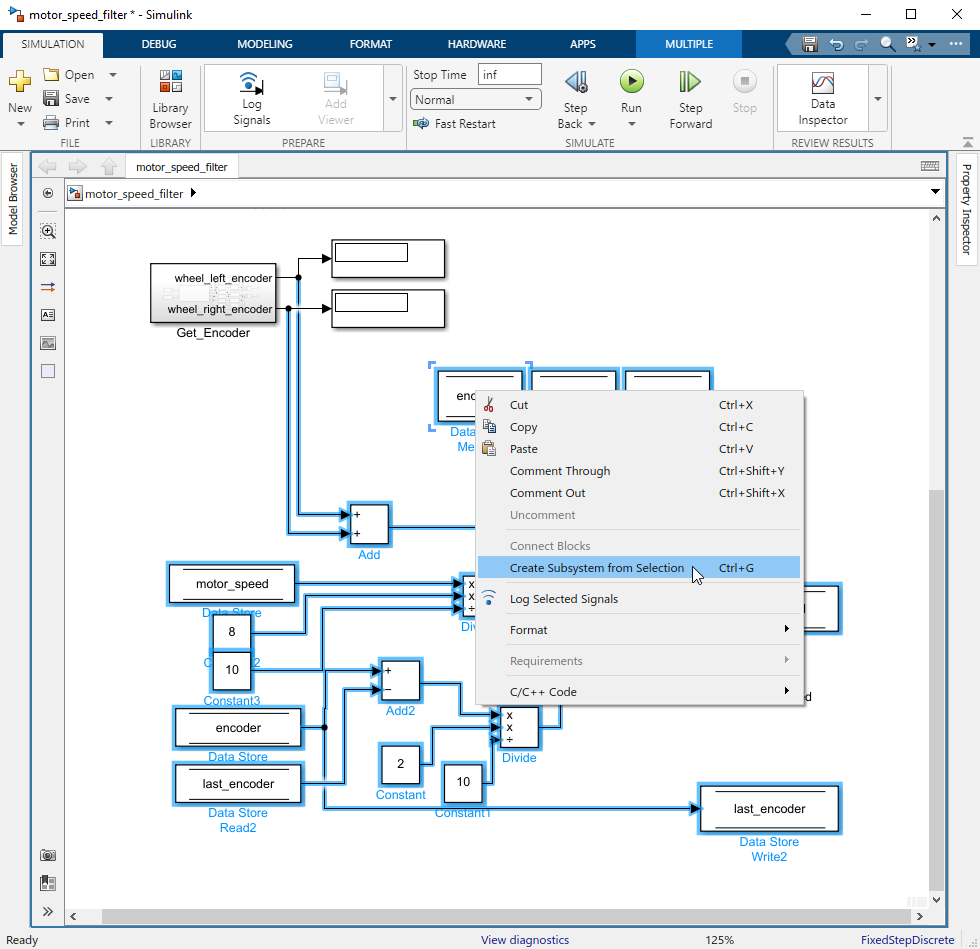
Figure 113: Create Subsystem
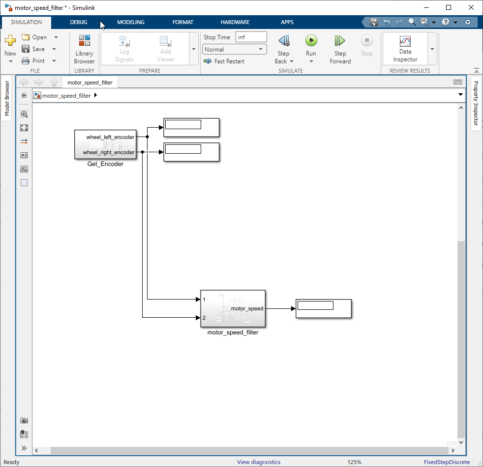
Figure 114: Connect to a Display block
Step 07: Fix the Execution order
Right-click on blocks and select properties to open up Block properties. In that set Priority to set the execution order (start with 0). The reason for this is to ensure that the current encoder value is set to the ‘last_encoder’ value after the calculation is completed.
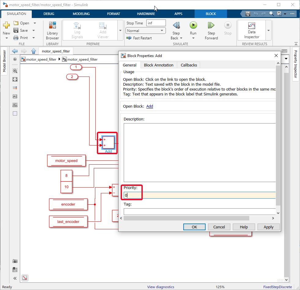
Figure 115: Set Priority to 0 on first Add block
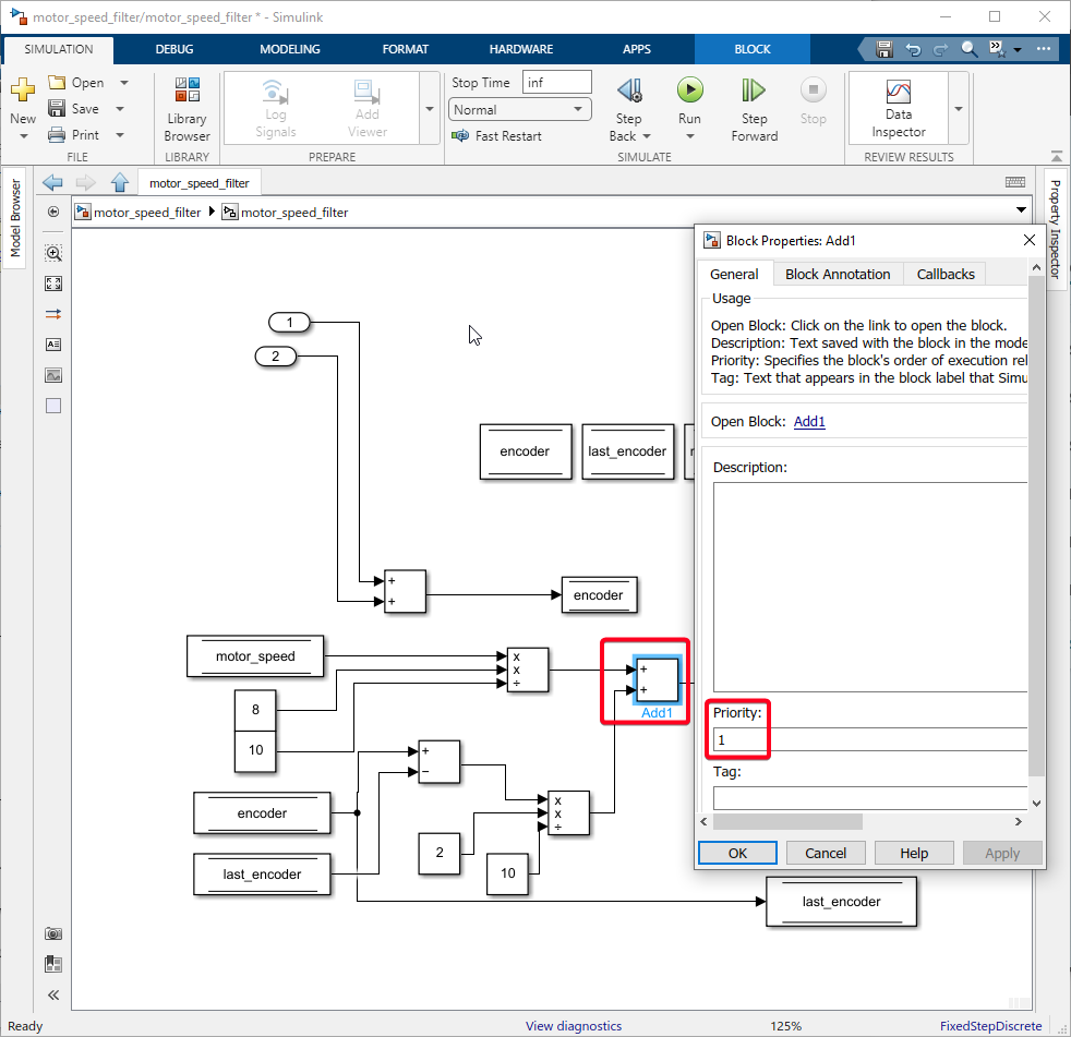
Figure 116: Set Priority to 1 on Add1 block
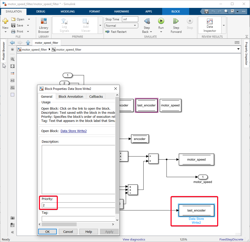
Figure 117: Set Priority to 2 on last_encoder
To check the current execution order right-click on the canvas and select Other Displays>Blocks>Sorted Execution Order.
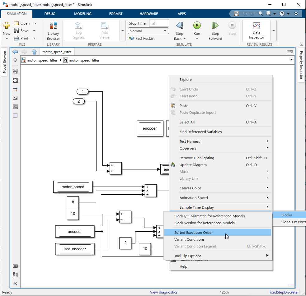
Figure 118: Select Sorted Execution Order
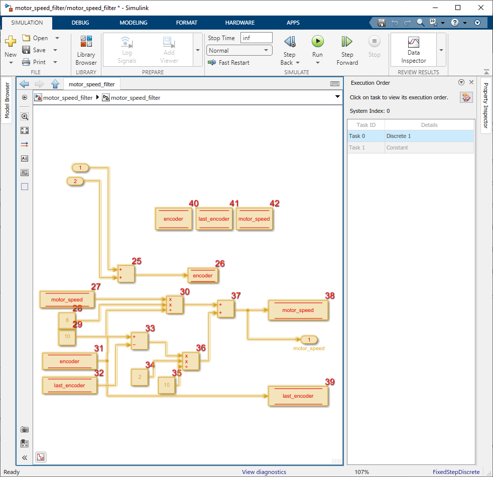
Figure 119: Sorted Execution Order
Example Simulink Model: br_motor_speed_filter.slx