Project description
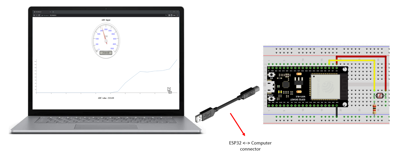
In this project, you will learn how to display ADC readings and voltage drop of a LDR sensor on a graph and gauge, as shown below.
Learning objectives
In this tutorial you will learn:
1.How to configure ESP32 as a web server (Access Point - AP mode) for data acquisition application
2.Understand how to develop HTML, CSS, and JavaScript to display embedded system status on a webpage
3.How a change in surrounding brightness causes a change in resistance and voltage drop of a LDR sensor.
4.How to make the ESP32 a Stand-Alone data acquisition device
Required hardware
No. |
Item |
Picture |
Quantity |
1 |
ESP32 with USB cable |
|
1 |
2 |
Protoboard (830 points) |
|
1 |
3 |
Jumper Wire Male-Male |
|
2 |
4 |
LDR sensor |
 |
1 |
5 |
Resistor 2k Ohms |
|
1 |
6 |
USB Wi-Fi dongle (only necessary in WiFi AP mode) |
|
1 |


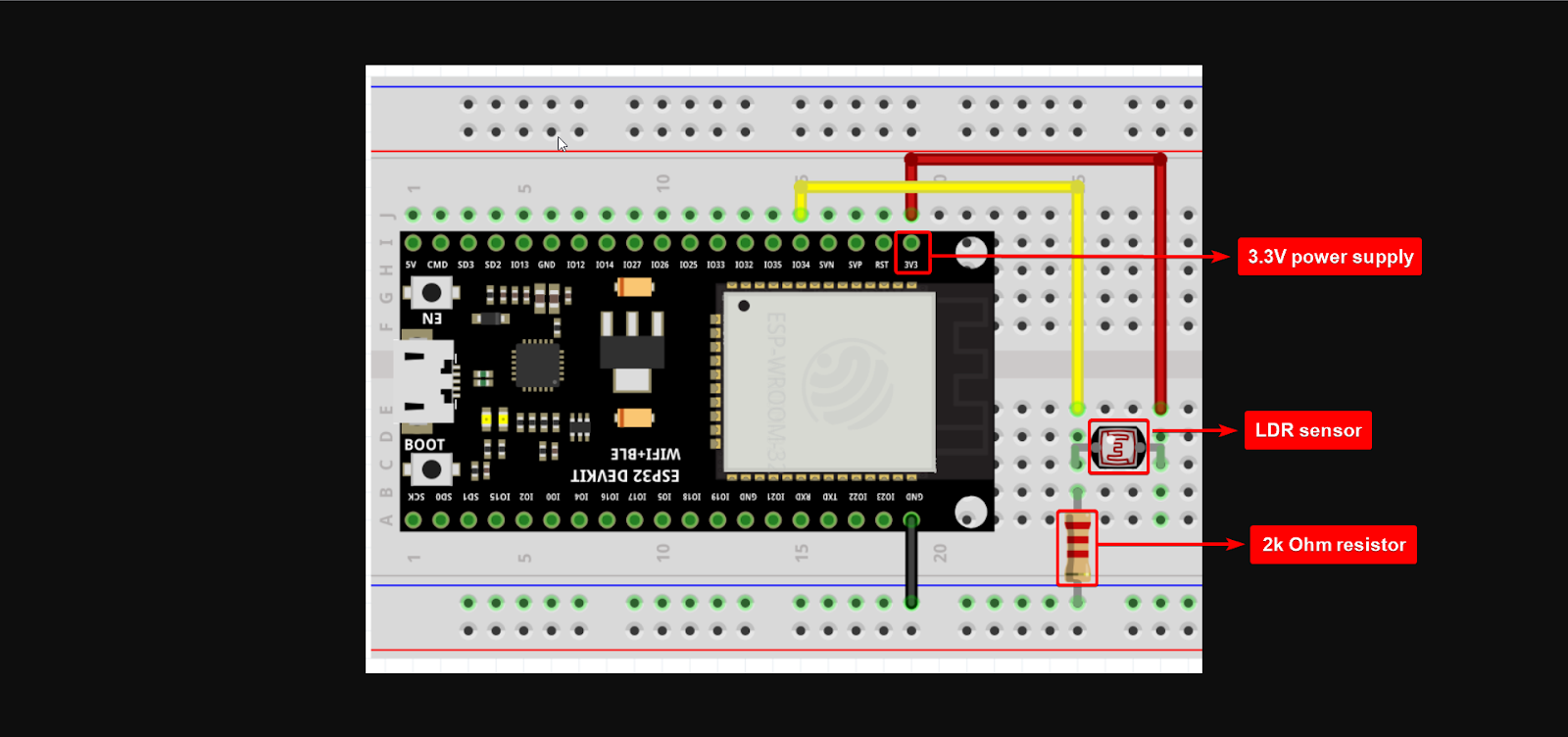
Hardware setup
Hands-On
Stand-Alone (SA)
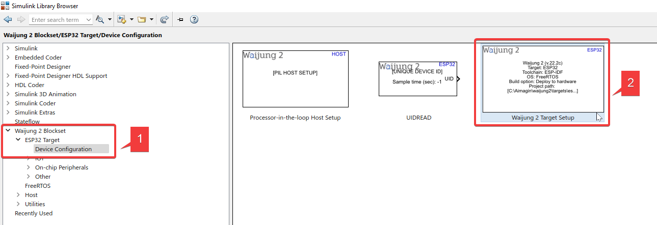
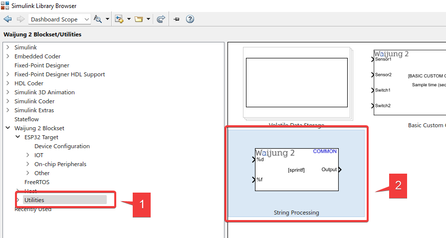
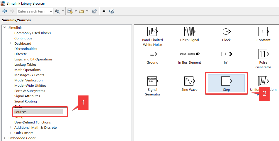
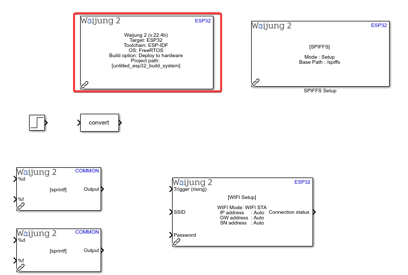
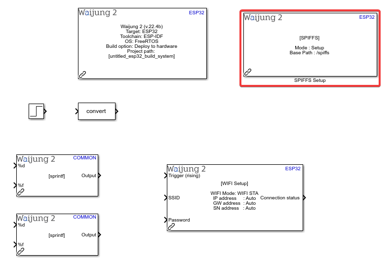
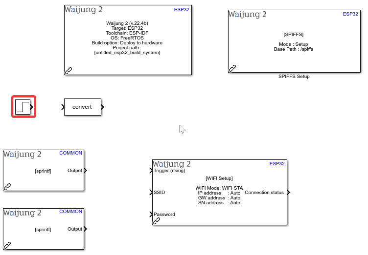
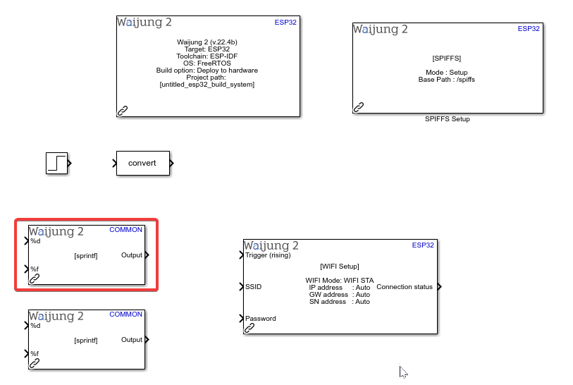
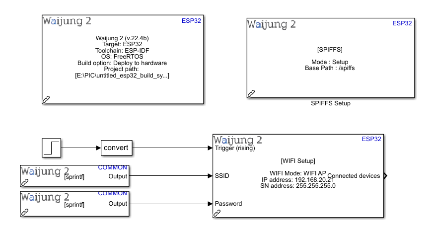
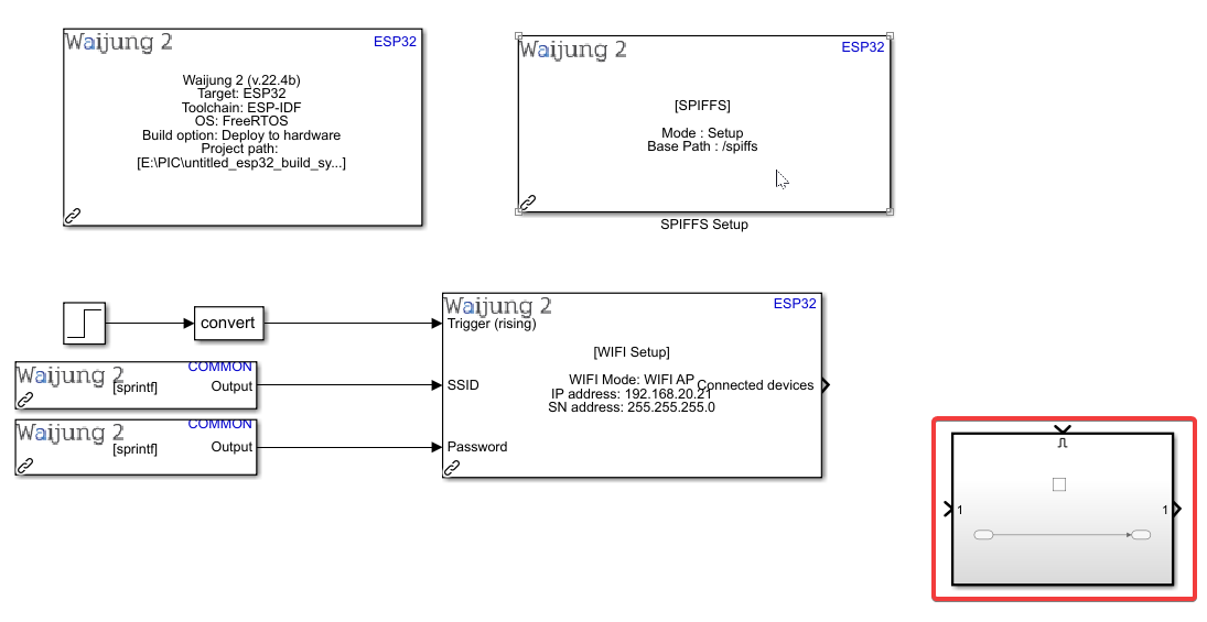
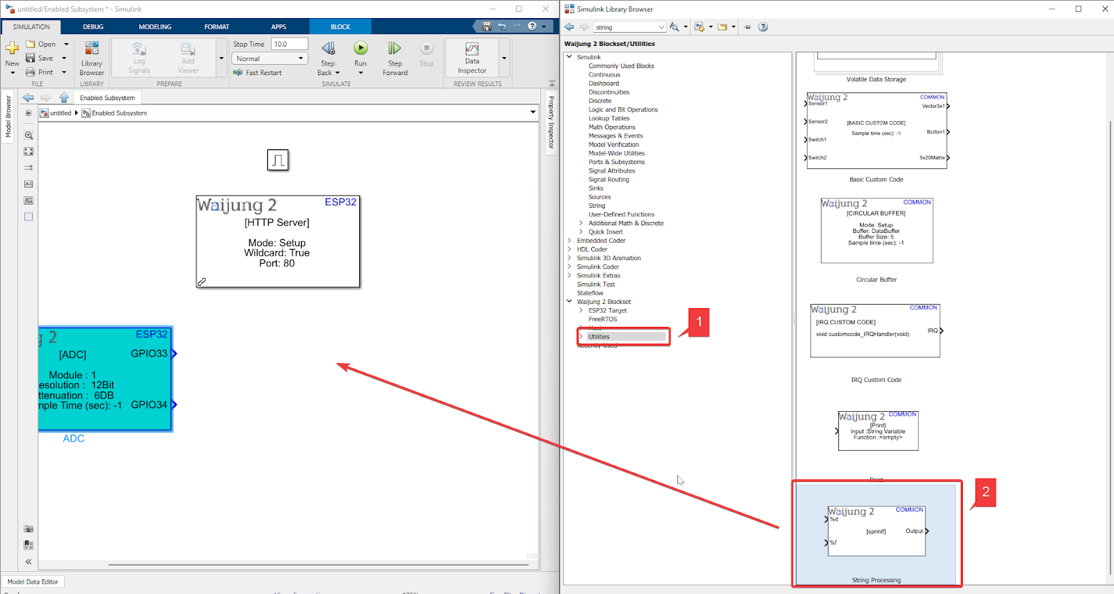
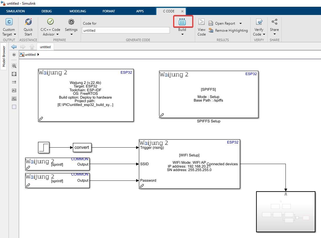
1. Import Waijung 2 Target Setup block and two String Processing blocks from Library Browser
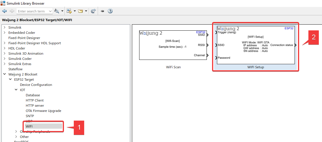
2. Import WIFI Setup block and Step block
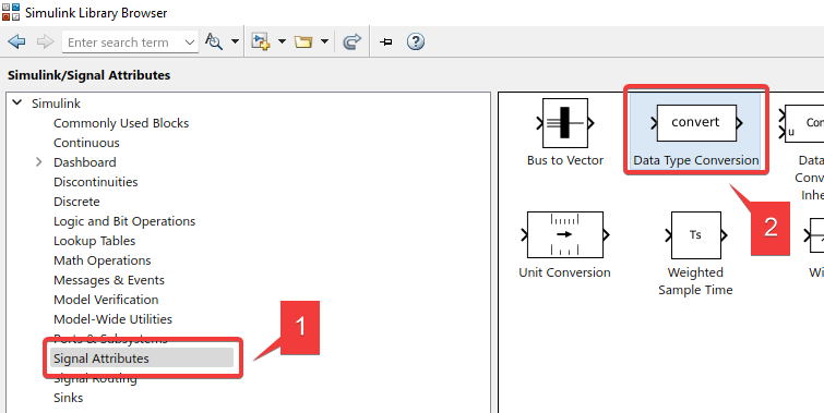
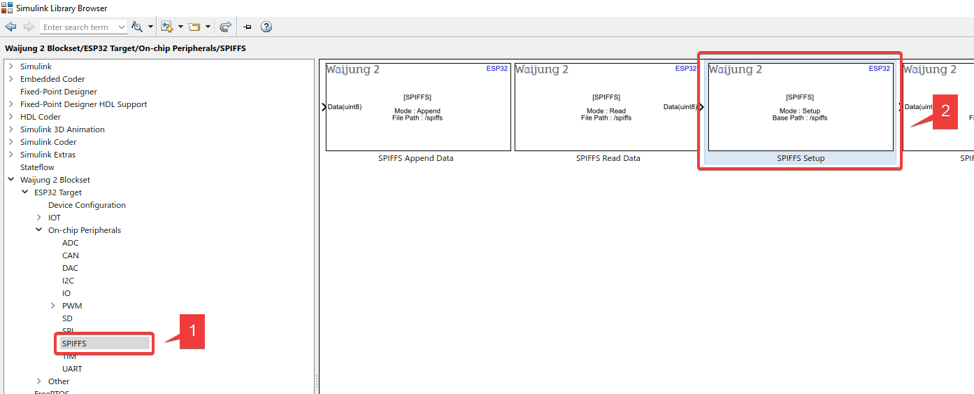
3. Import Data Type Conversion block and SPIFFS Setup block
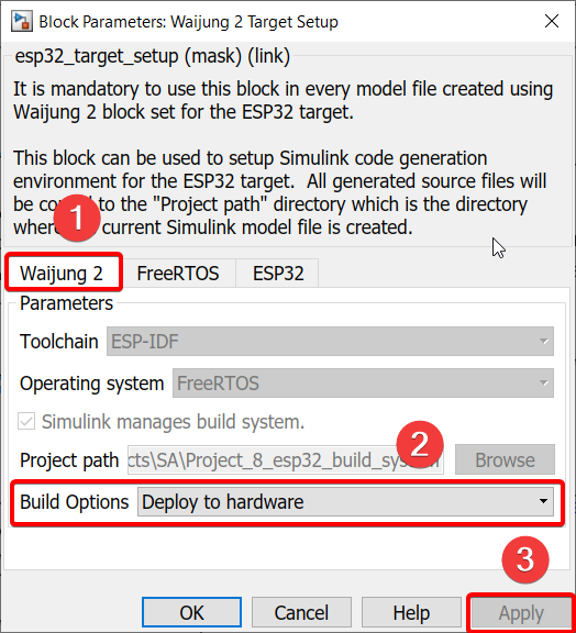
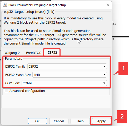
4. Configure Waijung 2 Target Setup block according to the following
5. Under “FreeRTOS”, change the default value of “Default xTaskCreate_stack depth” to 10240
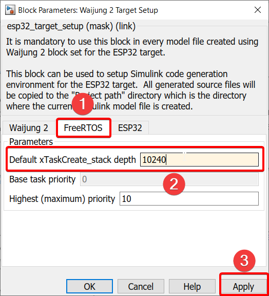
Explanation
Stack depth refers to the space allocated for the task that is being created: the higher the stack depth is, the more memory storage required by ESP32
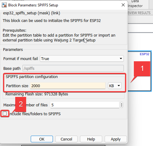
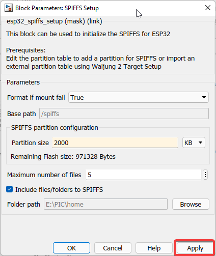
6. Double-click SPIFFS Setup block
7. Change the value of Partition Size to 2000 KB and tick “Include files/folders to SPIFFS”
Explanation
SPIFFS refers to the external storage for ESP32
Note
If you have an SD card (internal storage) for your ESP32, you will not need the SPIFFS block. You will use the “SD” related blocks from the Waijung blockset in that case.
In our case, we need SPIFFS as this is where we must store our HTML code, CSS file, and Javascript file that we used to create the webpage.
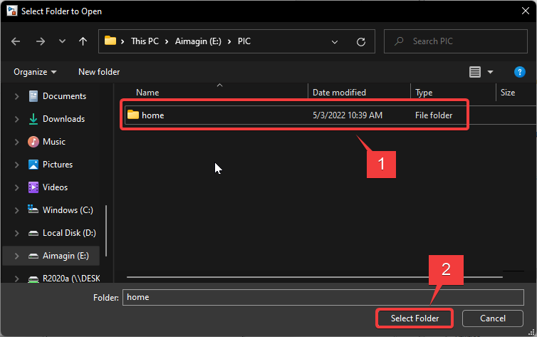
8. After the “Include files/folders to SPIFFS” option is ticked, browse for the folder where the files are stored.
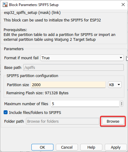
Explanation
After the model is built using Waijung, the selected folder is automatically accessed in order to create the webpage with the defined IP address through which the hardware can be controlled.
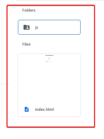
9. You can download the source files needed for the webpage here and also at the end of the project. Please extract both files into the same folder as shown below.
10. Click Apply
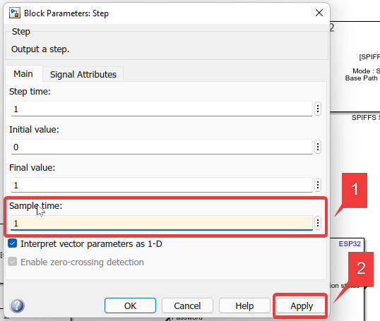
11. Double-click the Step block
12. Set “Sample time” as “1” (this means that all values will be updated every 1 second, so that the webpage can be refreshed every 1 second)
13. Double-click the WiFi Setup block
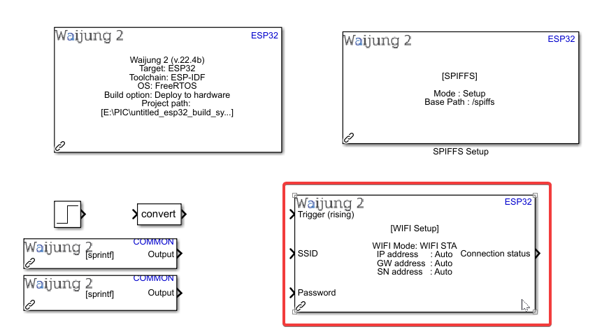
14. For WIFI AP mode:
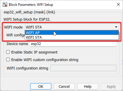
Explanation
Wi-Fi AP = Wi-Fi Access Point
Since ESP32 has Wi-Fi capabilities, we are making it an access point.
Other examples of access points: Wi-Fi router at our home, Hotspot from our mobile phone.
Once this access point is created, we can connect to it using our external USB Wi-Fi dongle.
15. Double-click the second String Processing block
16a. Under “Format”, set the Wi-Fi SSID name and click Apply. You can choose to use either WiFi AP or WiFi STA mode.
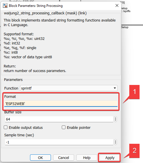
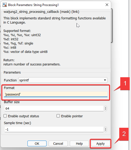
16b. Double-click the second String Processing block
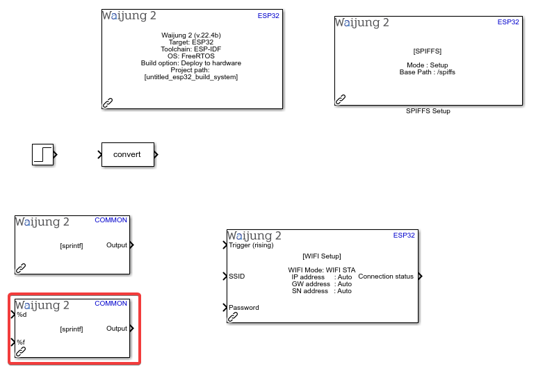
17. Under “Format”, set the Wi-Fi password and click Apply
18. Click Apply after IP address and Subnet mask IP section appear
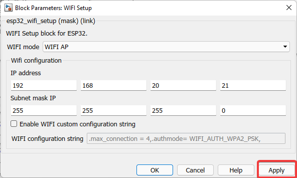
Explanation
Default settings of both ‘IP address’ and ‘Subnet mask IP’ can be used. You can also set your own.
The IP address set will be used to access the webpage that you have created to control the LED.
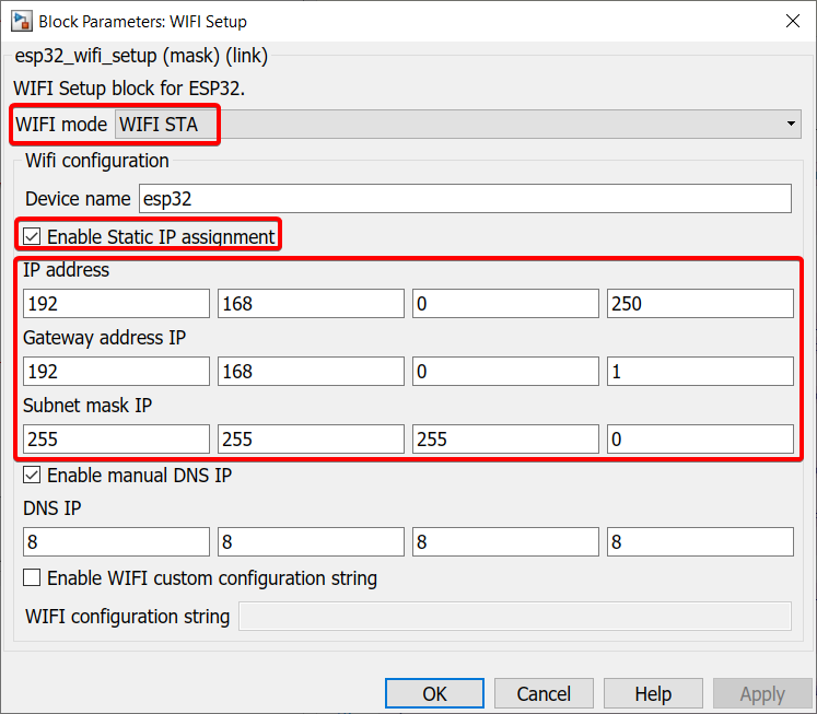
19. For WiFi STA mode:
Set it up by using the SSID and password that your computer uses to connect to the internet through the 2 string processing blocks shown above.
Note: All ESP32 boards only support 2.4GHz bandwidth (except the recently released ESP32-C5 which also supports 5GHz), so make sure the WiFi you connect your ESP32 board to in WiFi STA mode lies in the 2.4GHz frequency range
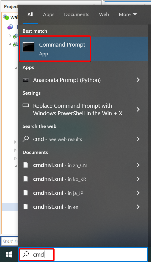
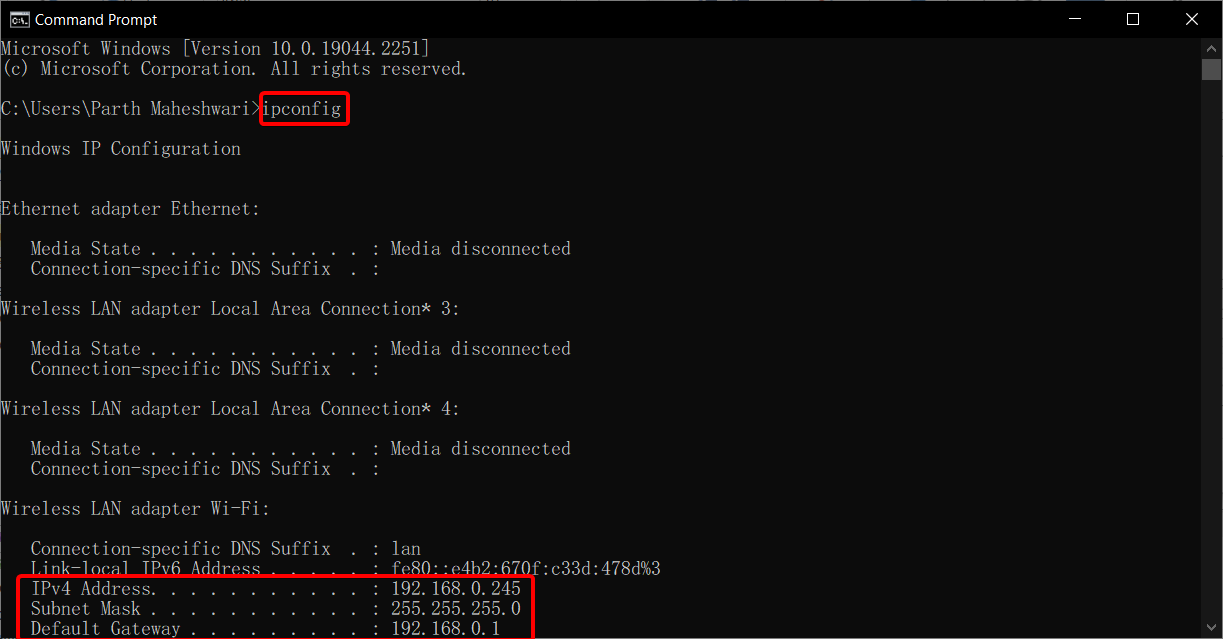
For the IP address, Gateway, and Subnet mask, please search for "command prompt" or "cmd" and type "ipconfig" to find the configurations and input them into the target setup.
Note: For the IP address, choose any number between 0 to 255 for the last 3 digits, except the IPv4 address listed in command prompt (since that is the IP address assigned to your computer).
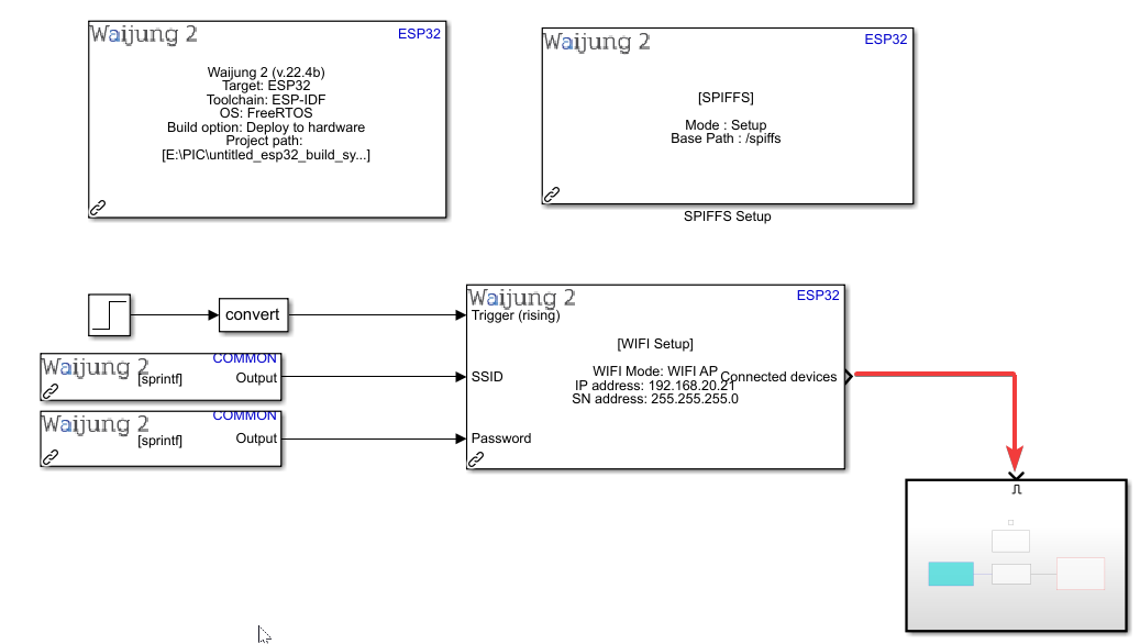
20. Connect everything as shown below
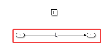
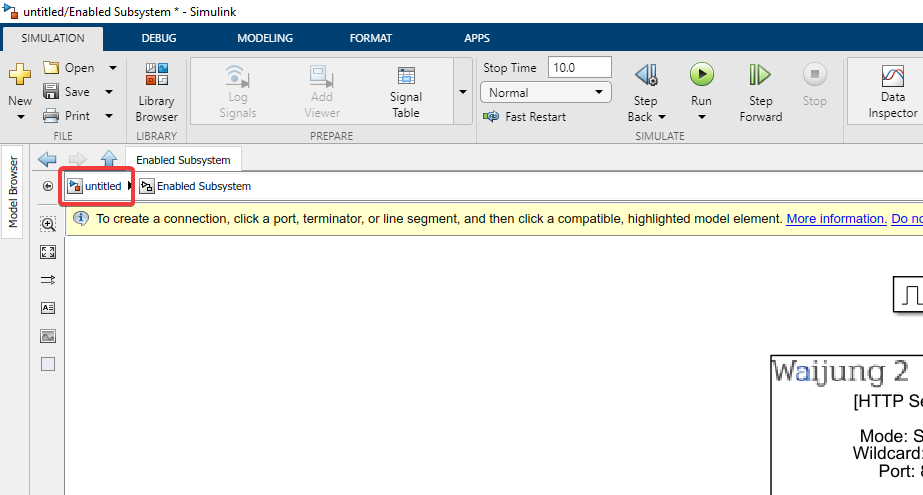
21. Drag the mouse in an empty area of the model
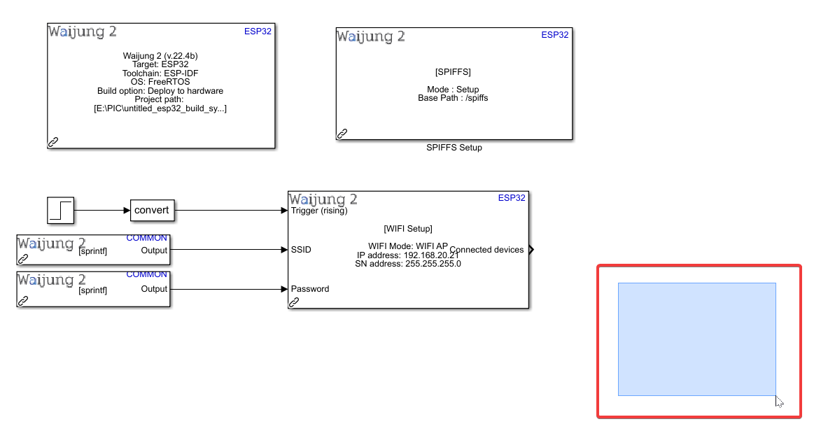
22. Select “Enabled Subsystem”
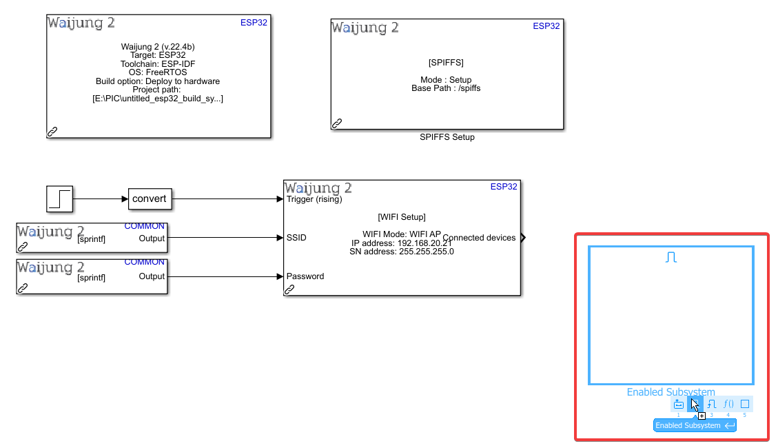
23. Double-click to enter the subsystem
24. Delete the following
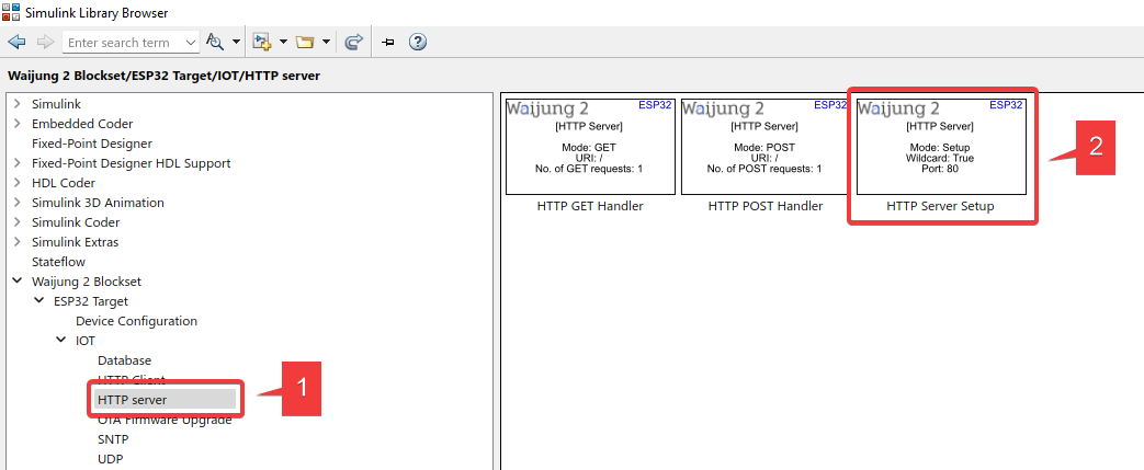
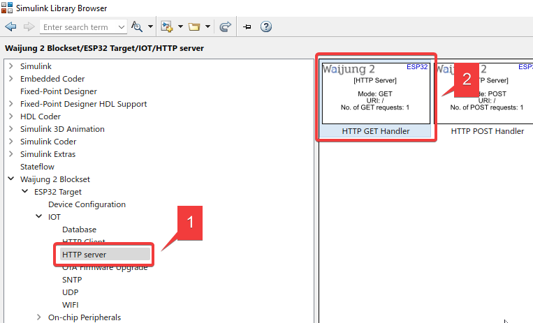
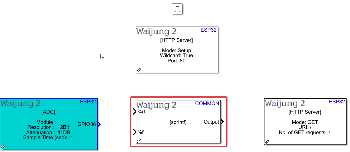
25. Import HTTP Server Setup and HTTP GET Handler blocks
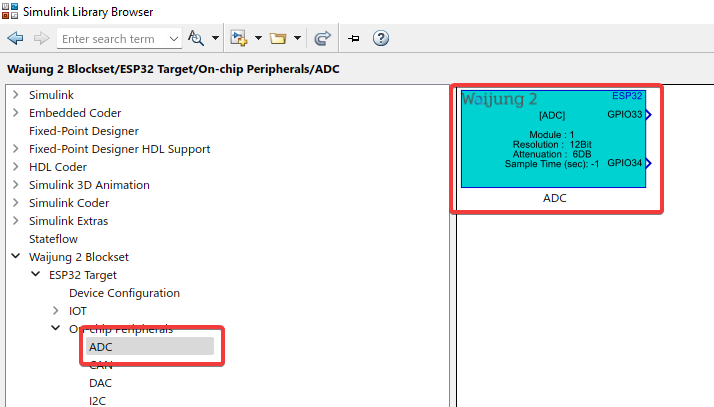
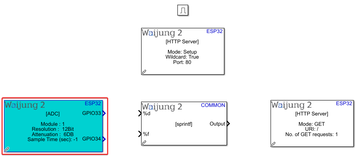
26. Import ADC block
27. Import String Processing block
28. Import HTTP GET Handler block
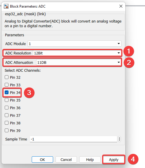
29. Double-click ADC block
30. Configure as shown
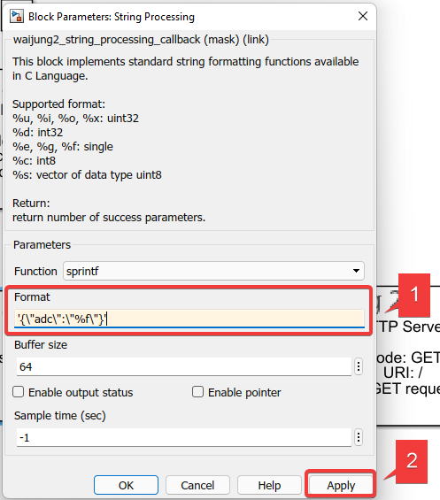
31. Double-click String Processing block
32. Enter the following under “Format”
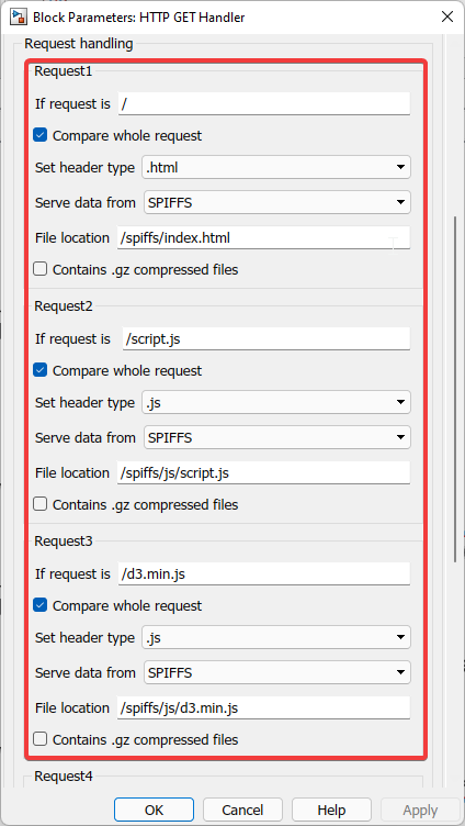
33. Double-click HTTP GET Handler block
34. Enter the information as shown
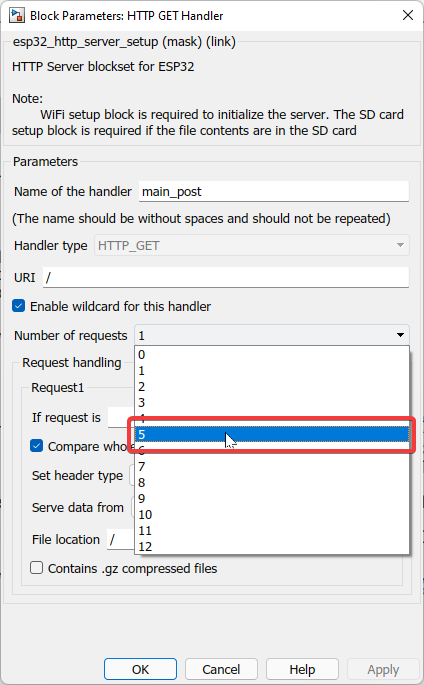
Explanation
In this project, five files are used to create the webpage (1 HTML and 3 JS). This block is used to extract the information from those files, so a request is sent to both of them. However, we need to send five requests because we want to extract information from a specific “json” section within the script.js file at every time step as well.
35. Enter the information as shown and click Apply
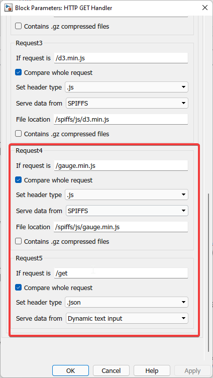
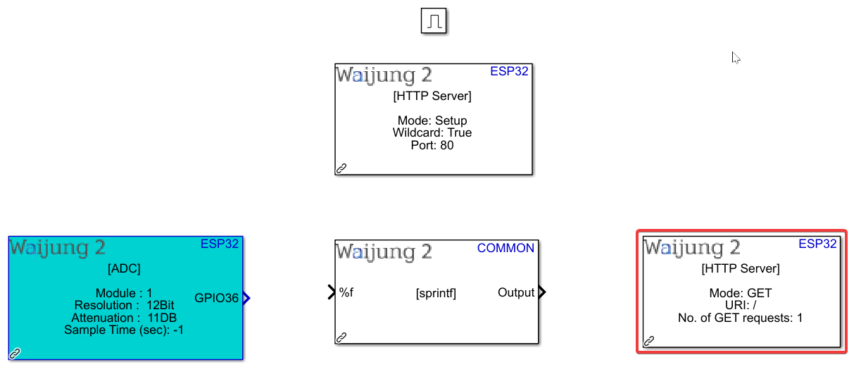
36. Connect everything as shown
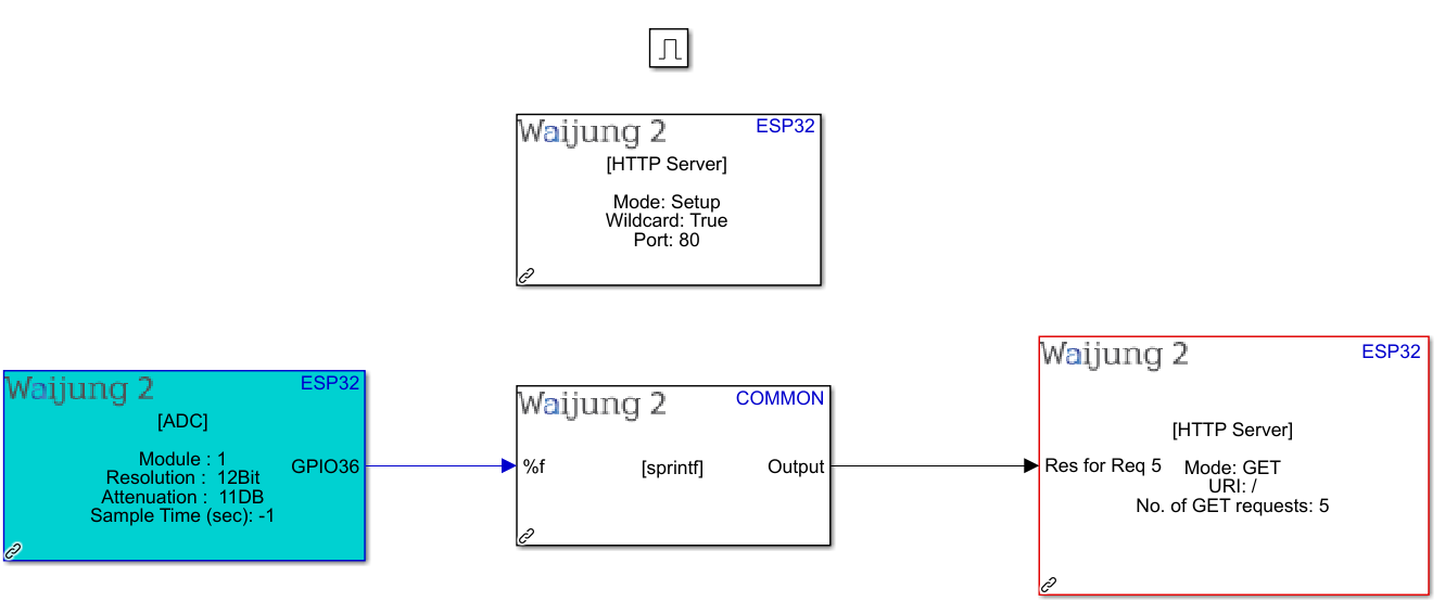
37. We are still in the subsystem; go back to the model’s default page
38. Connect accordingly
39. Save the file in the correct directory
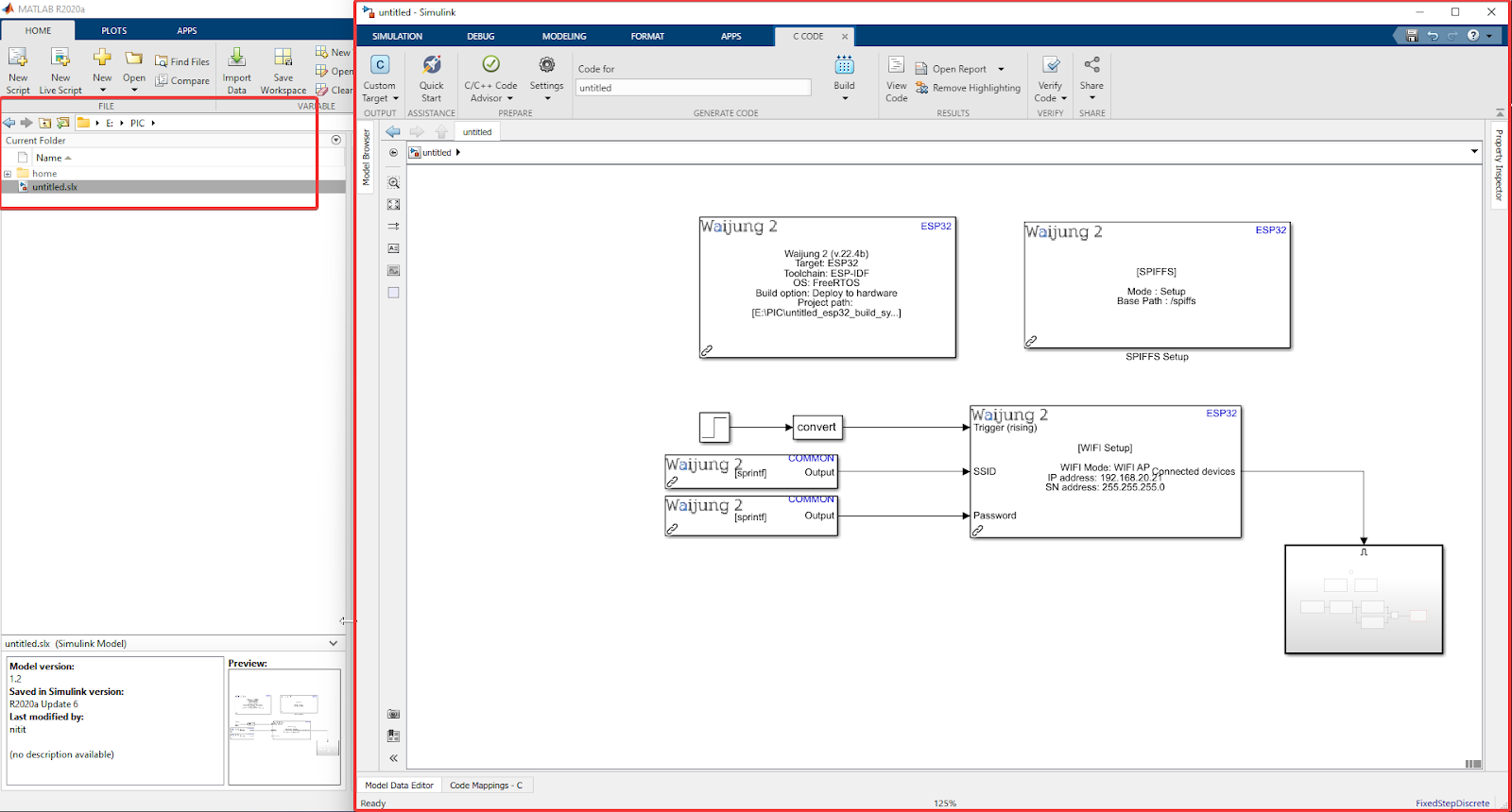
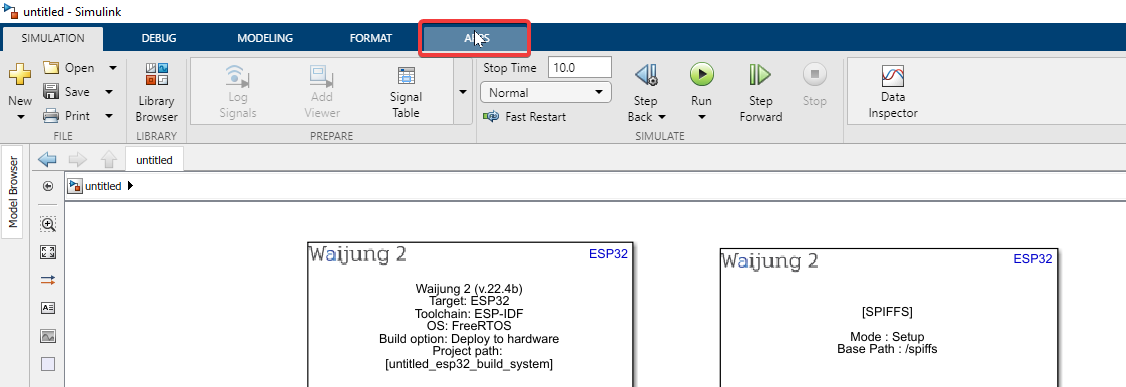
40. Go to “APPS”
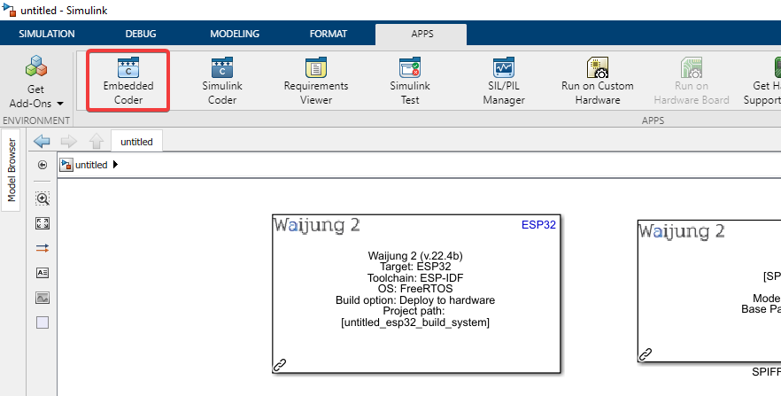
41. Click “Embedded Coder”
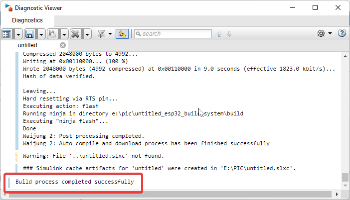
42. Click “Build” to compile the model
43. Build process completed successfully
Note: For users who have chosen WiFi STA mode, please skip to Step 45. Step 44 is only for users who have chosen WiFi AP mode.
44. Connect to the Wi-Fi set earlier for the WIFI Setup block
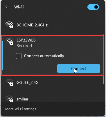
Note
You can access this Wi-Fi access point on your computer or your mobile phone on any operating system. Once the webpage is set up, it is easy to access from several devices in order to control the hardware.
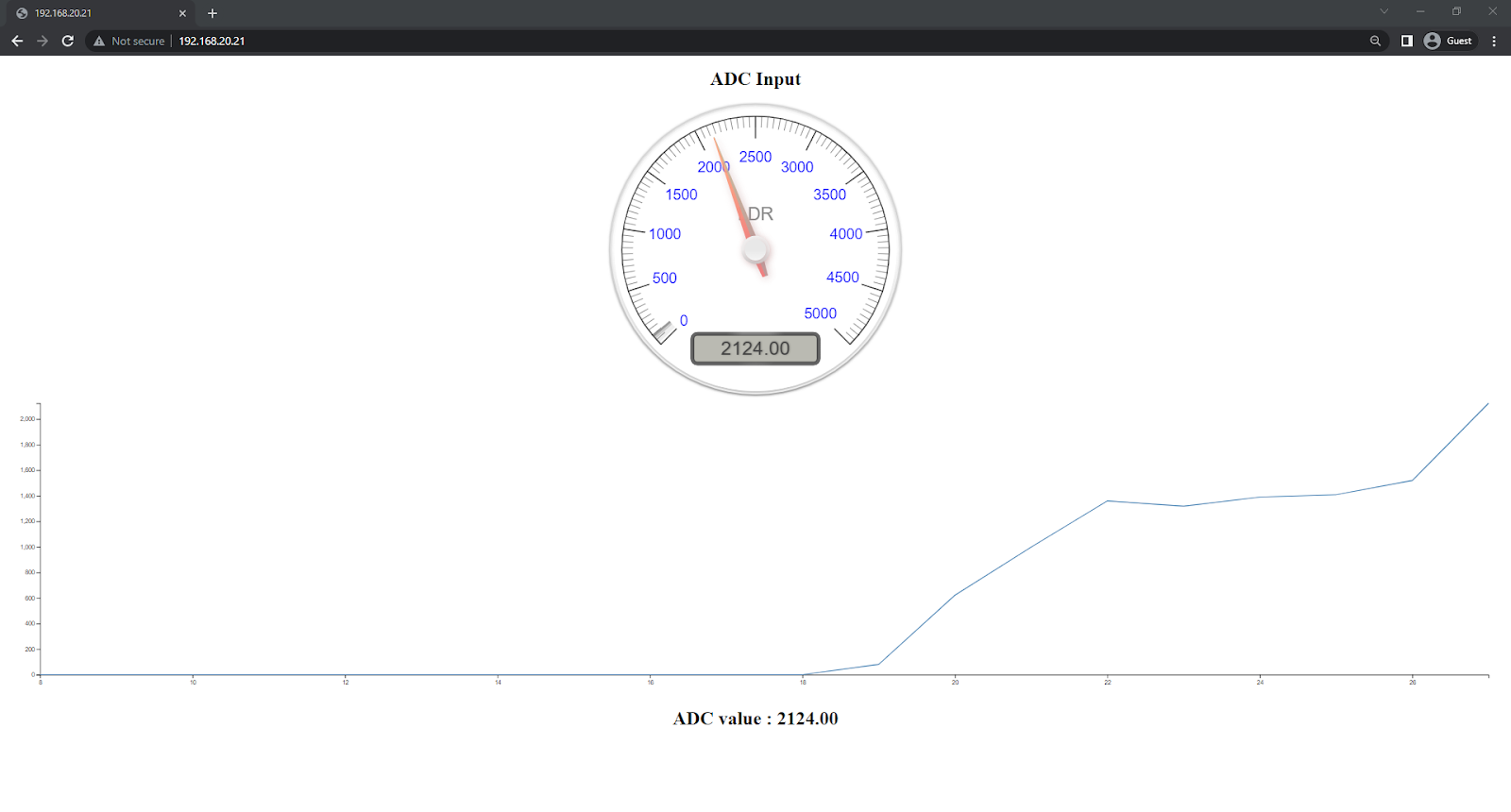
45. Go to the webpage IP address that you set up.
For WiFi AP mode, we have used the default address of 192.168.20.21
For WiFi STA mode, we have used the address of 192.168.0.250
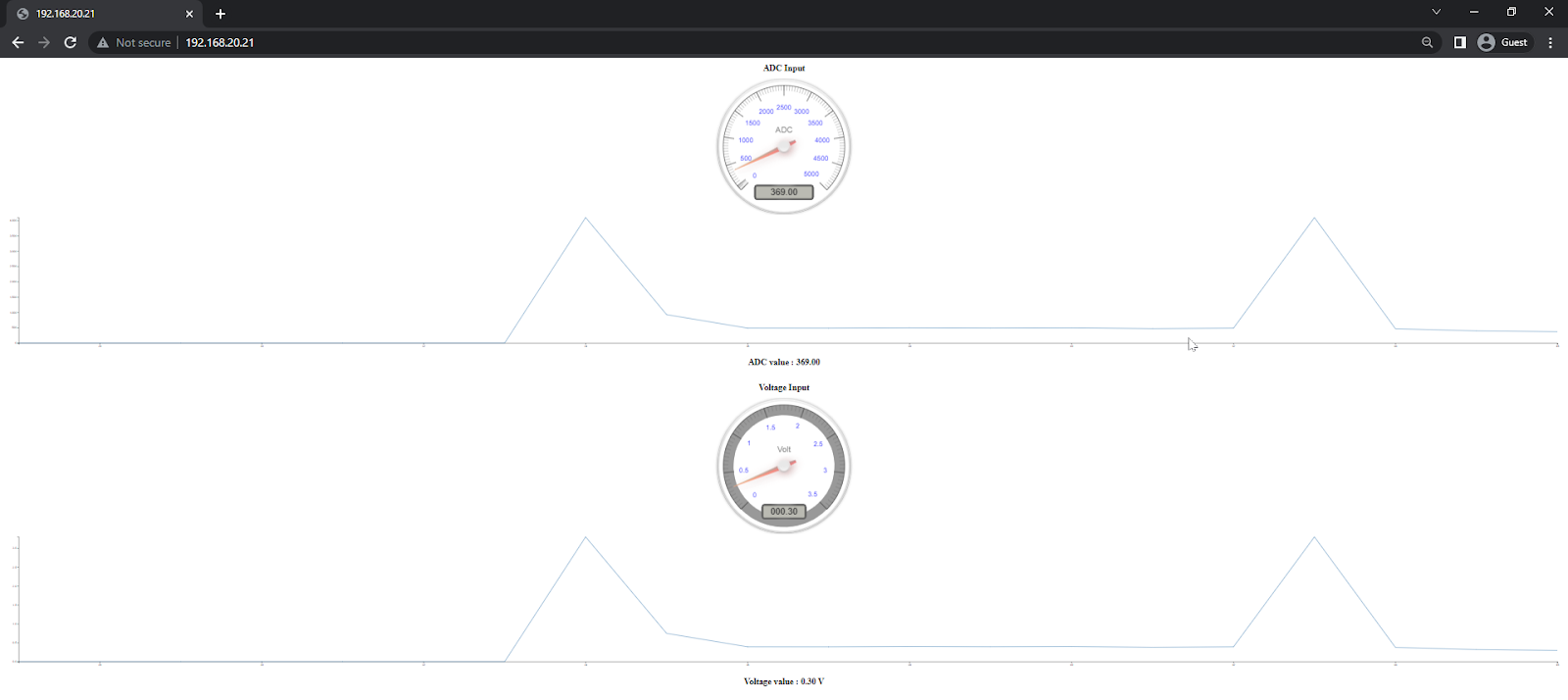
46. You will enter a web page looking like this
47. You can test and see the working of the system. Click to view video
Explanation
When the light falling on the LDR changes, its resistance changes. Due to this, the voltage drop across it changes as well. Hence, there is a change in the ADC value as shown.
Explanation of HTML source code
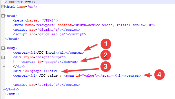
1.Heading name
2.Building a gauge
3.Building a graph
4.ADC value
Explanation of script.js file
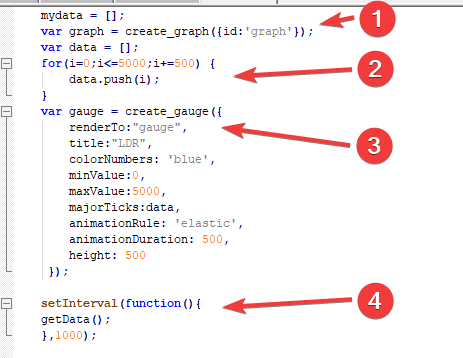
1.Create a graph
2.Set range for the gauge
3.Build gauge
4.Function getData() is called every 1000 milliseconds = 1 second
Explanation of getData() subsection file
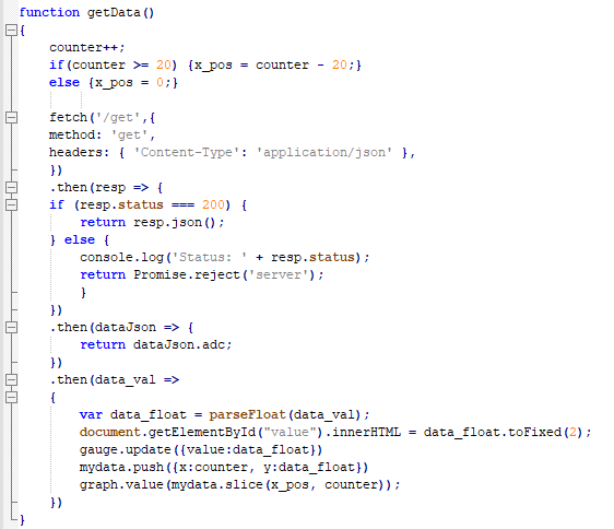
This function is called every time a “/get” tag is used. Under this function, the graph is extended as time goes on. The values are also updated according to the LDR input.
This is the end of this tutorial. To apply your learning, you can test yourself with a practice problem.
Exercise
Add another graph to show the voltage drop across the circuit. Conduct SA.
Reference: Analog to Digital Converter (ADC) - ESP32