|
Project 11: Complete web-enabled embedded controller and data storage using Aimagin Analytics |
Scroll Prev Top Next More |
Project description
This project will be achieving the same result as Project 10 but we will teach you how to implement the web application using drag and drop tools with minimum code, instead of needing to write a lot of HTML/CSS/JS. We will also teach you how to store the recorded data in a server.
Learning objectives
In this tutorial you will learn:
1.Understand how to implement a web application using drag and drop tools (Aimagin Connect) to control a device.
2.Understand how to configure a server (Aimagin Analytics) to receive data for secure storage and analysis.
Required hardware
No. |
Item |
Picture |
Quantity |
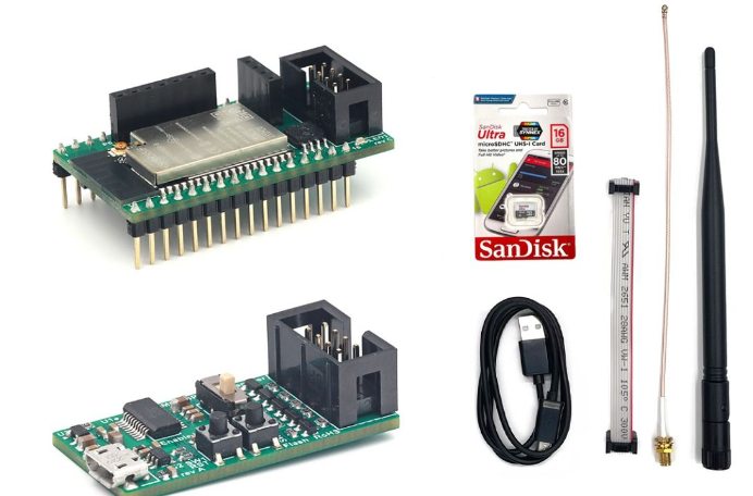
1 |
|
1 |
|
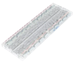
2 |
Breadboard (830 points) |
|
1 |
3 |
Jumper Wire Male-Female |
|
4 |
4 |
Red 5mm LED |
|
1 |
5 |
Resistor 220 Ohms |
|
1 |
6 |
Resistor 2k Ohms |
|
1 |
7 |
LDR sensor |
 |
1 |
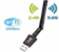
8 |
USB Wi-Fi dongle (only necessary if WiFi AP mode is used) |
|
1 |
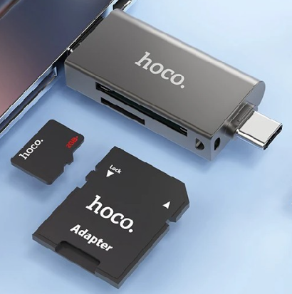
9 |
Micro SD card reader (Example) |
|
1 |


Hardware setup
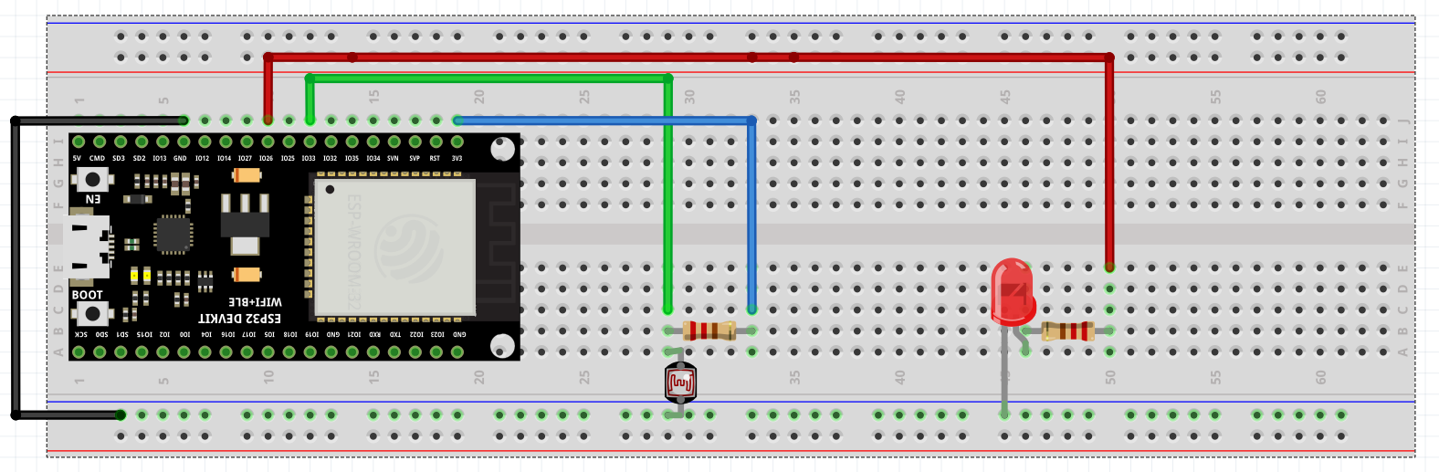
Let's get started on building the web application with Aimagin Connect first.
What is Aimagin Connect?
Aimagin Connect can be used create web applications using drag and drop methodologies for both enterprise and embedded web servers.
PART 1: DESIGN THE WEB APPLICATION
Note: You can download the completed file here, or you can follow the steps and do it yourself as well.
1.Go to https://bidev.aimagin.com/ and sign in to your Aimagin Analytics account.
Credentials needed: Organization ID, Username, Password
Note: Credentials can only be generated by Aimagin.
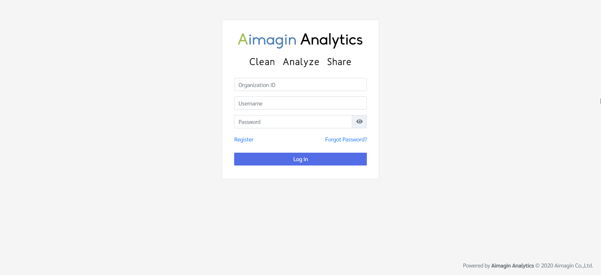
2.Successfully signed in
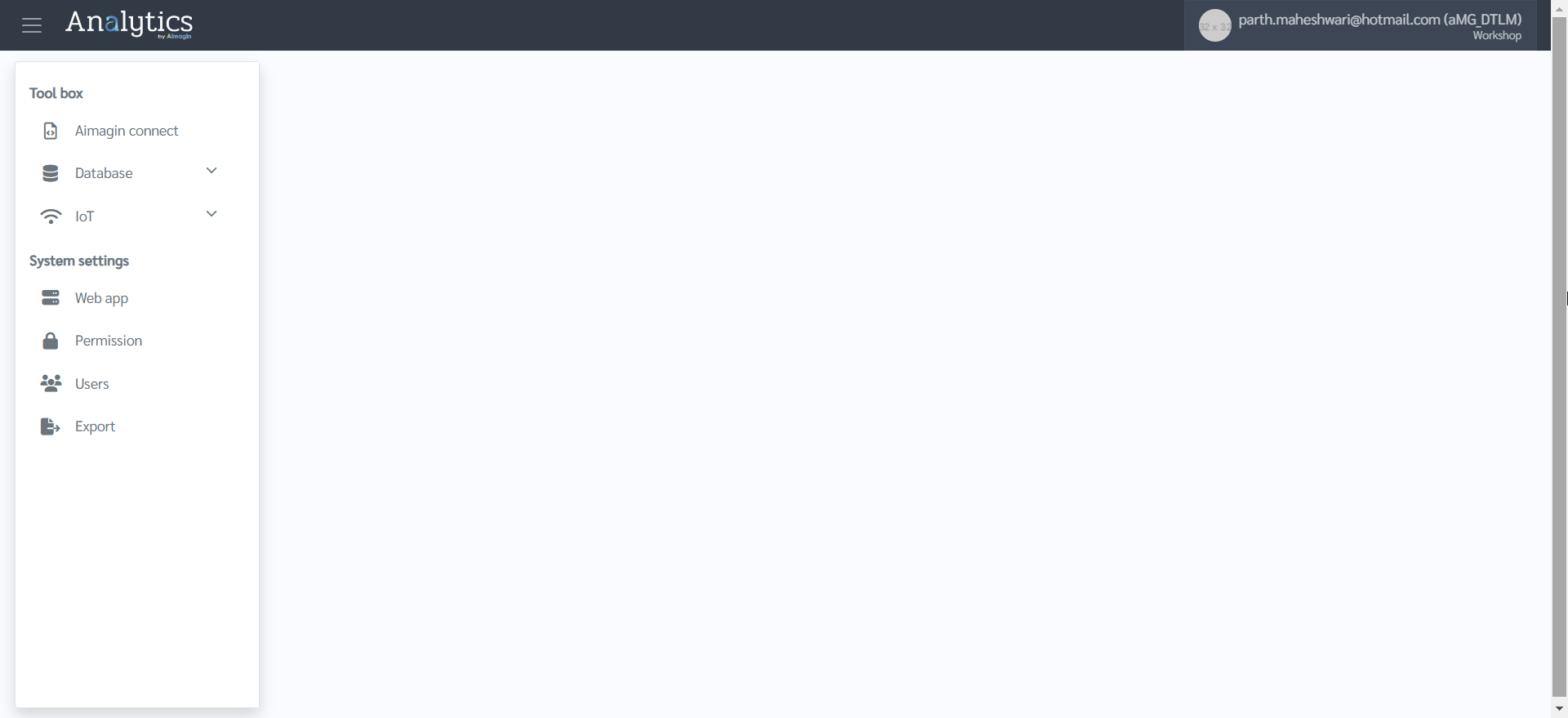
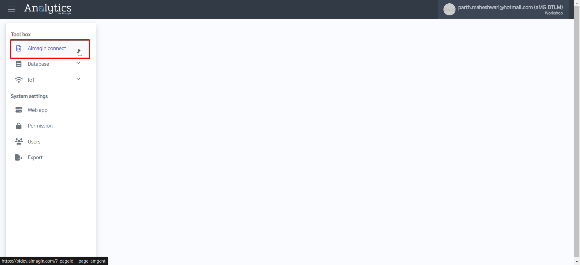
3.Click on Aimagin Connect
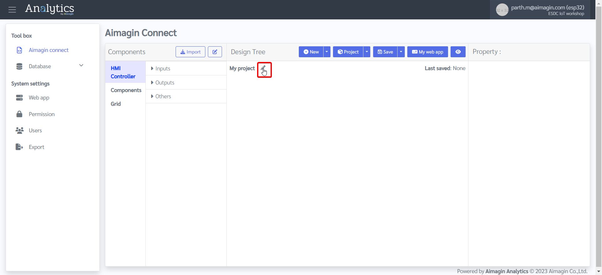
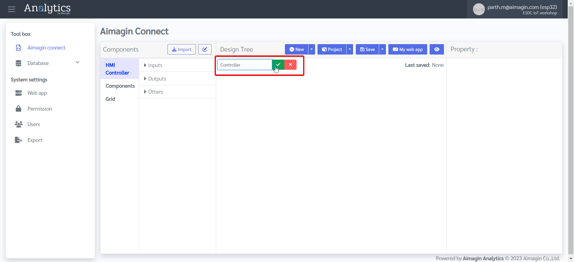
4.Name the project
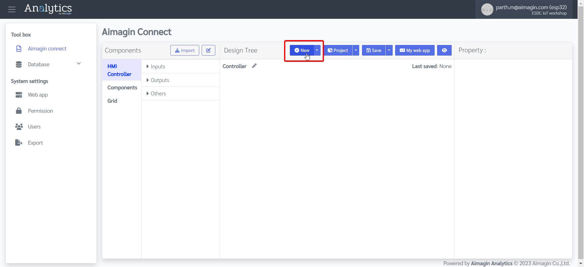
5.Add a new page
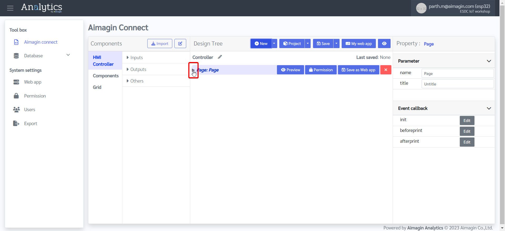
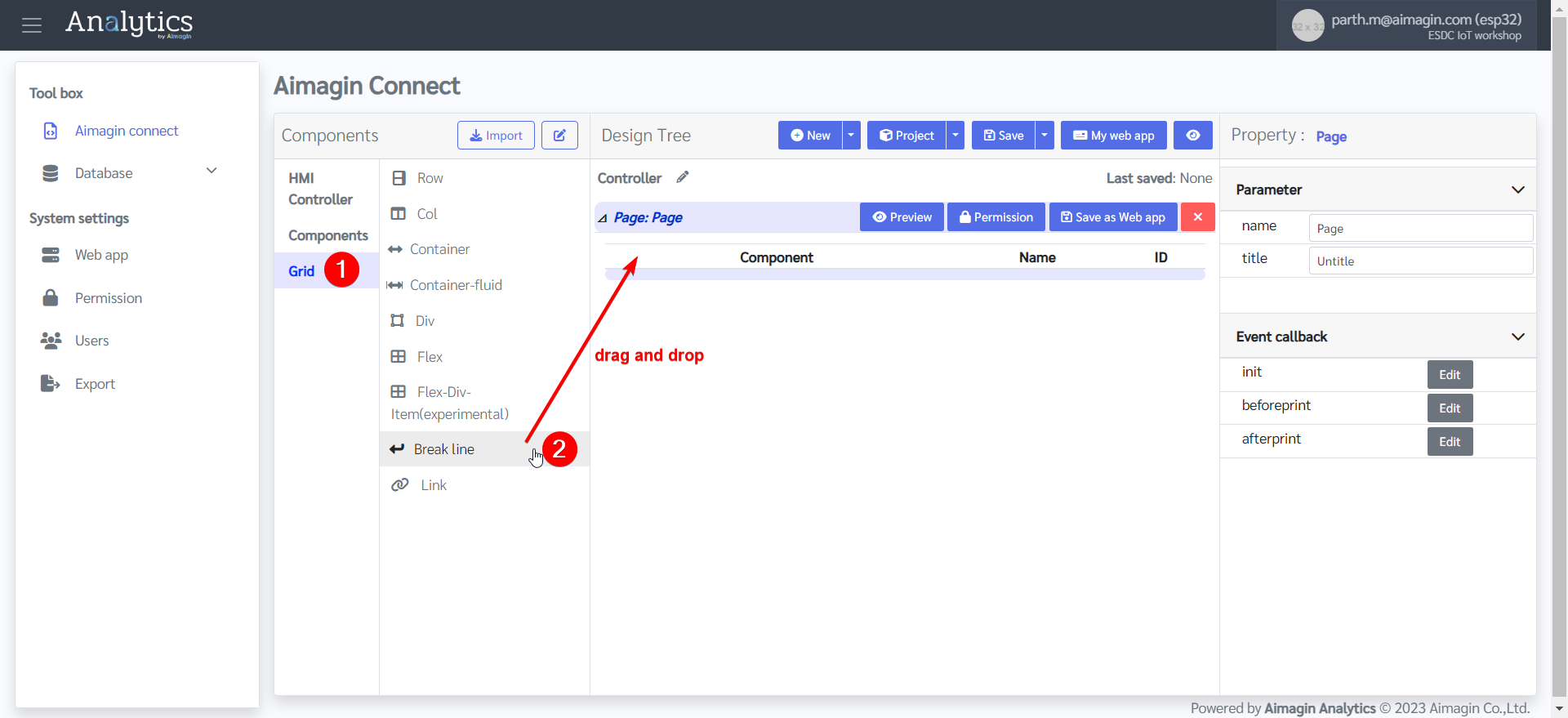
6.Expand the page
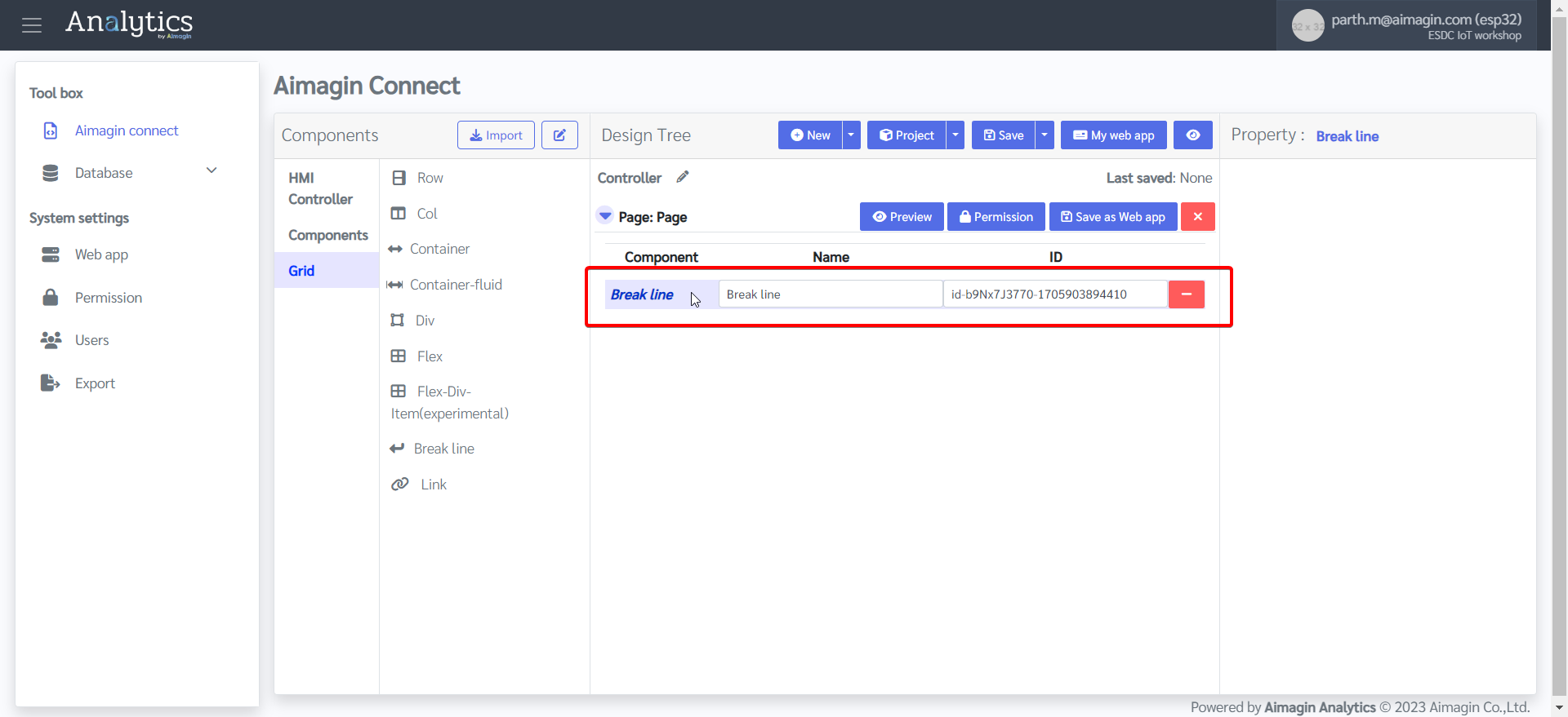
7.Add a Break line by dragging and dropping
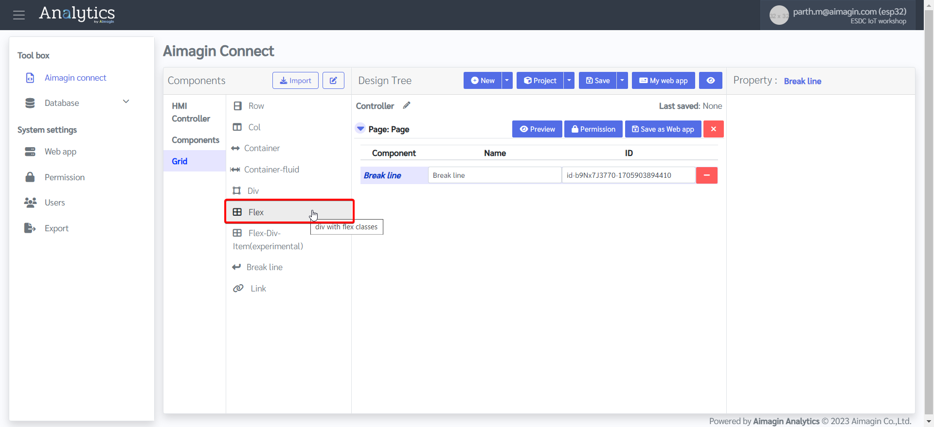
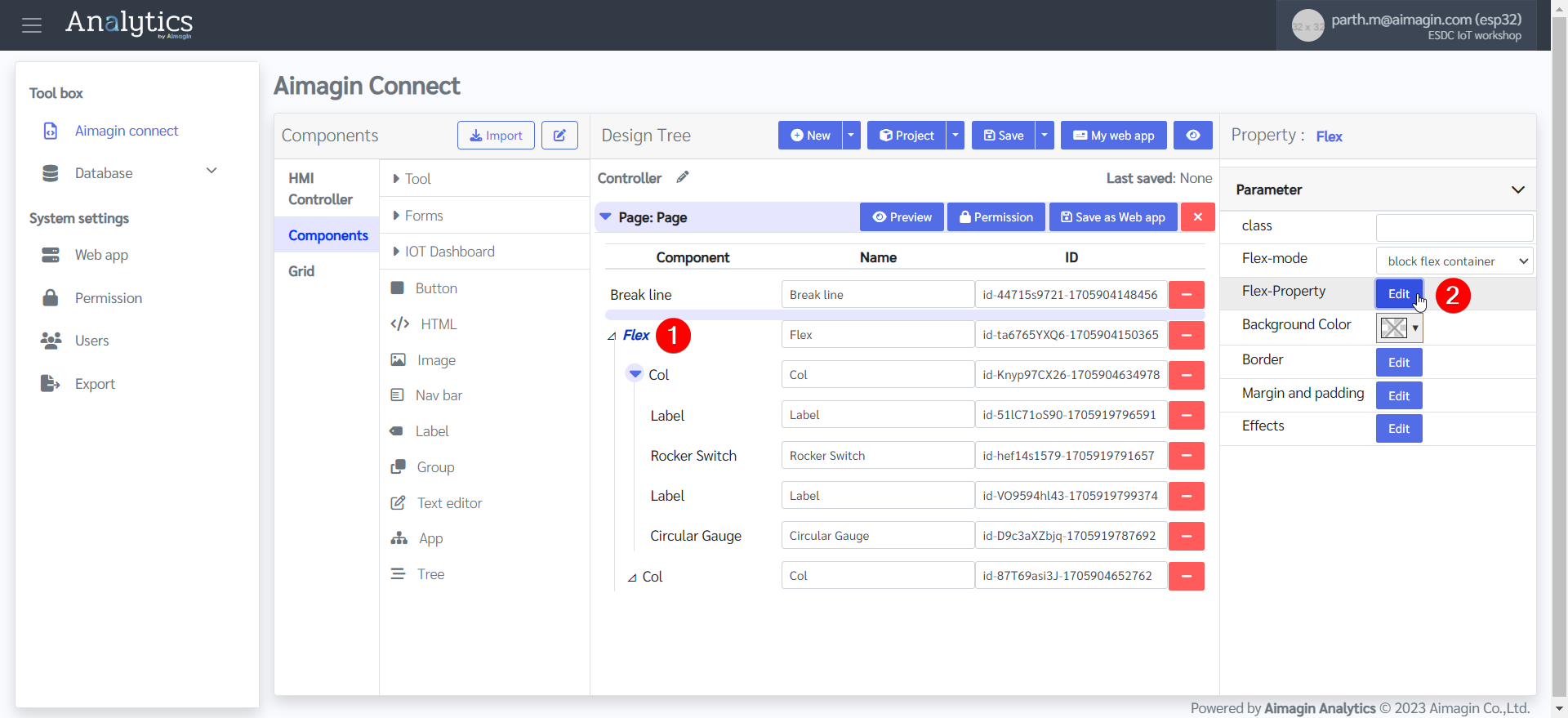
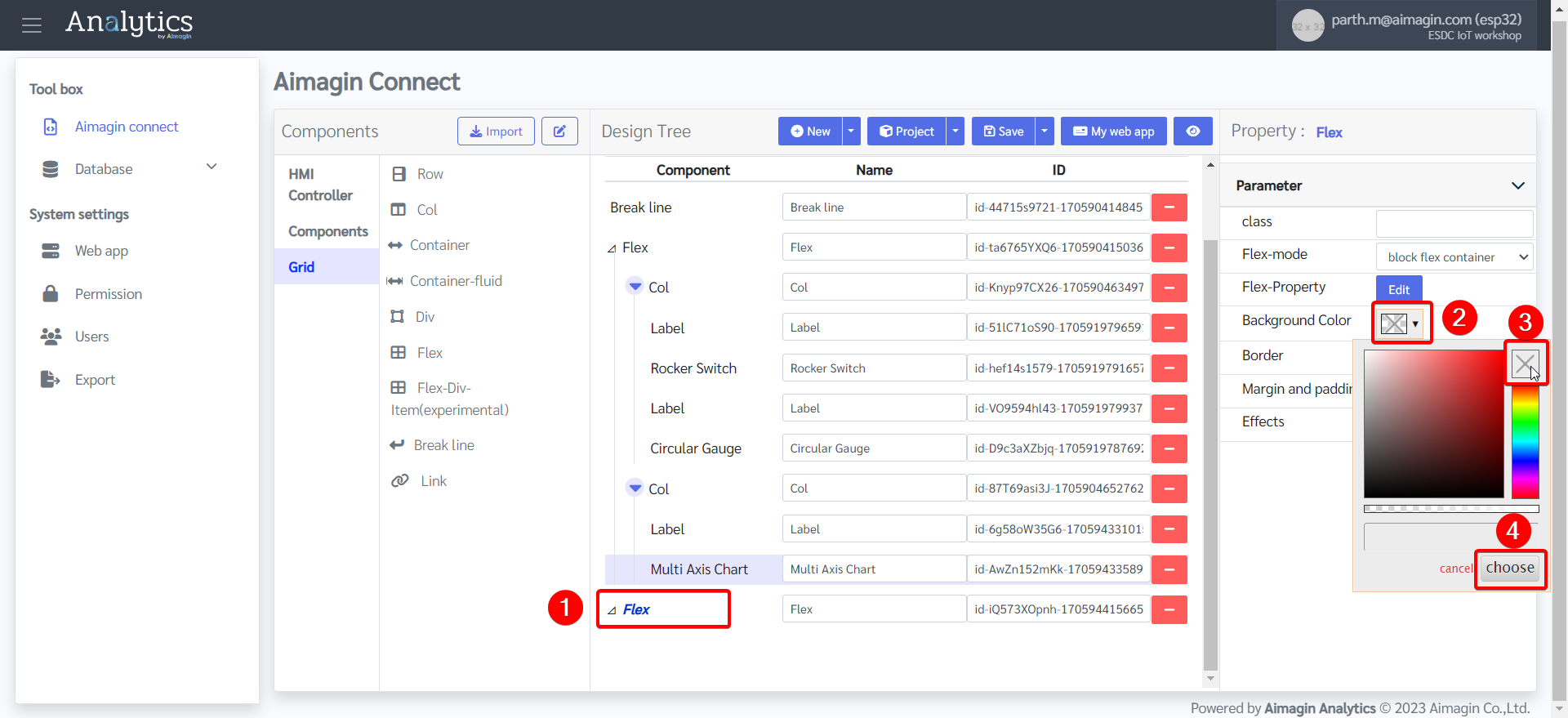
8.Add a Flex and change the background color
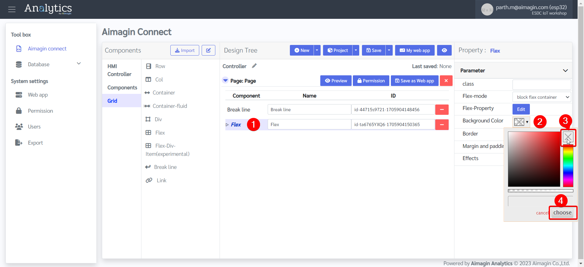
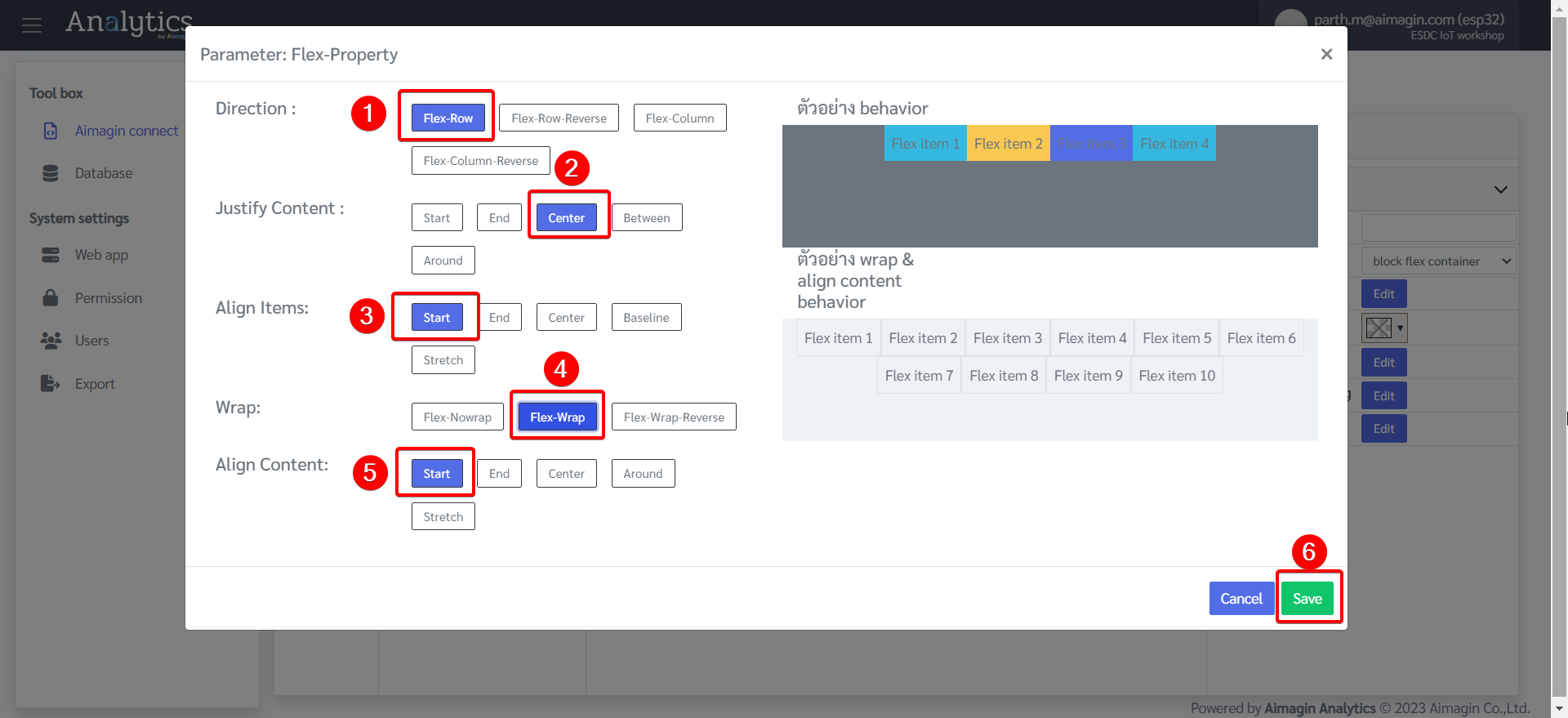
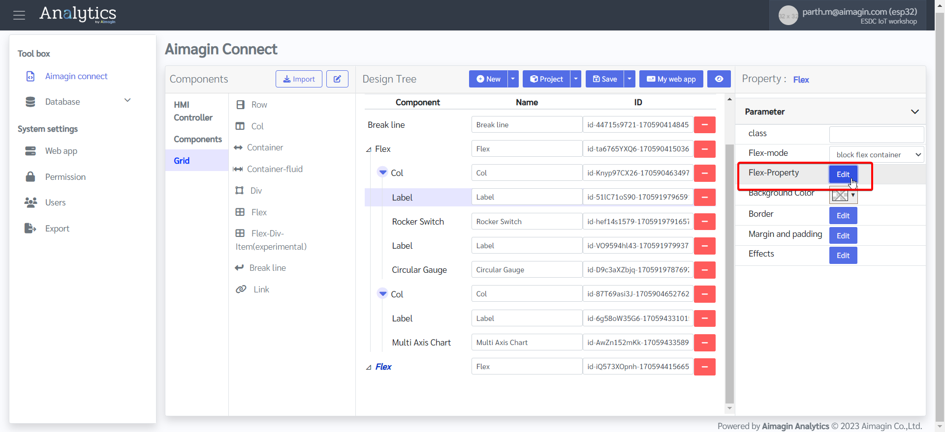
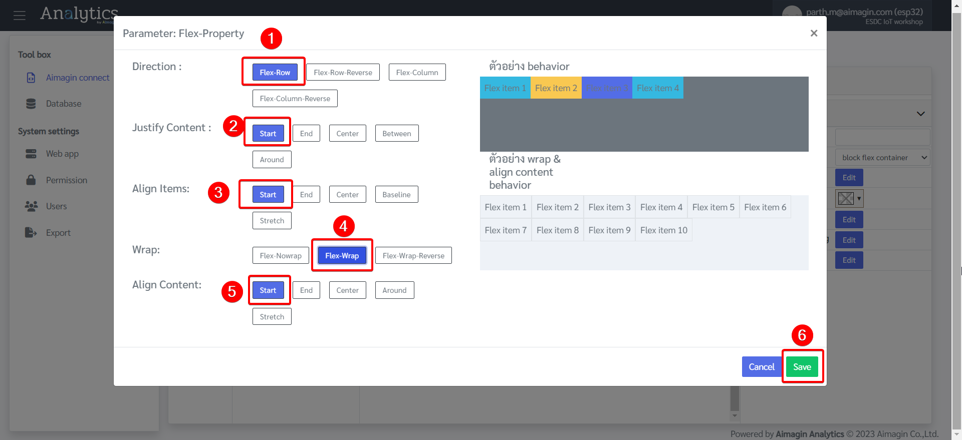
9.Change the Flex Property
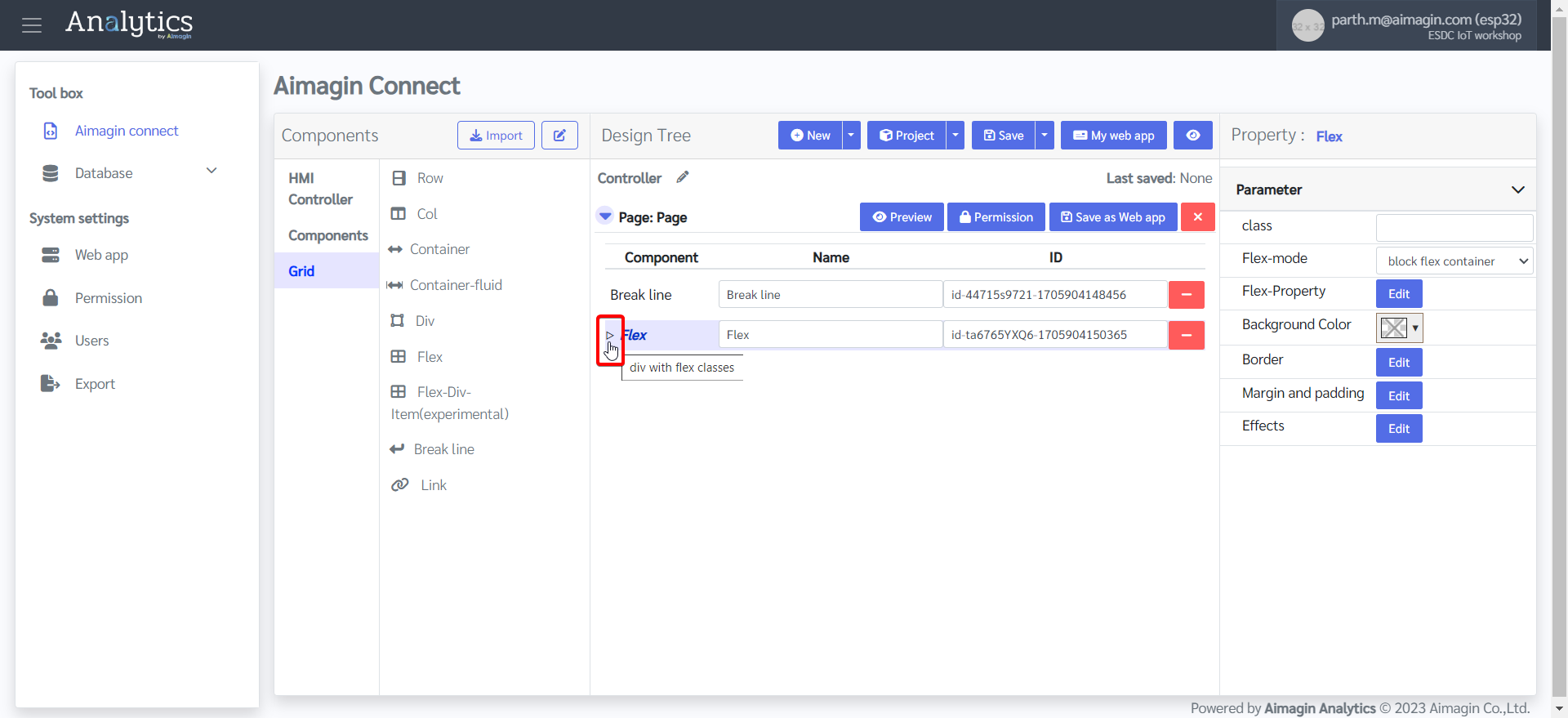
10.Expand the flex to add components under this flex
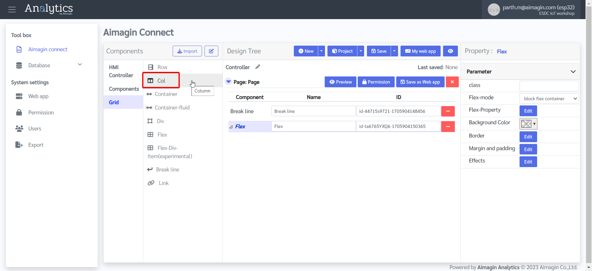
11. Add two columns under this flex
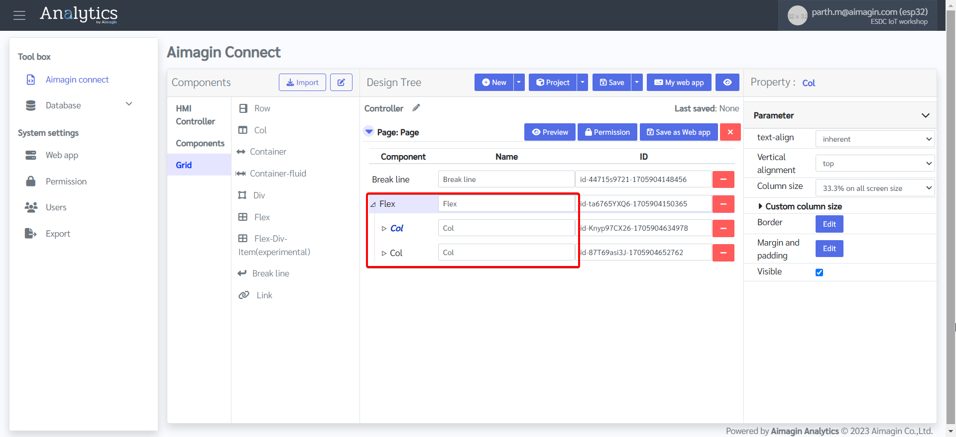
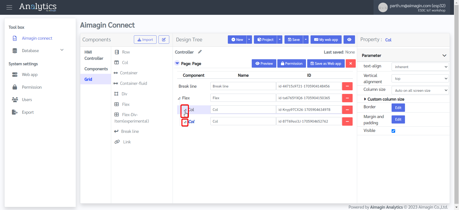
12. Expand both columns
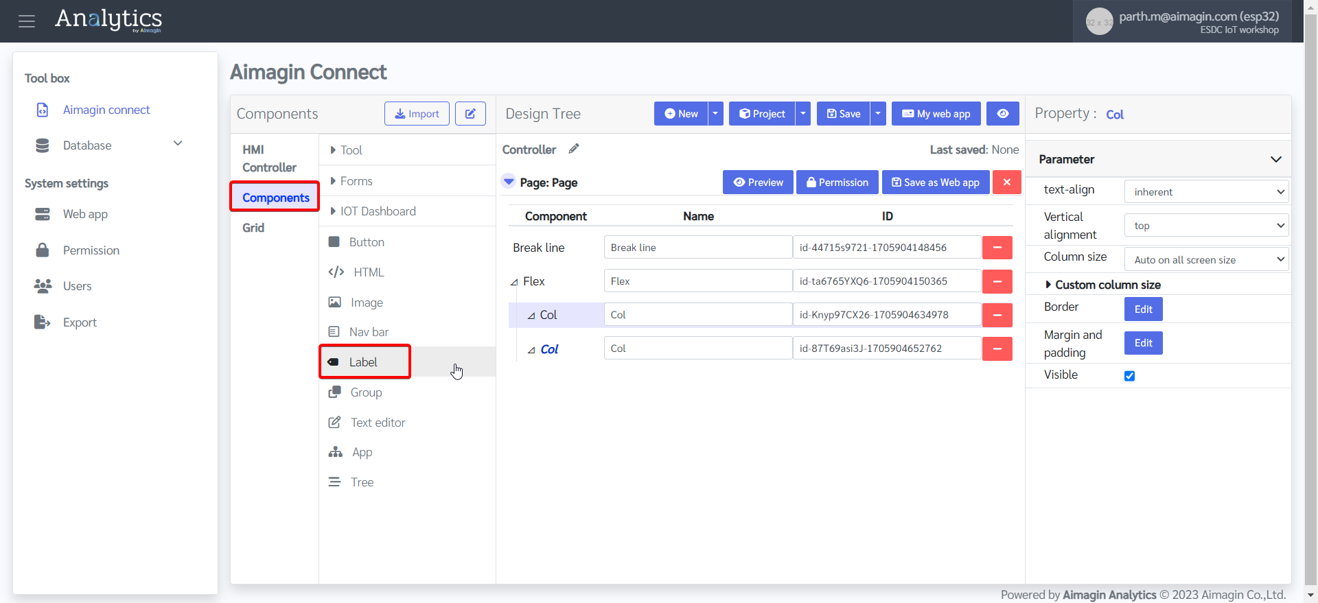
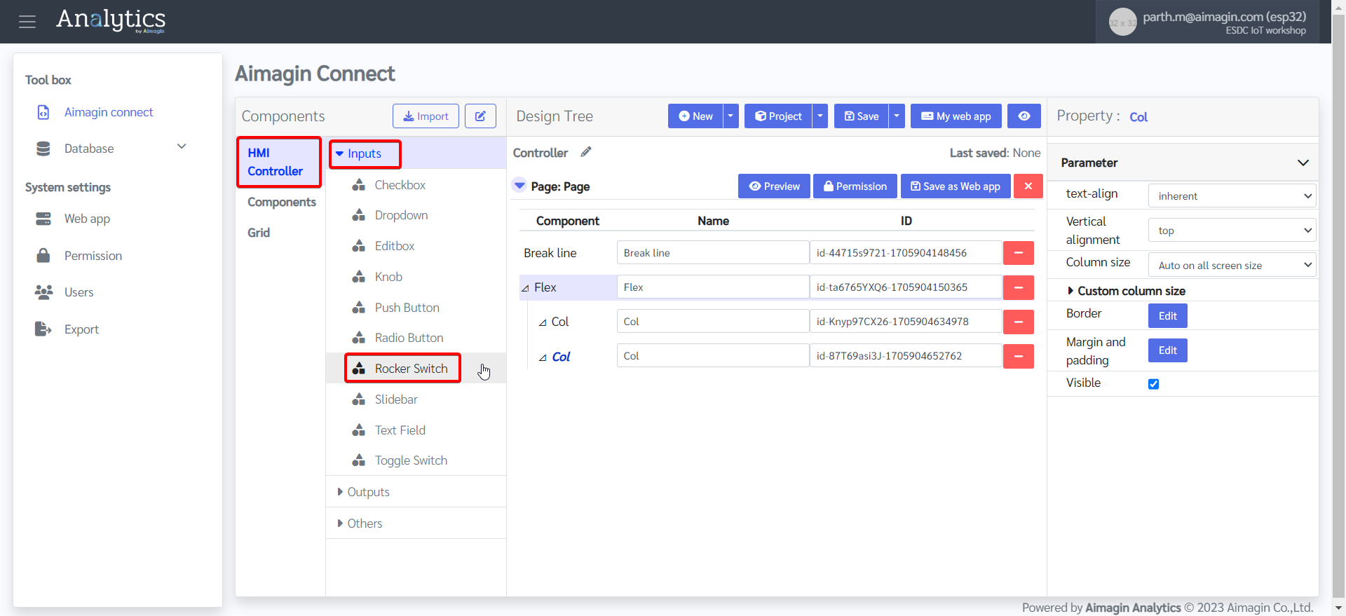
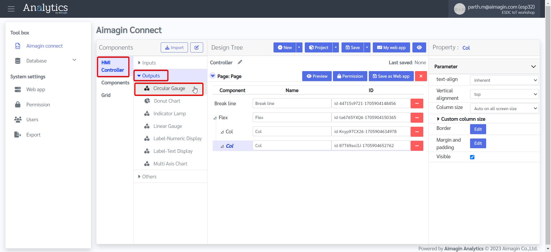
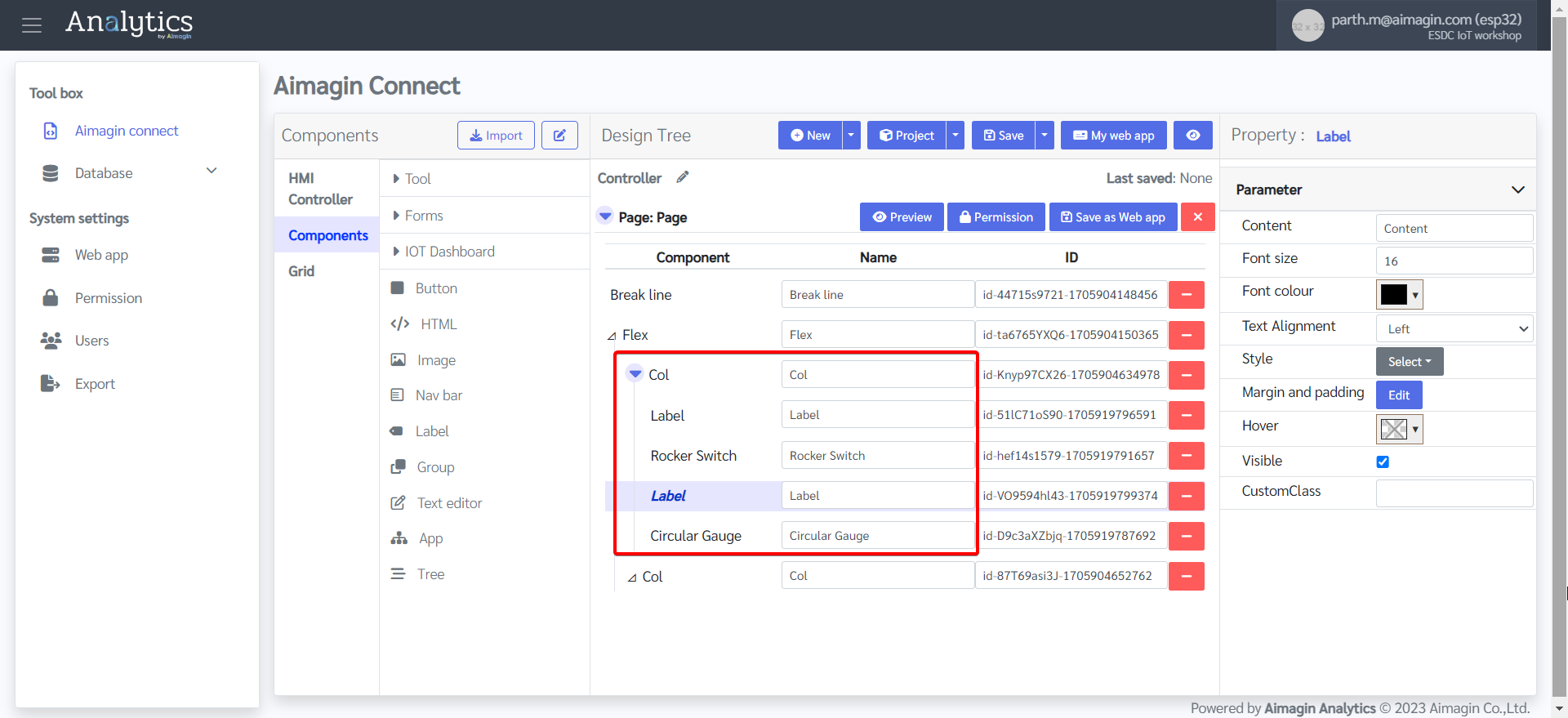
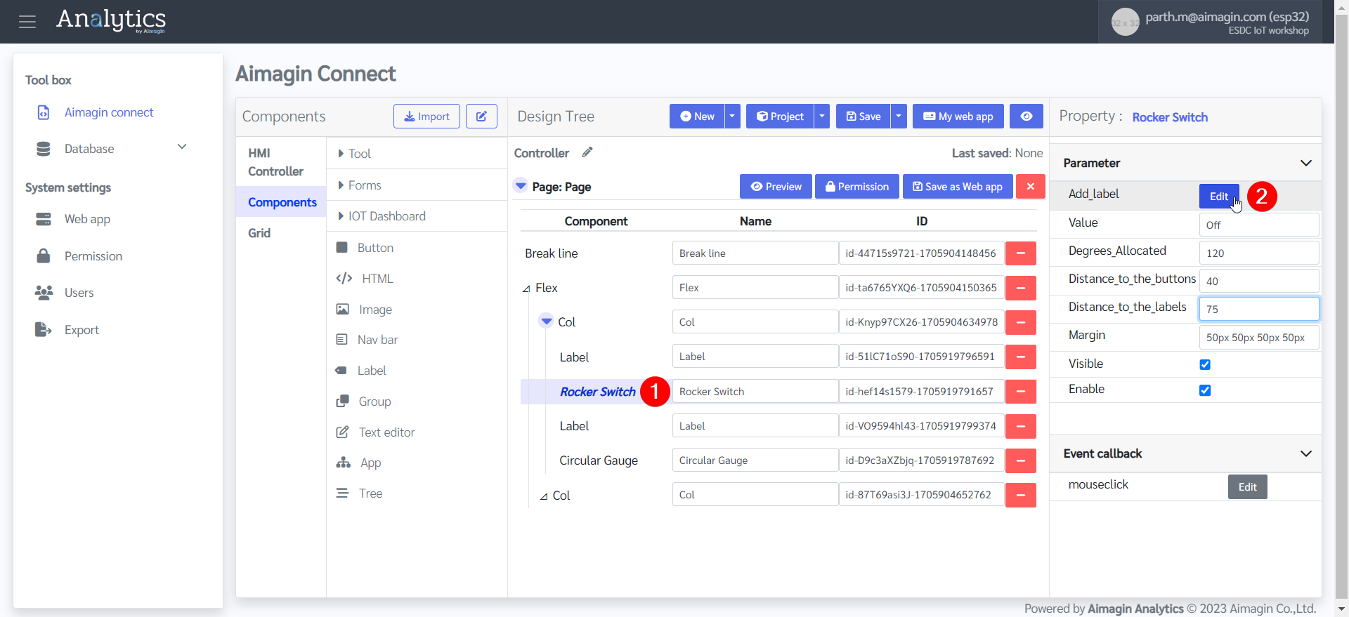
13. Drag and drop two Labels, a Rocker Switch, and a Circular Gauge under the first column.
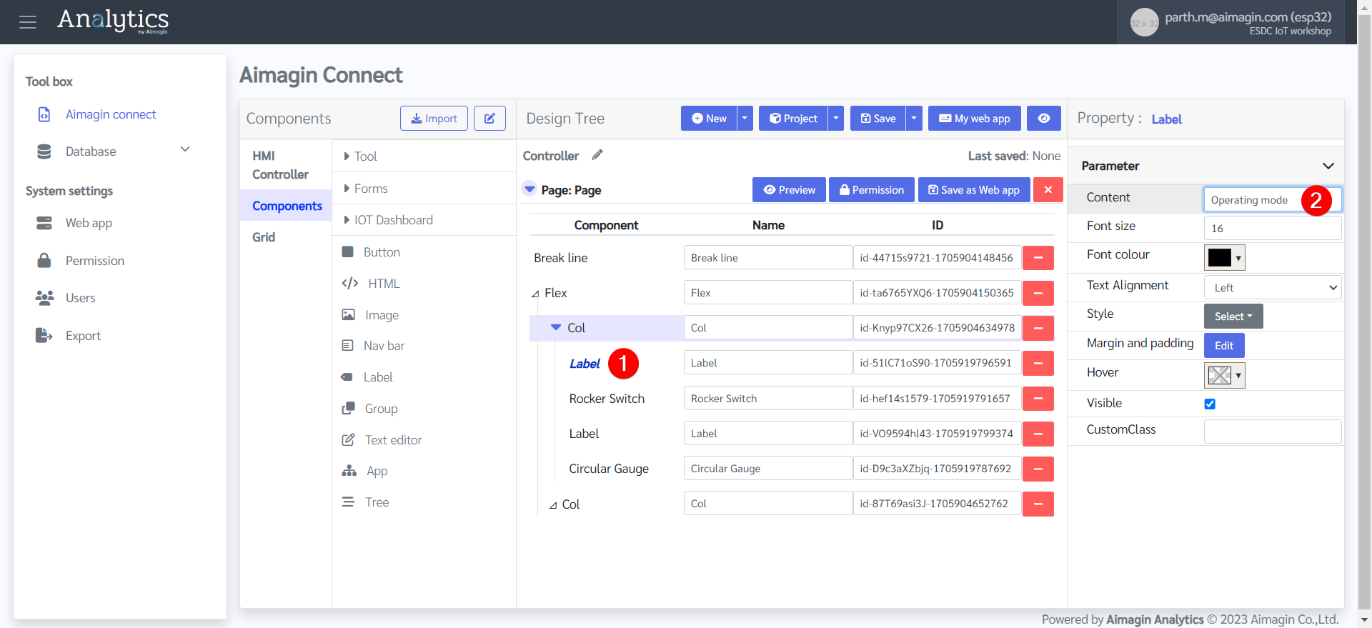
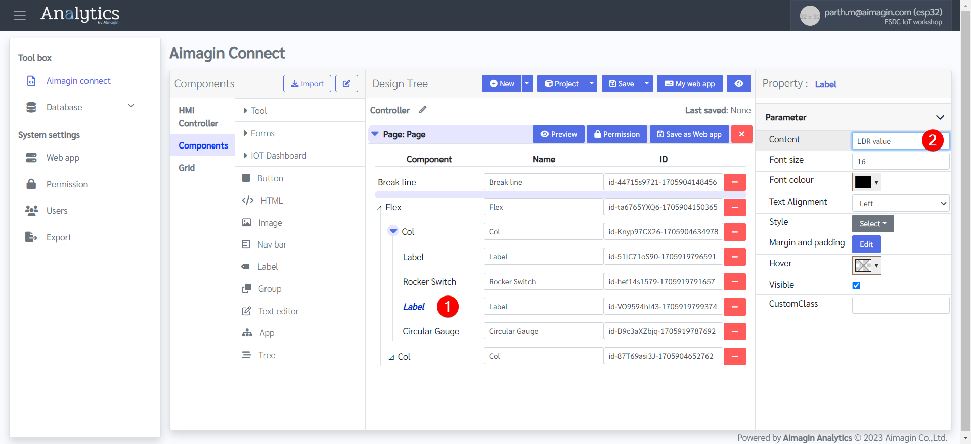
14. Give both labels a name.
15. Save the file and preview (Please do this after every 5-10 steps. If there is a problem with your internet connection, the server, or you refresh the page, all unsaved work will be lost). Previewing the file will also help you see your progress.
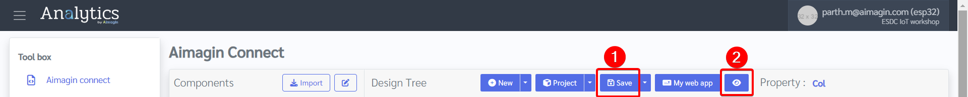
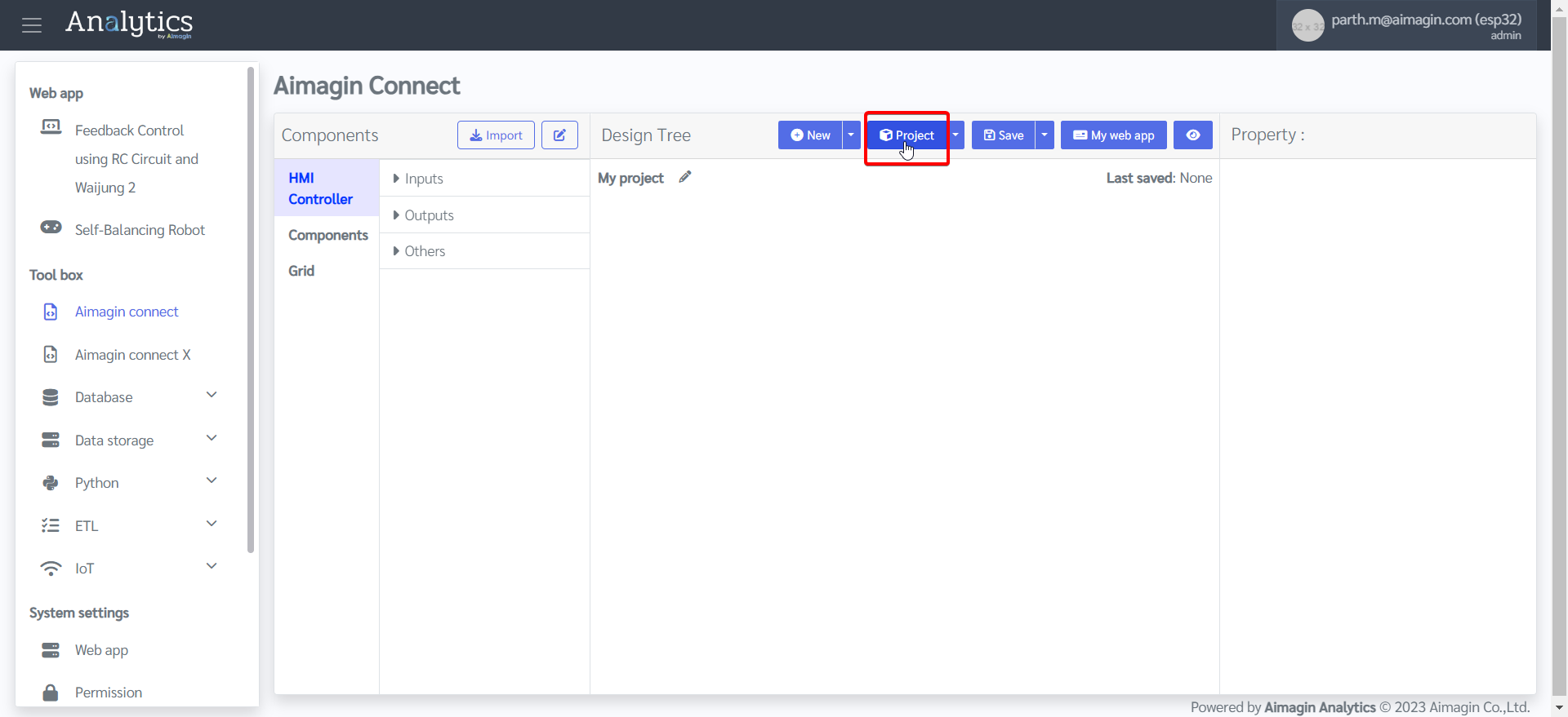
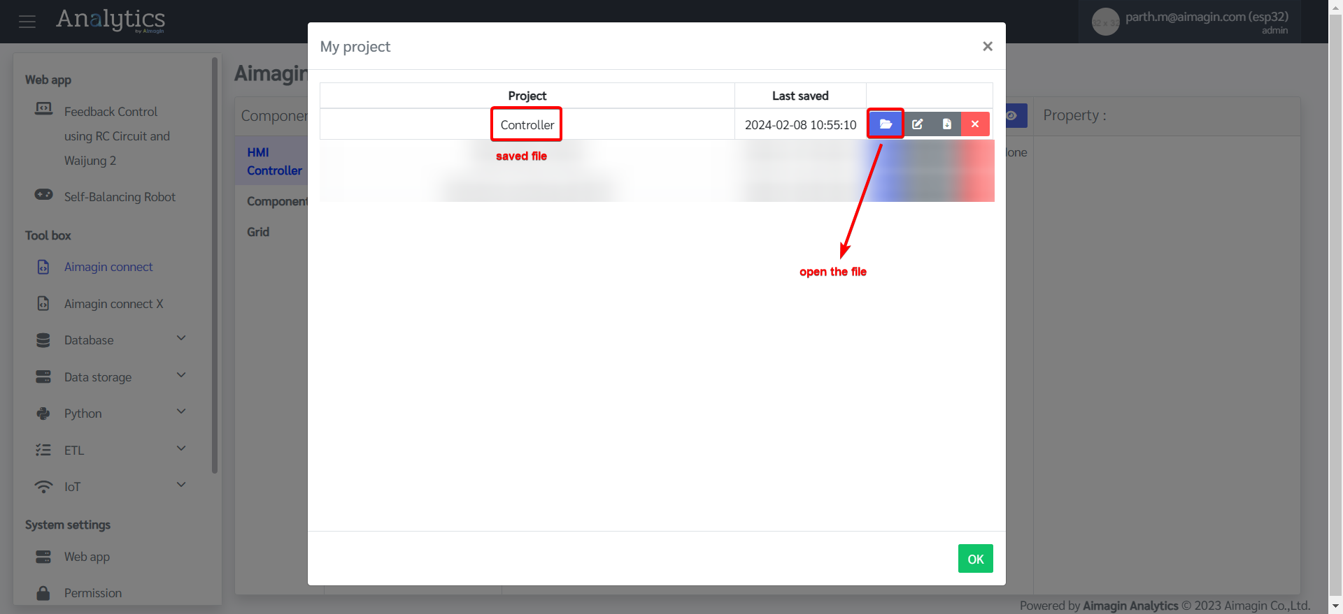
16. You can view the saved file under Project. If there is ever a problem with internet connection / server / page refreshing, your saved file will be found under Project and you can open it and continue your work.
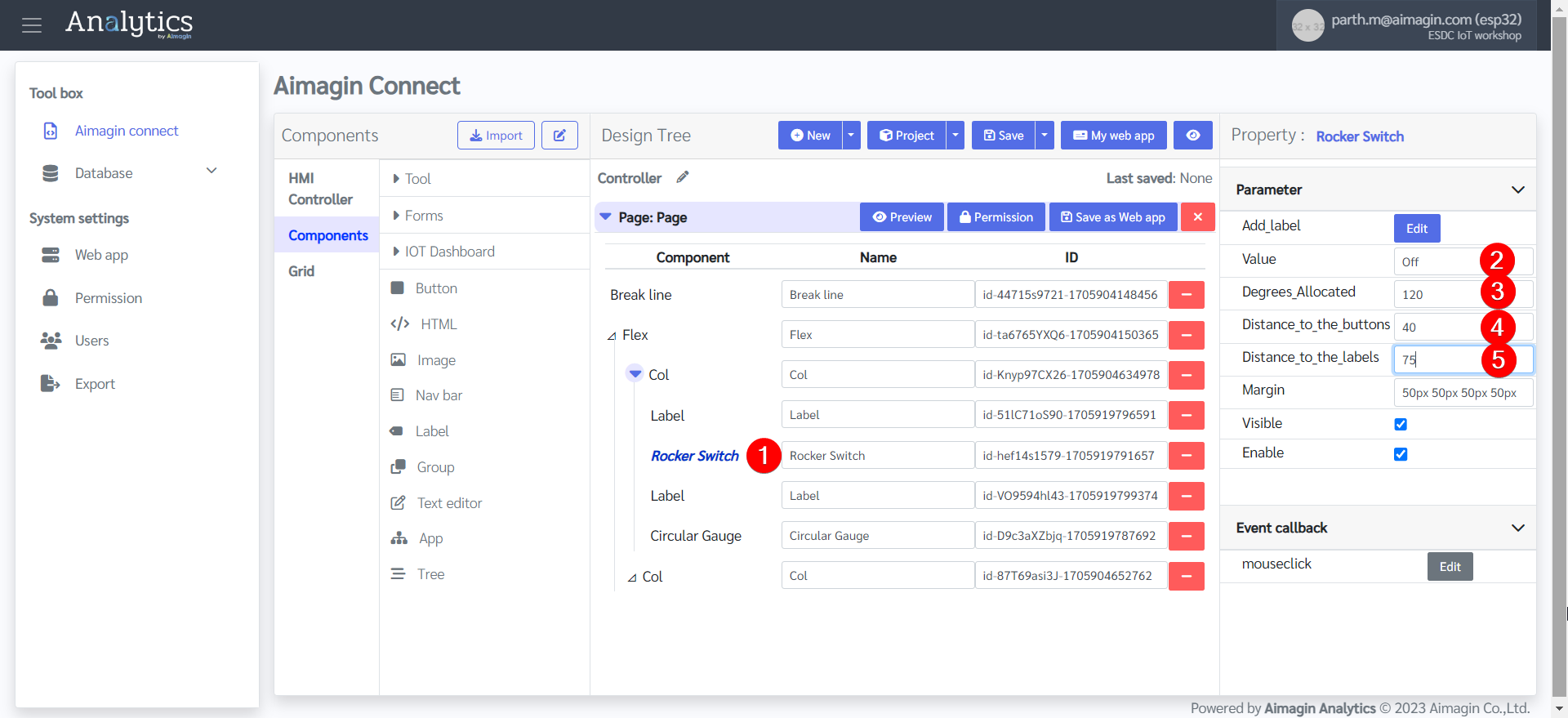
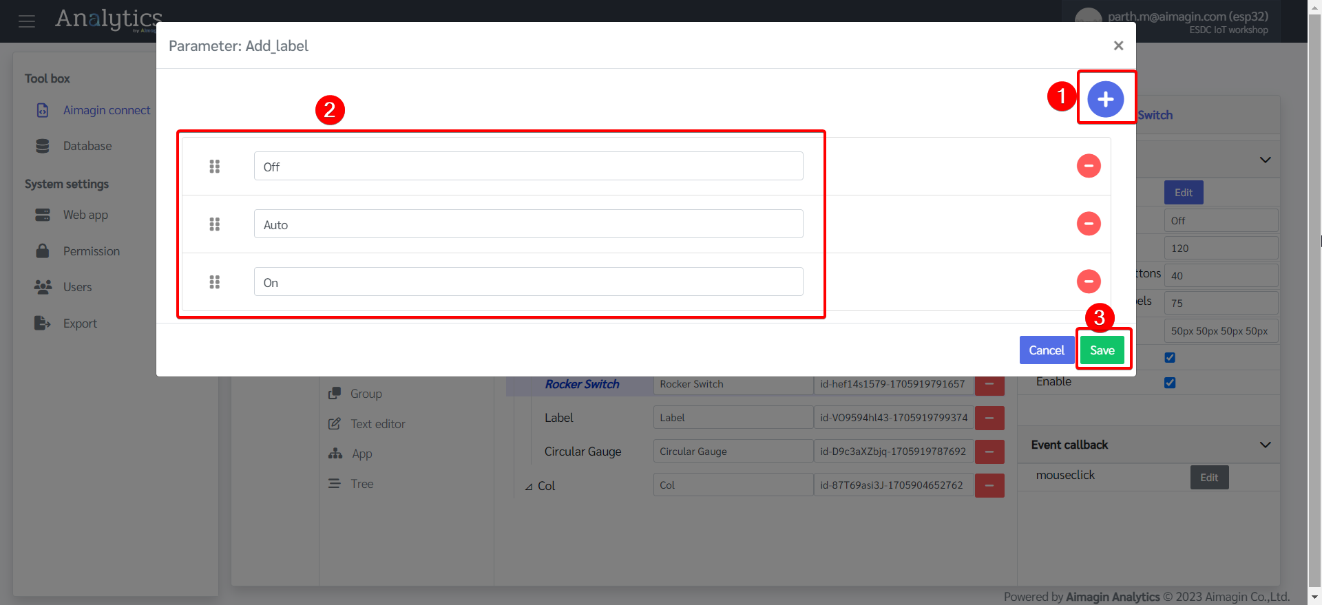
17.Configure the Rocker Switch.
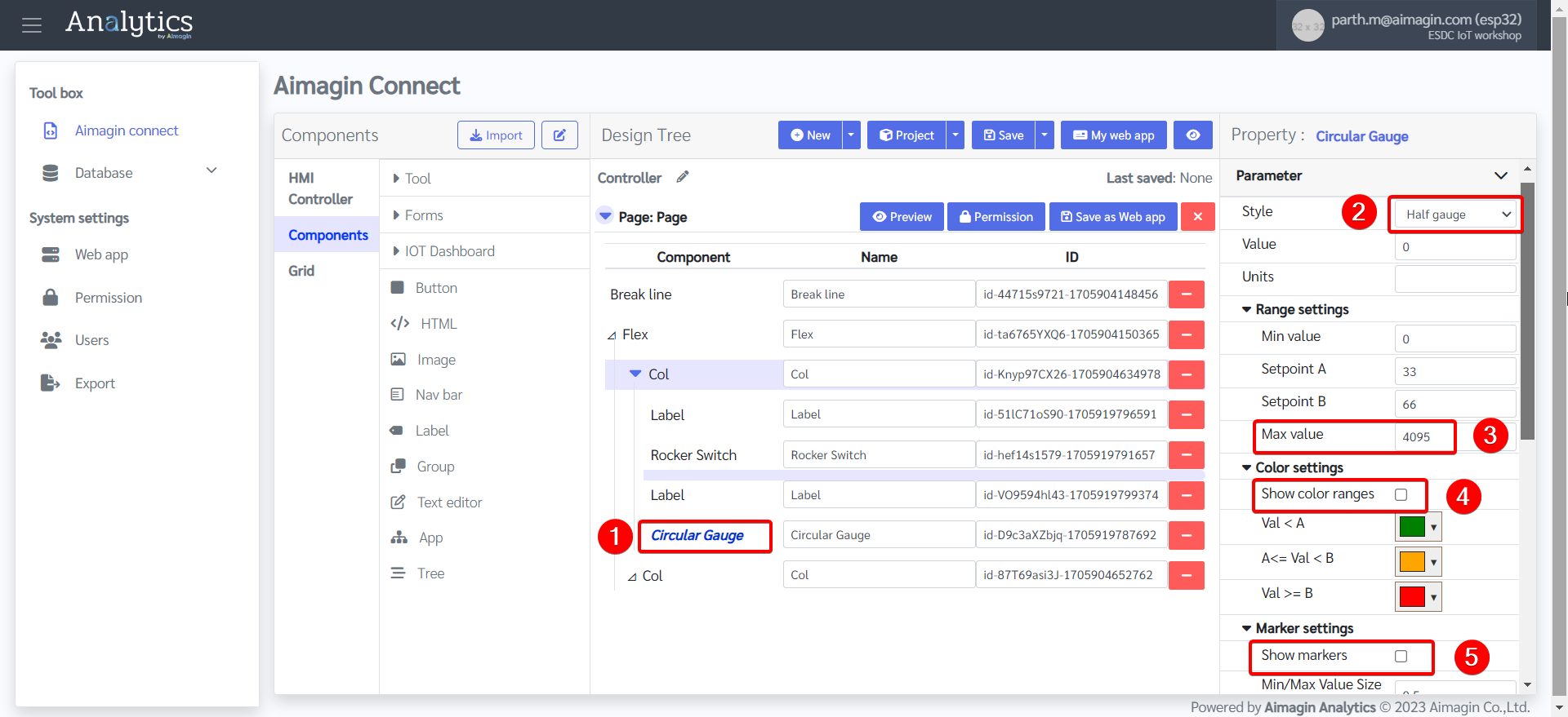
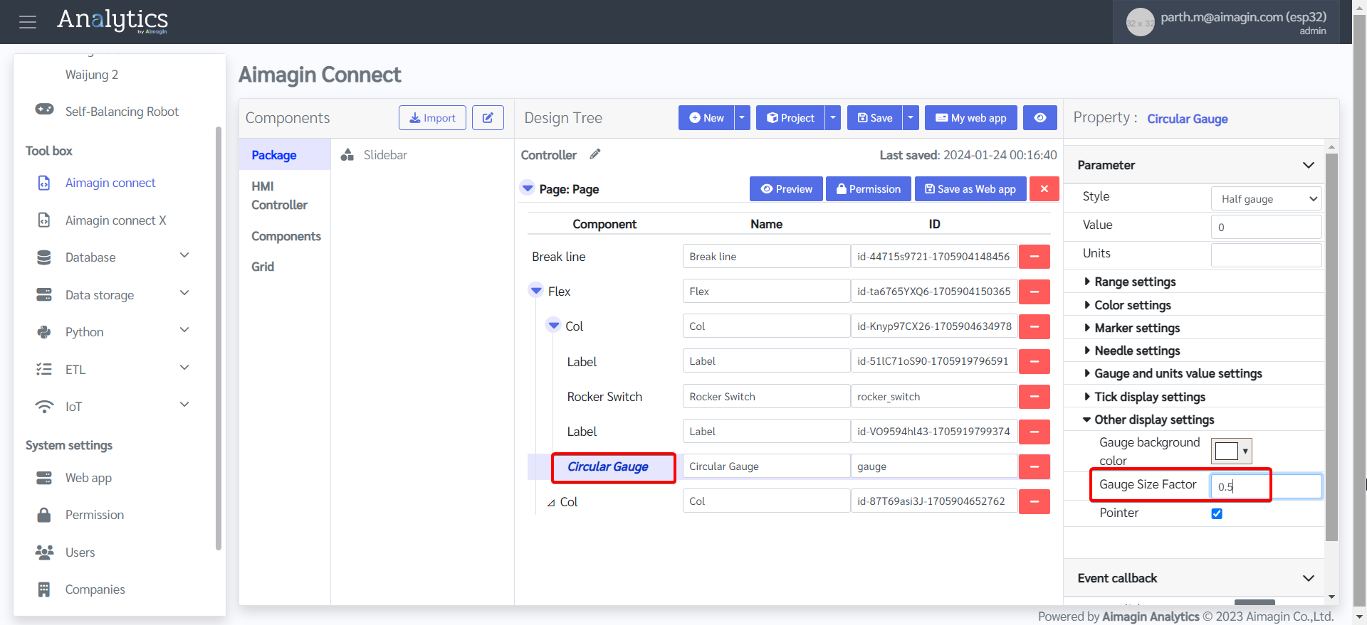
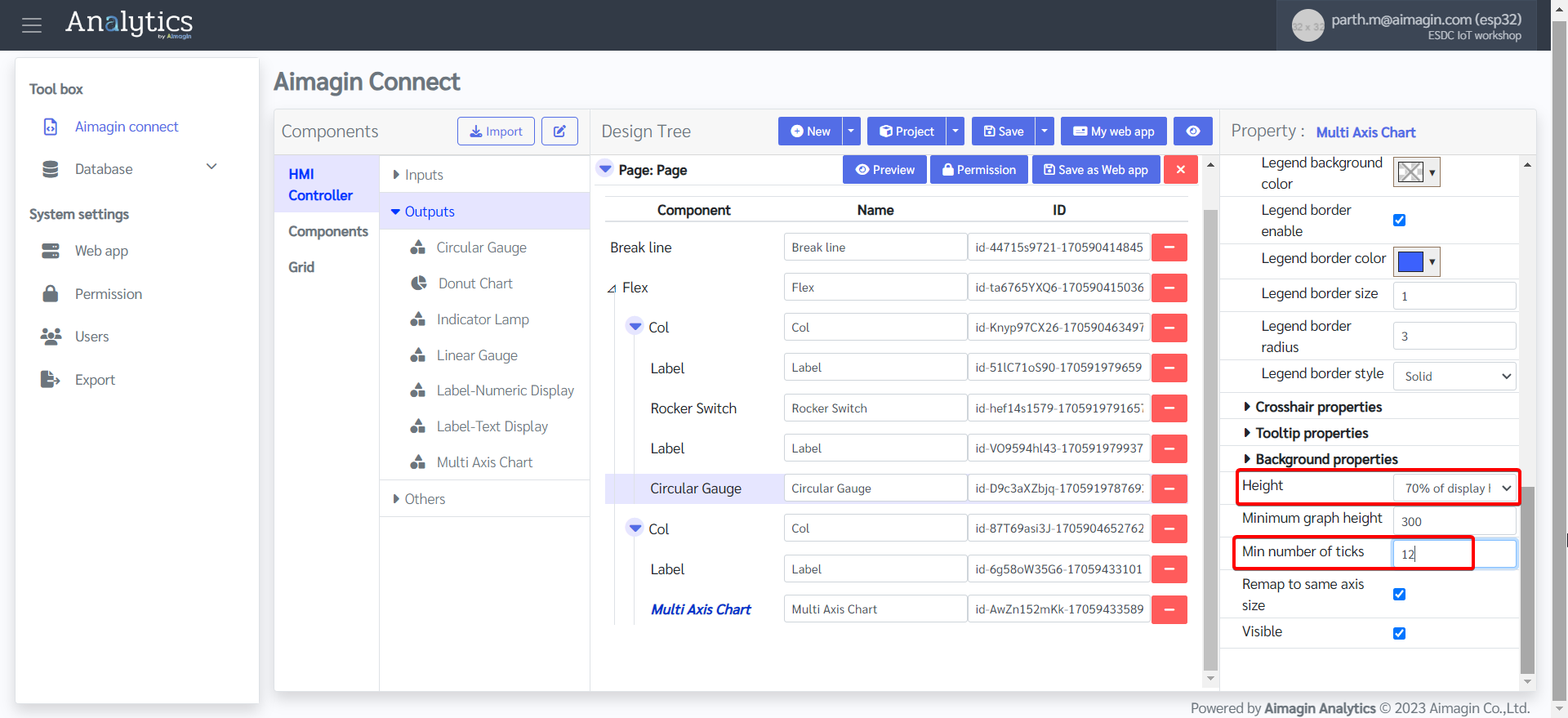
18. Configure the Circular Gauge.
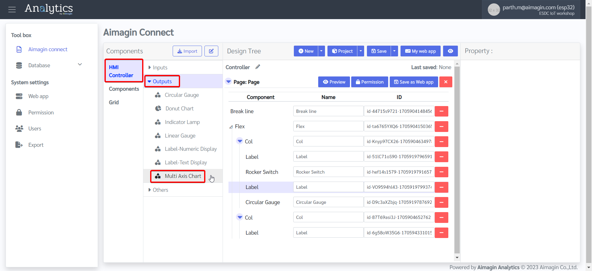
19. Drag and drop a label and Multi Axis Chart under the second column.
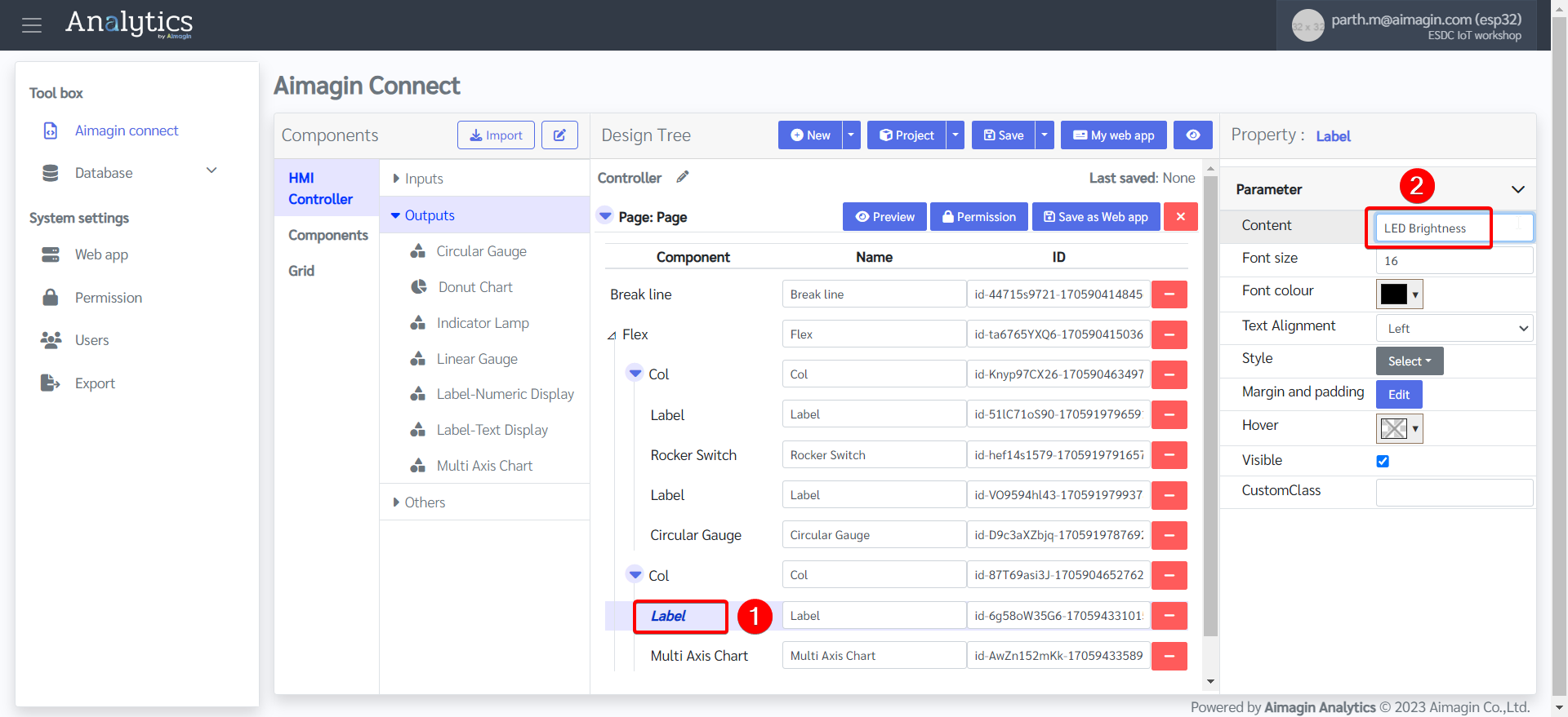
20. Change Label name.
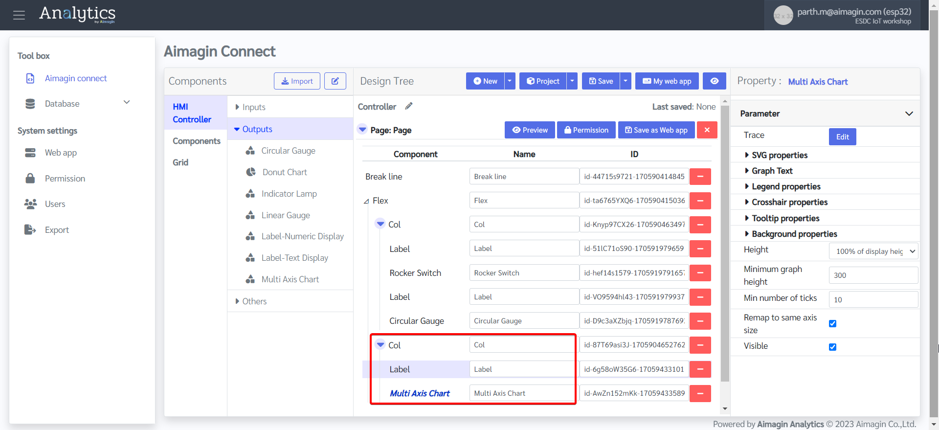
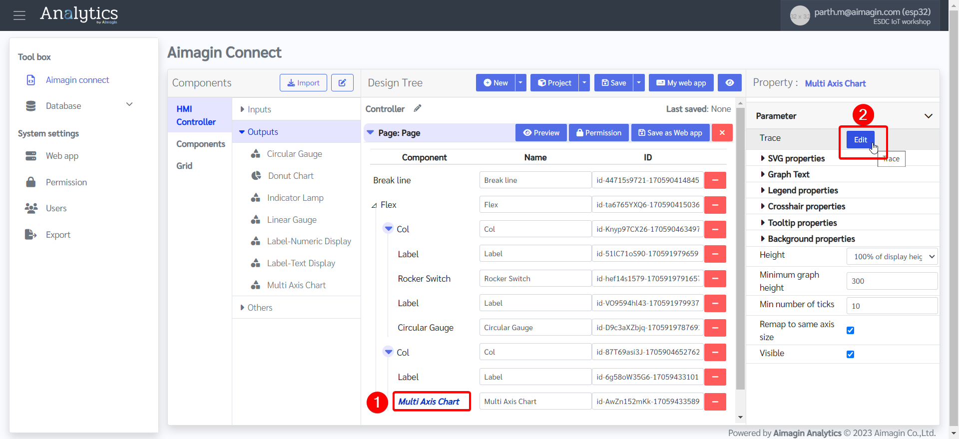
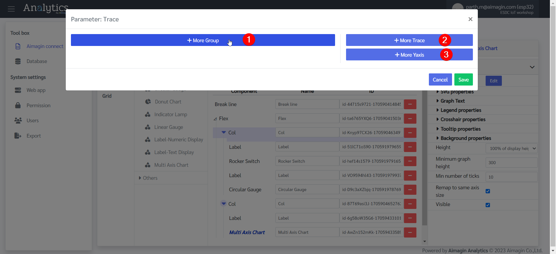
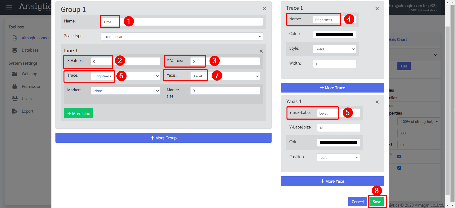
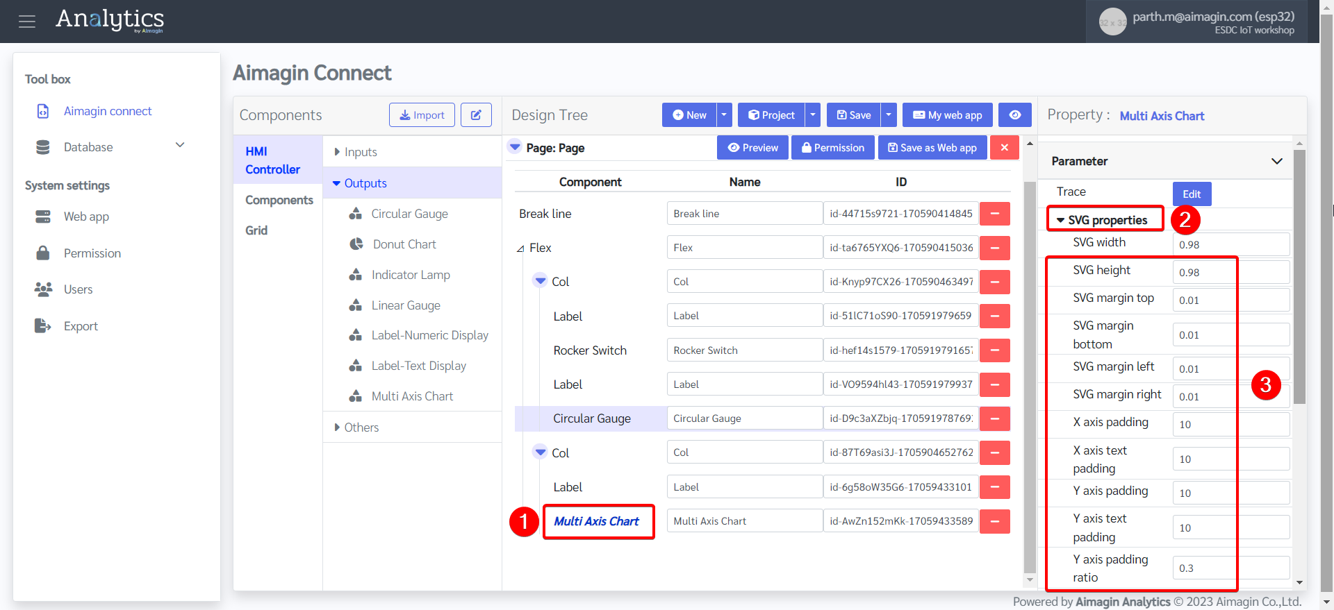
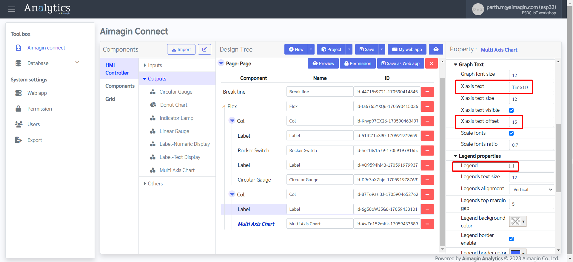
21. Configure the Multi Axis Chart.
22. Add another Flex, change the background color, and edit the Flex Property.
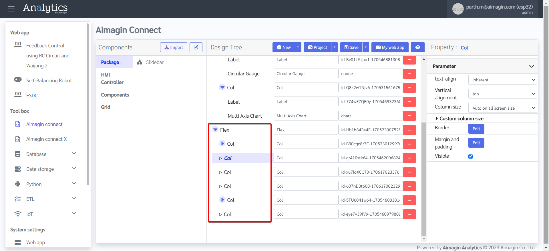
23. Add six columns under this Flex.
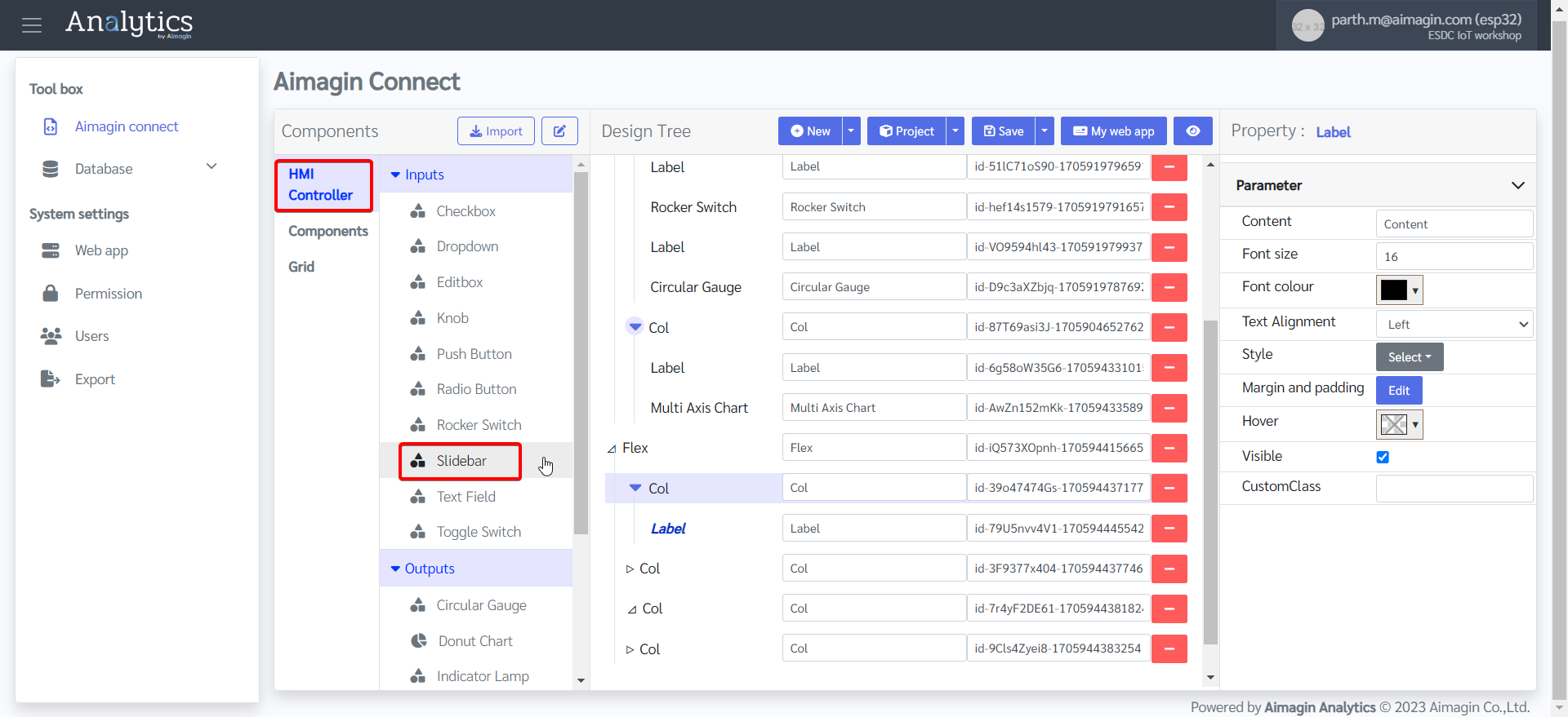
24. Under the first and fifth columns, add a Label and a Slidebar component. Leave the other columns empty.
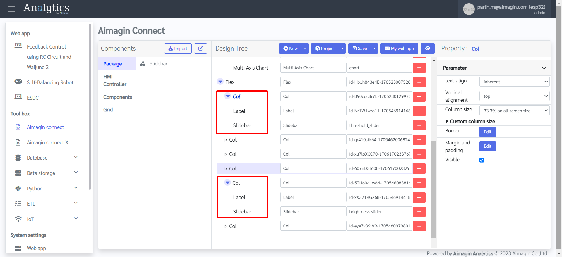
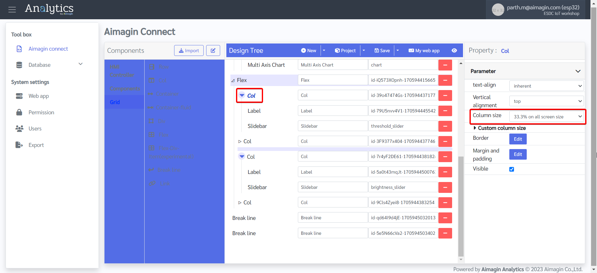
25. Change the column size of the first and fifth columns to 33.3% on all screen size. This will help with sizing and spacing of the Slidebars in addition to the appropriate alignment of the webpage.

26. Change the label names.
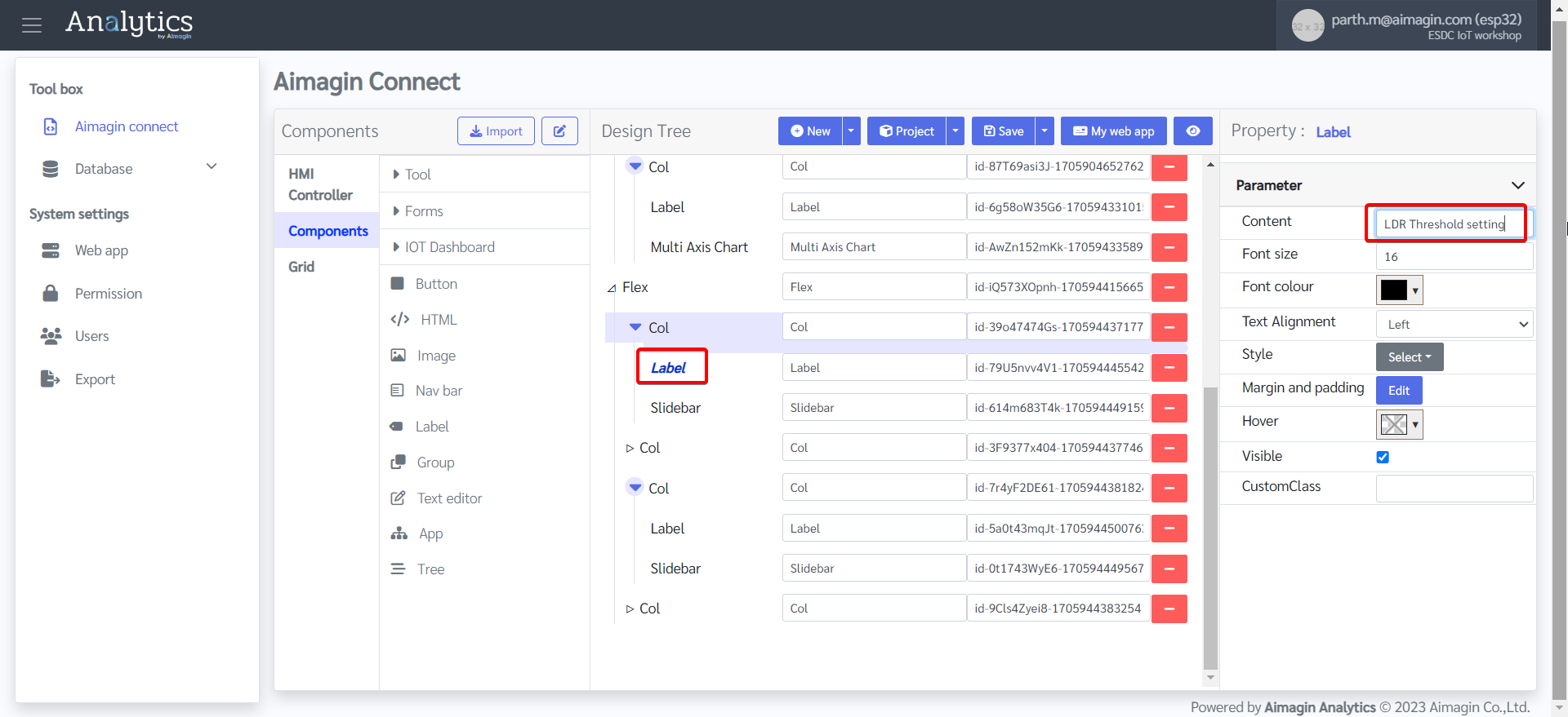
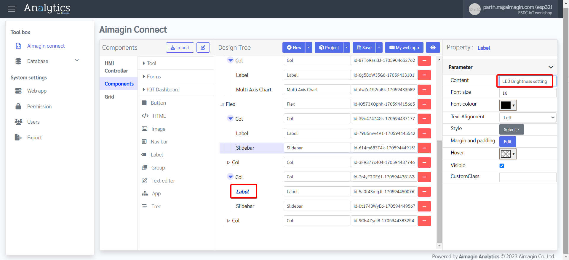
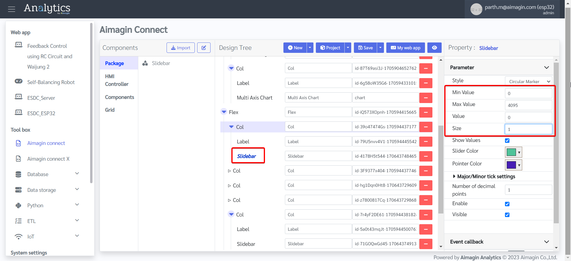
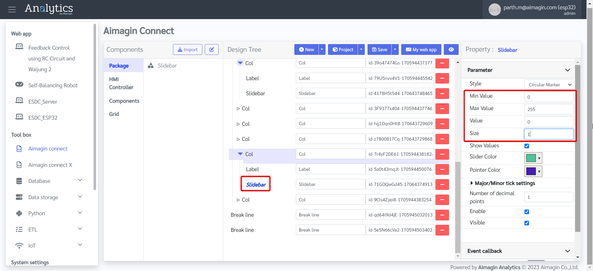
27. Configure the two Slidebars.
28. Add two Break lines after the Flex.
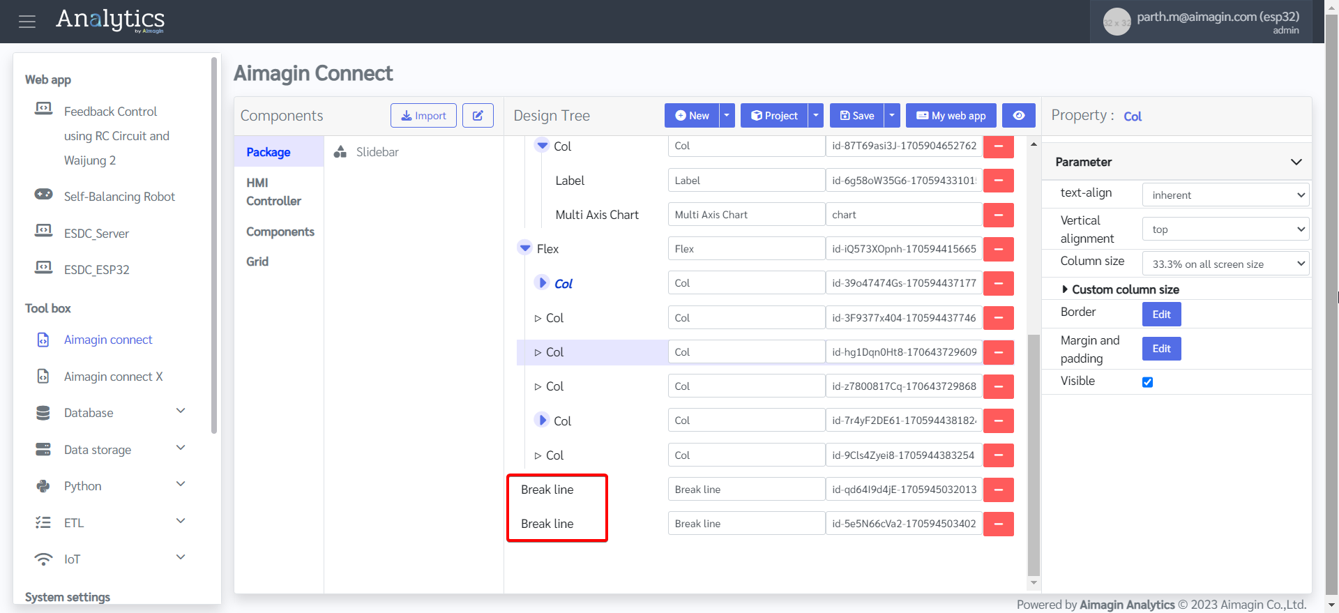
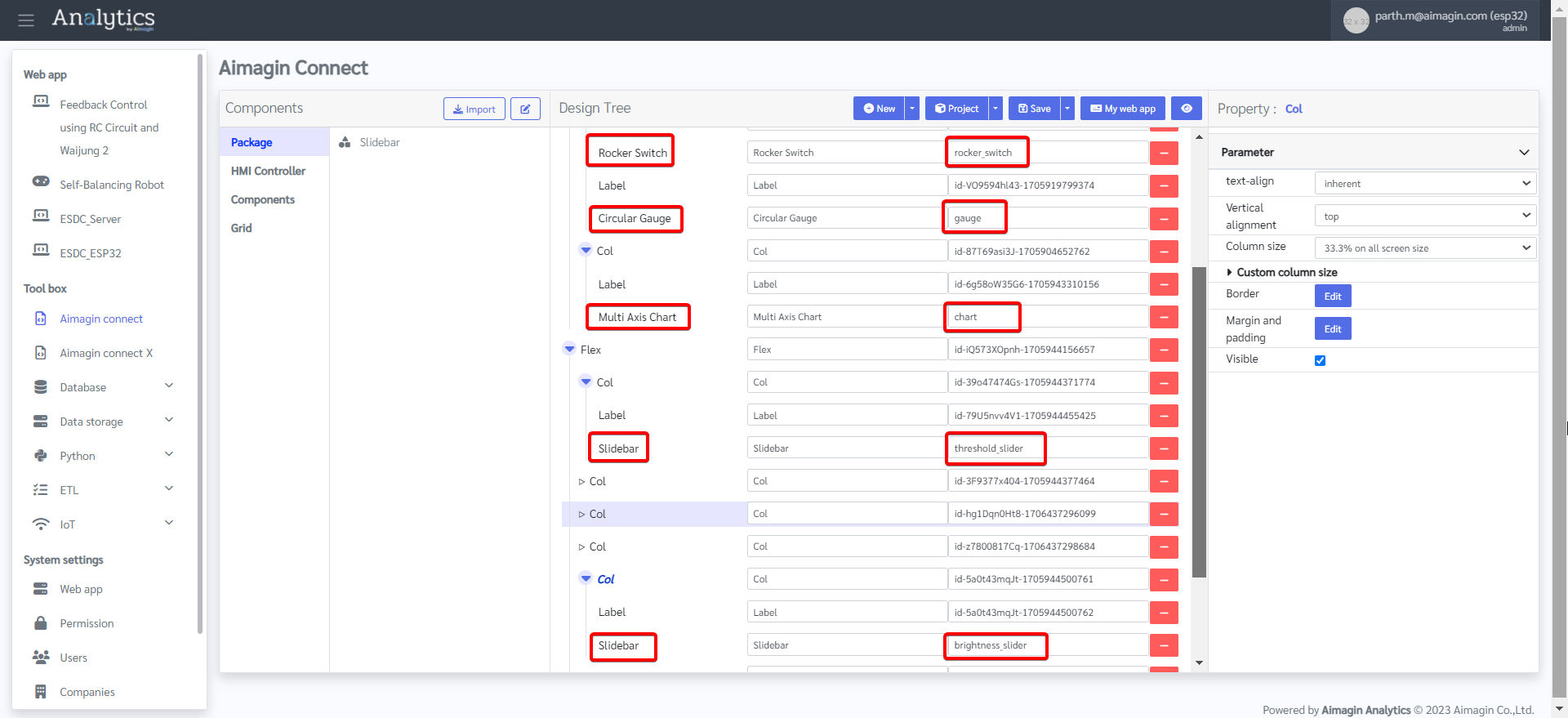
29. Change ID of some components.
Slidebar 1 ID: threshold_slider
Slidebar 2 ID: brightness_slider
Multi Axis Chart ID: chart
Circular Gauge ID: gauge
Rocker Switch ID: rocker_switch
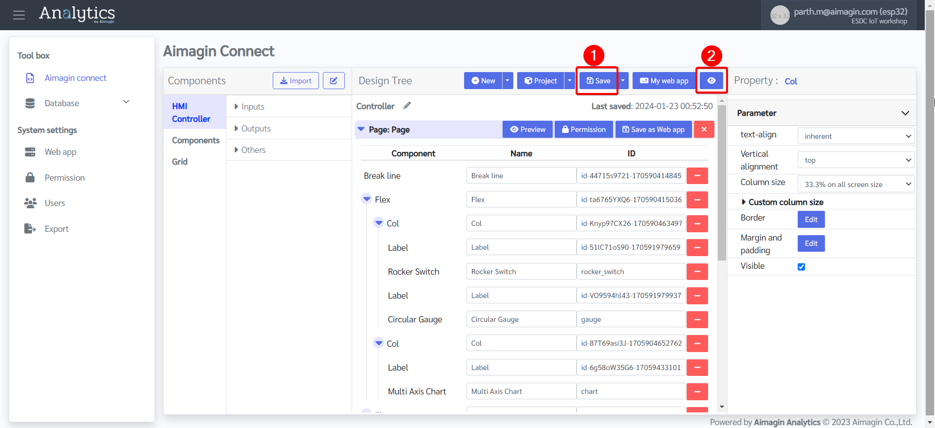
30. Save the file and preview.
Design of the web application is complete. Now the next step is to make it functional.
PART 2: ADD FUNCTIONALITY TO WEB APPLICATION
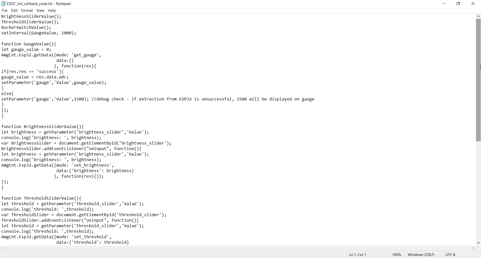
1.Add callback code. Download this file and open it.
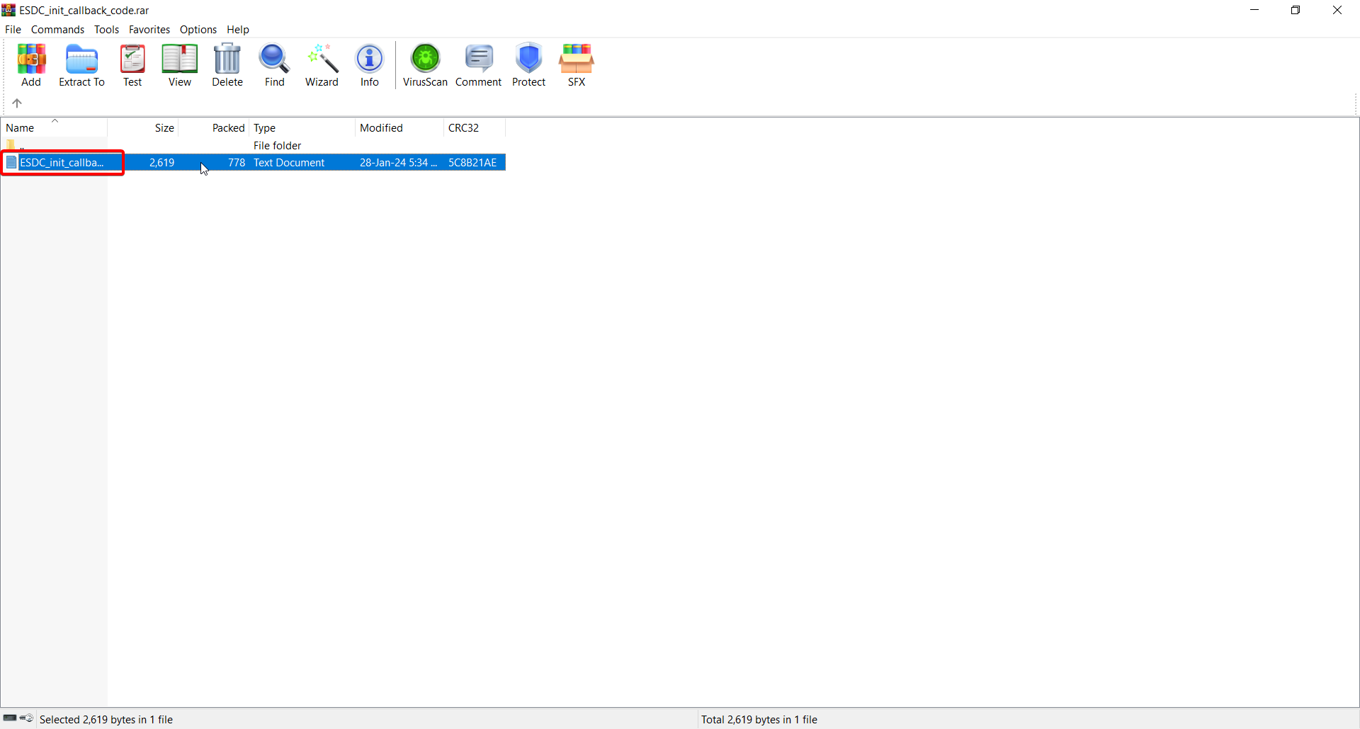
2.Copy the code.
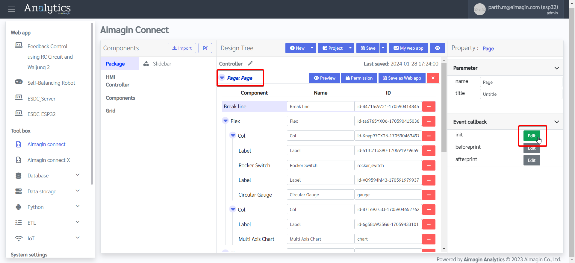
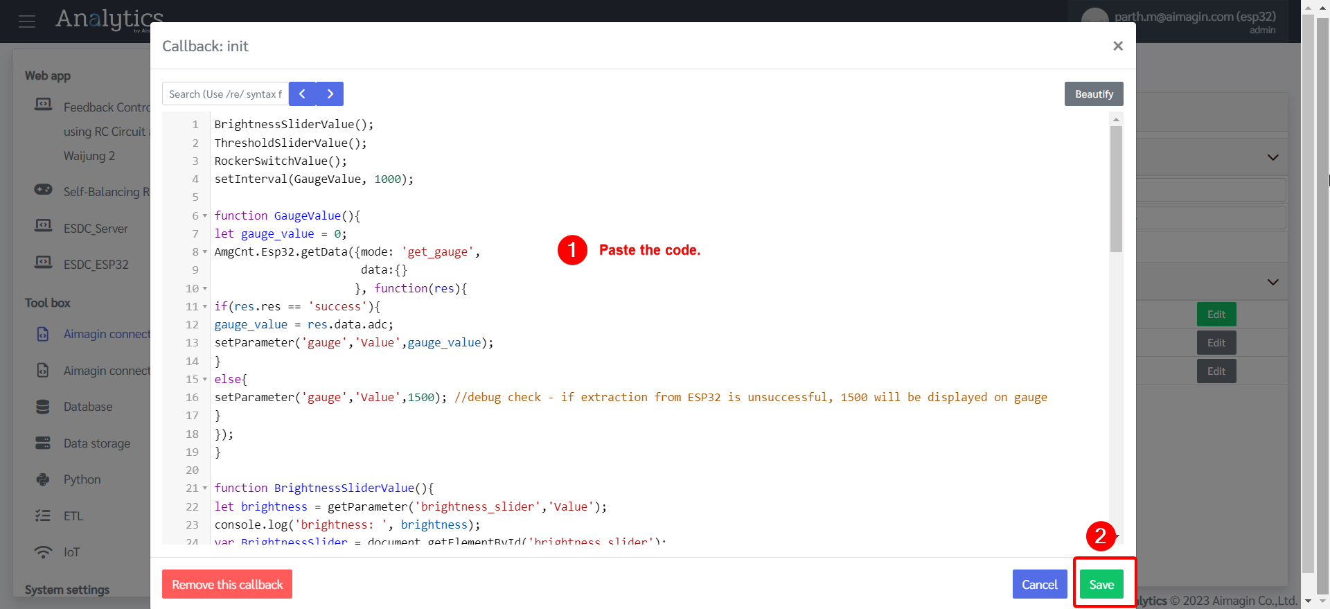
3.Paste the code in the "init" section and save.
4.Give the page a name and save the file.
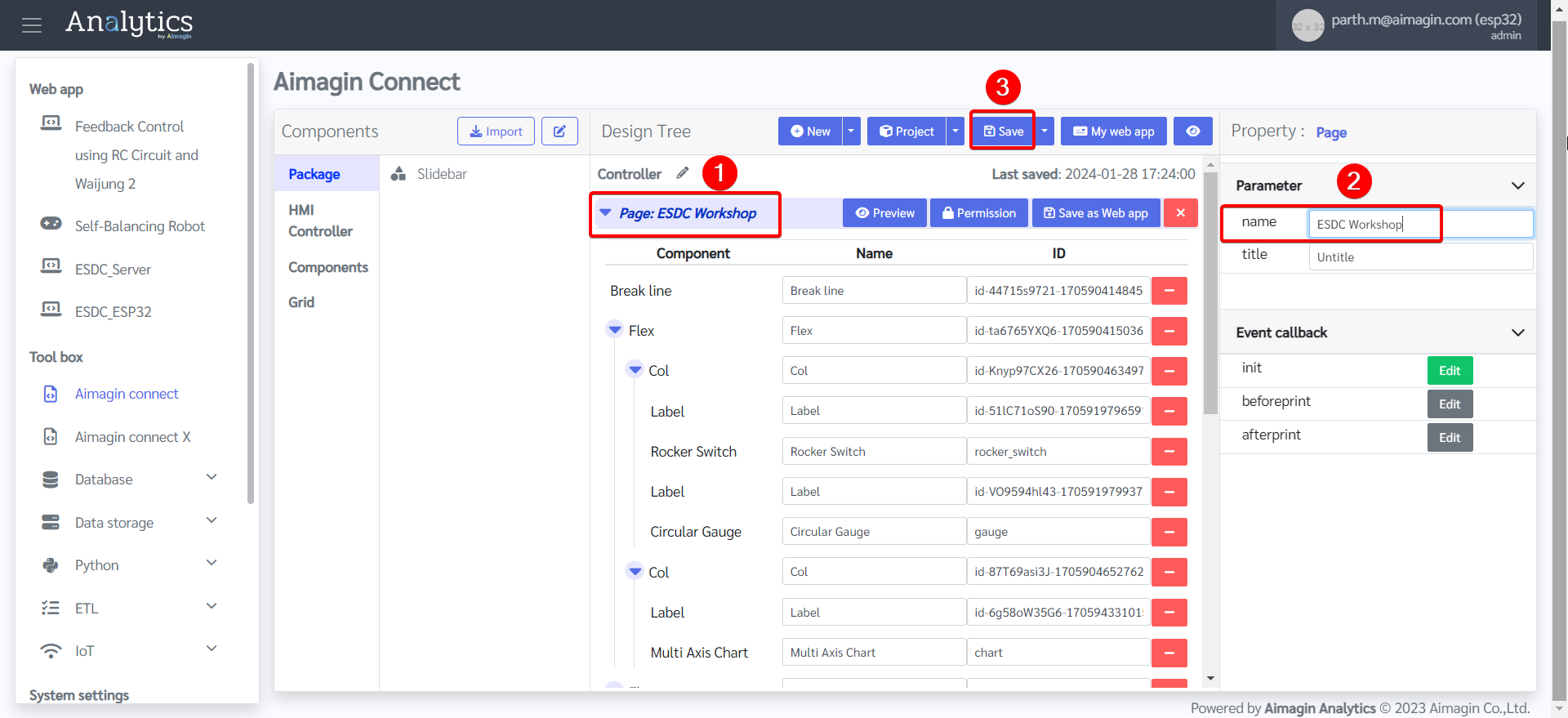
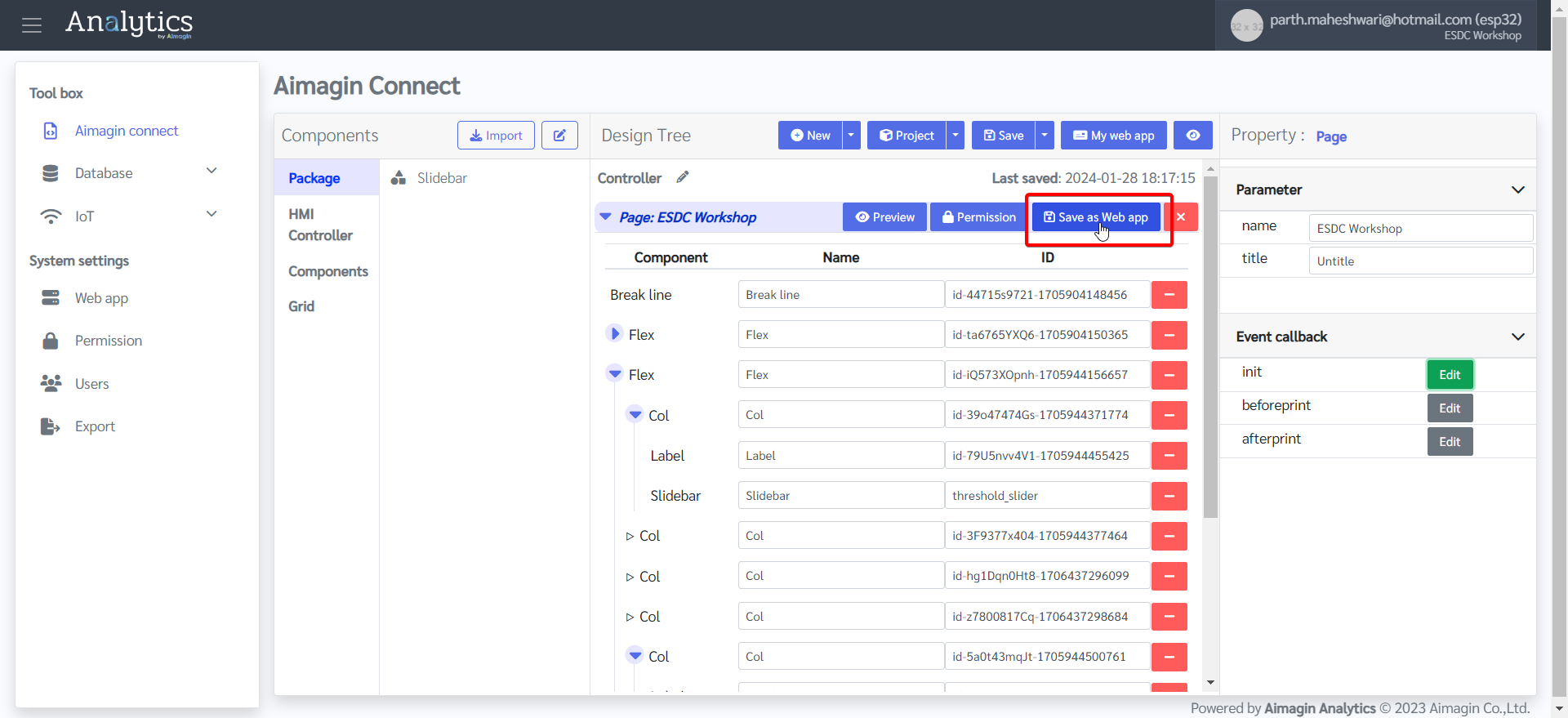
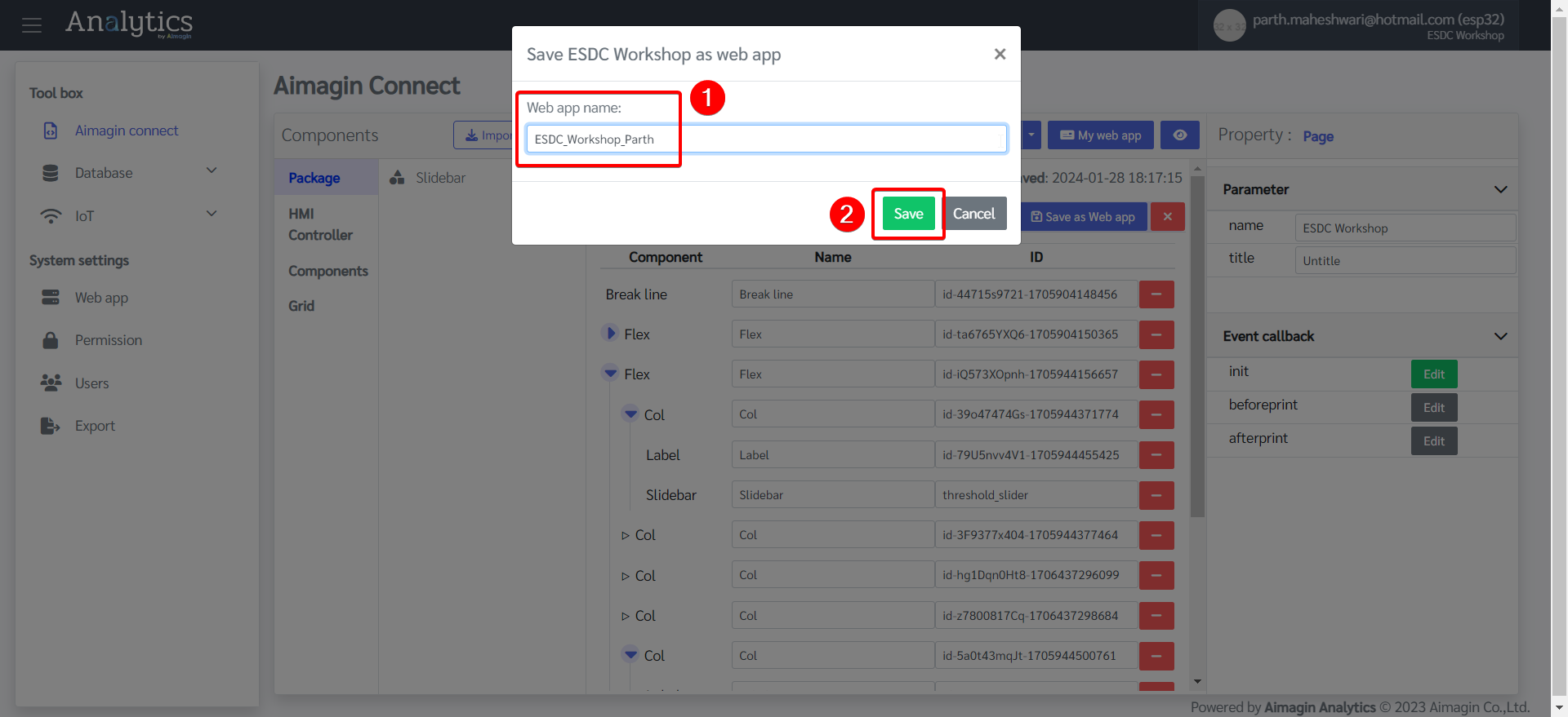
5.Click on "Save as Web app" and give a name.
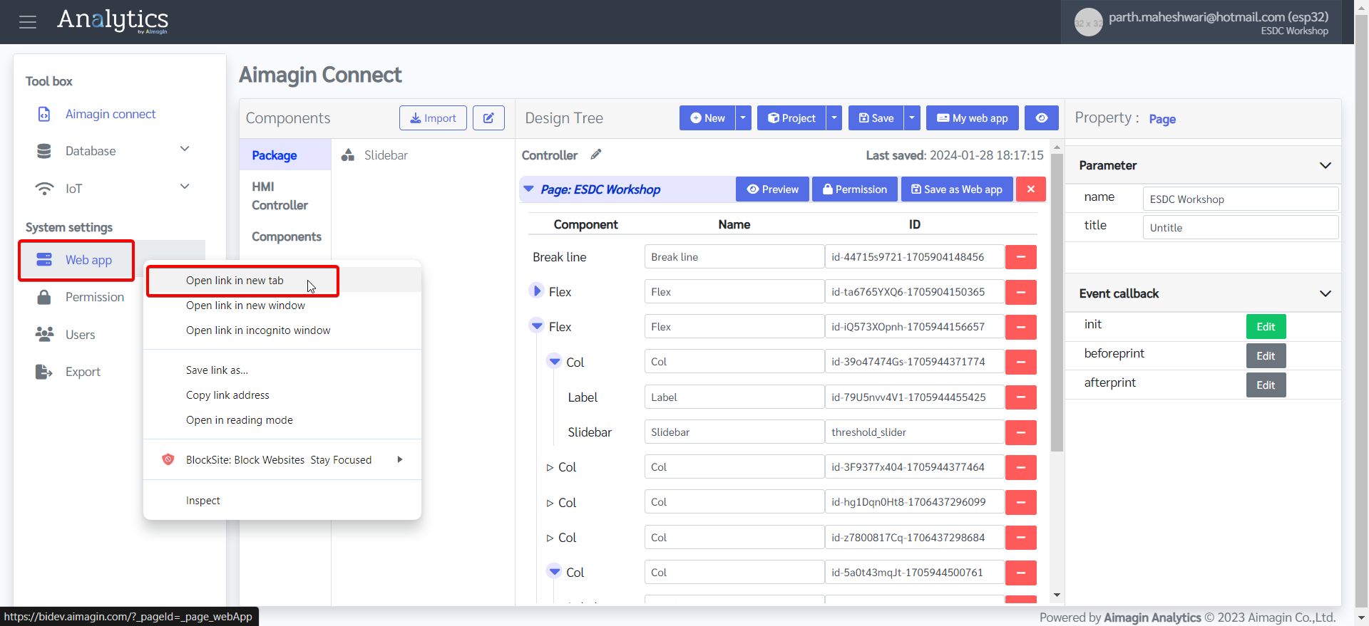
6.System settings tab (in the left menu) > Right click on Web app > Open in new window
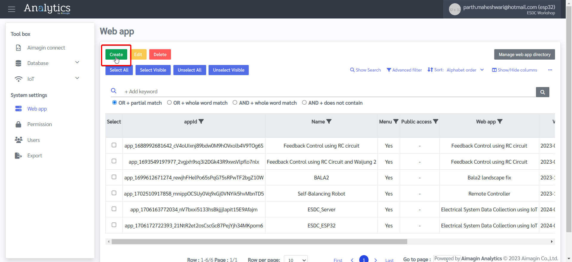
7.Create a web app to publish.
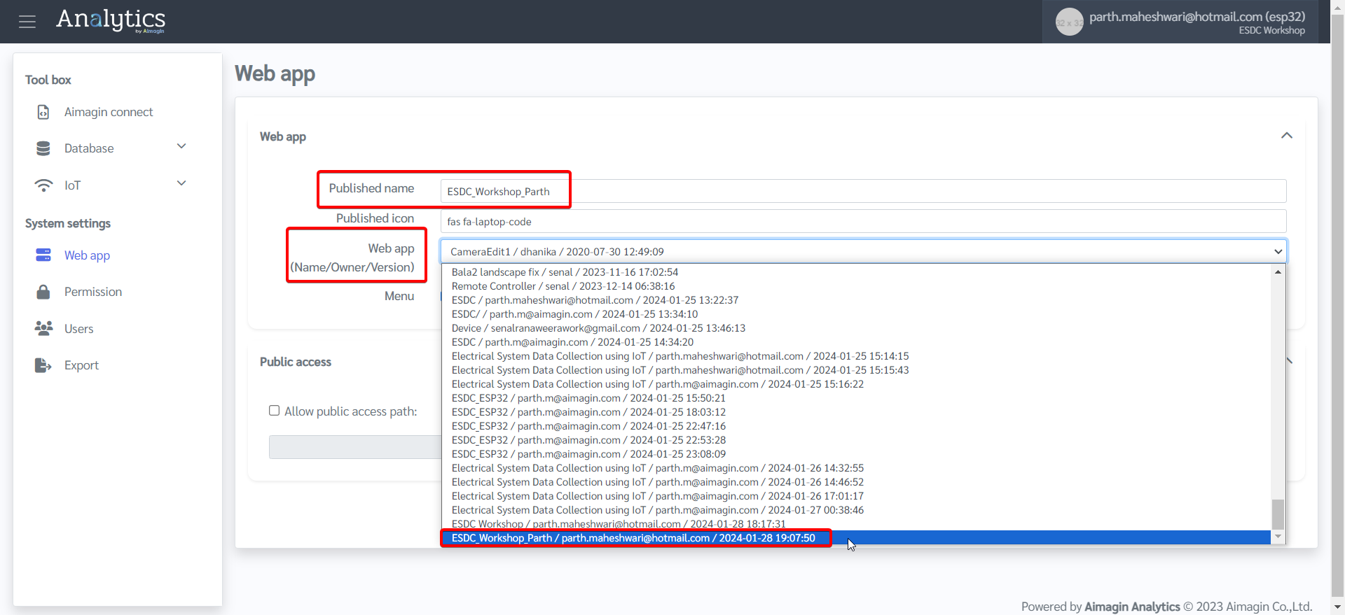
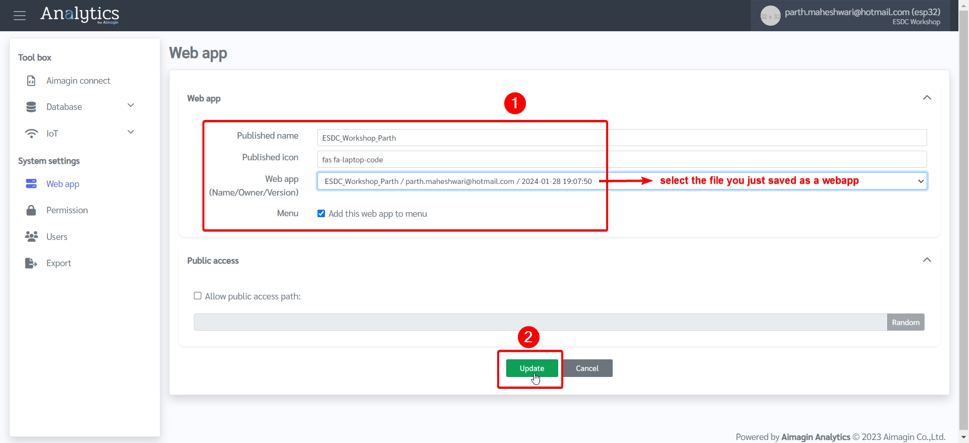
8.Give a name, select the file you just saved as a web app in Step 5, and click on Update.
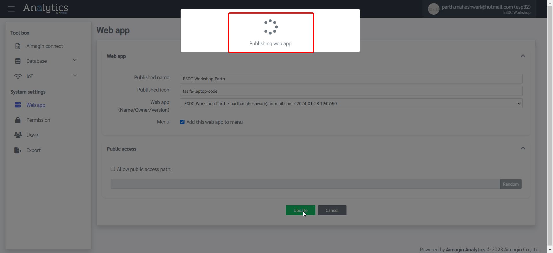
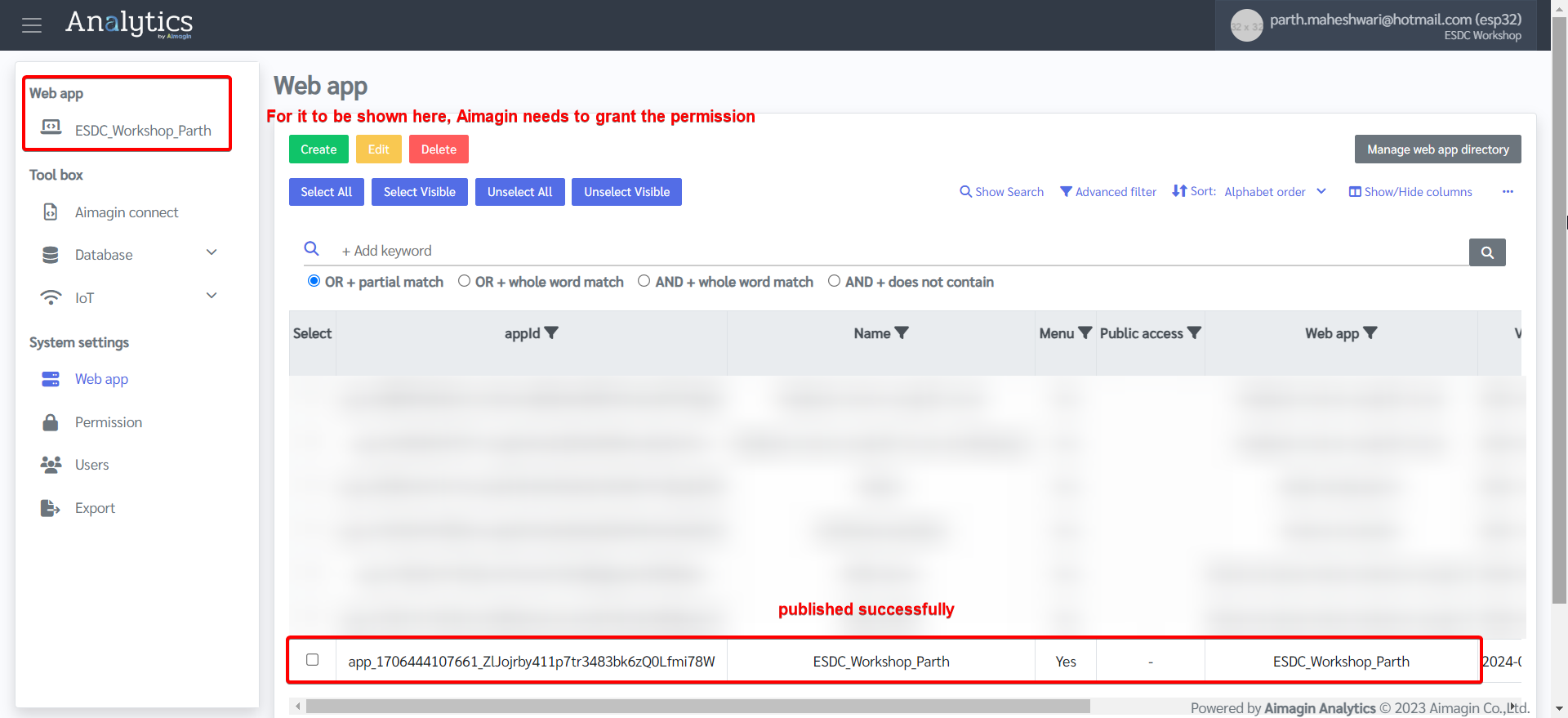
9.Web app will now be published. Even though it will show as published in the table, it will be shown in the menu bar on the left only if Aimagin has granted the permission to do so. If you cannot view it in the left menu, then please contact us before continuing the next steps.
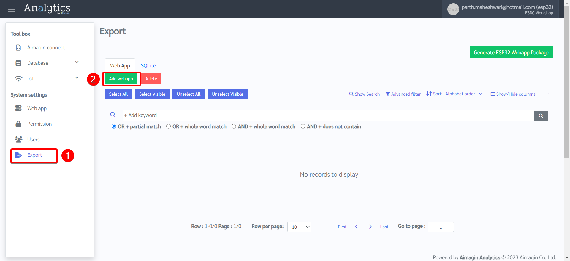
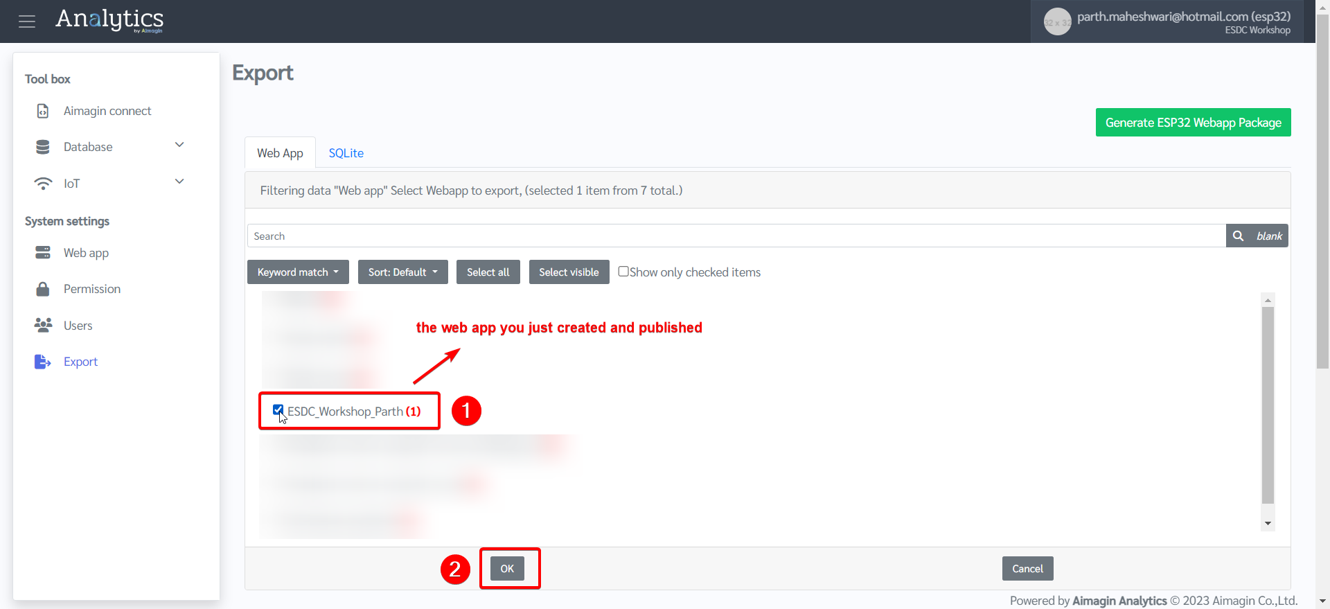
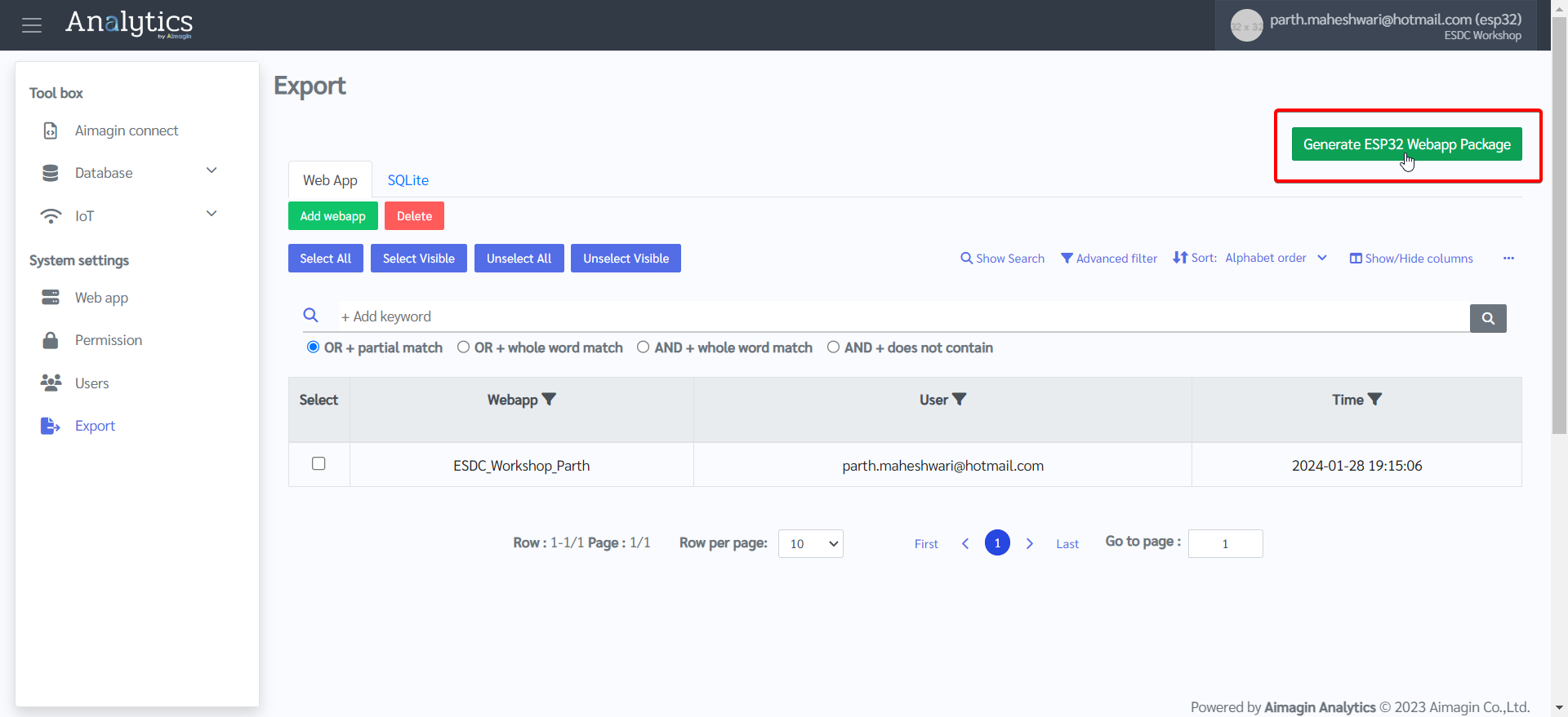
10. System settings tab > Export > Add webapp > Select your web app that you just created and published > Click Ok
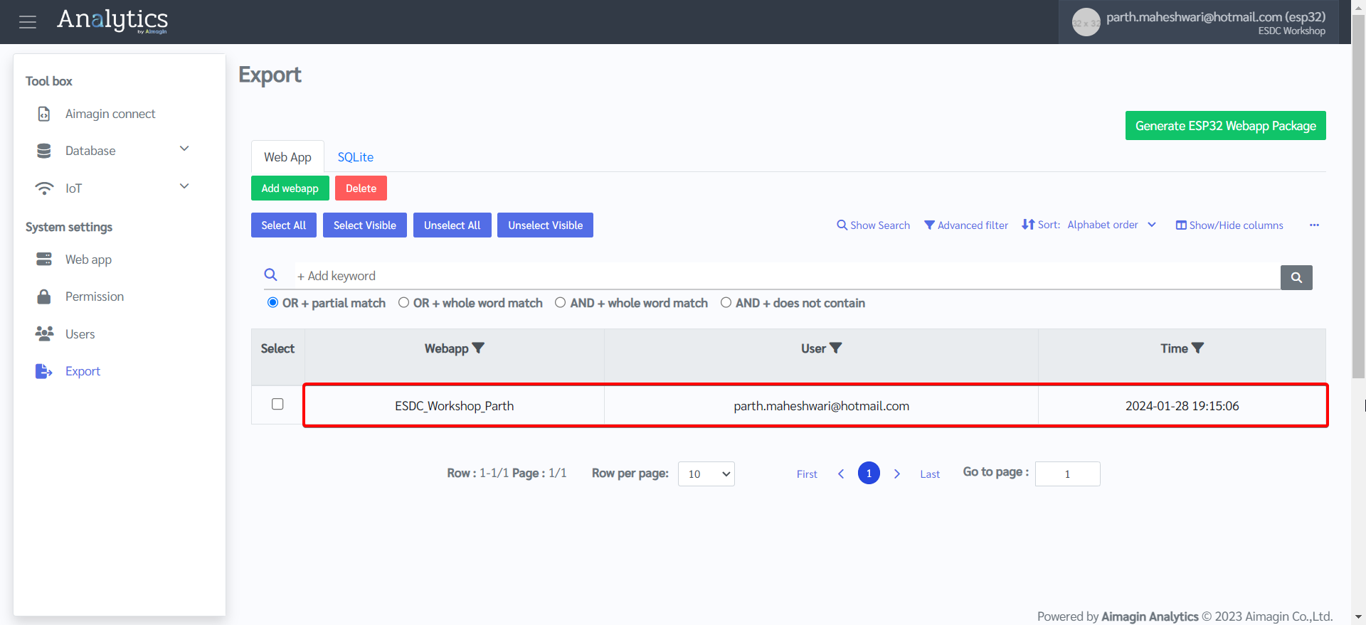
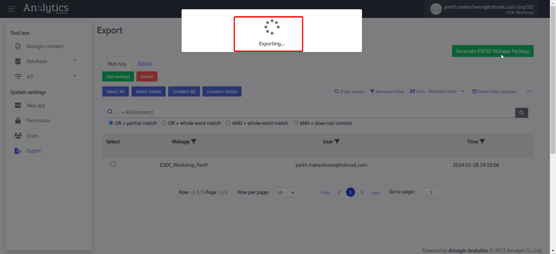
11. Click on Generate ESP32 Webapp Package. This will download the created webapp and related Aimagin Connect files as a .zip file.
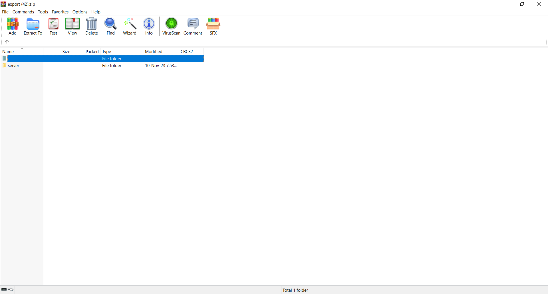
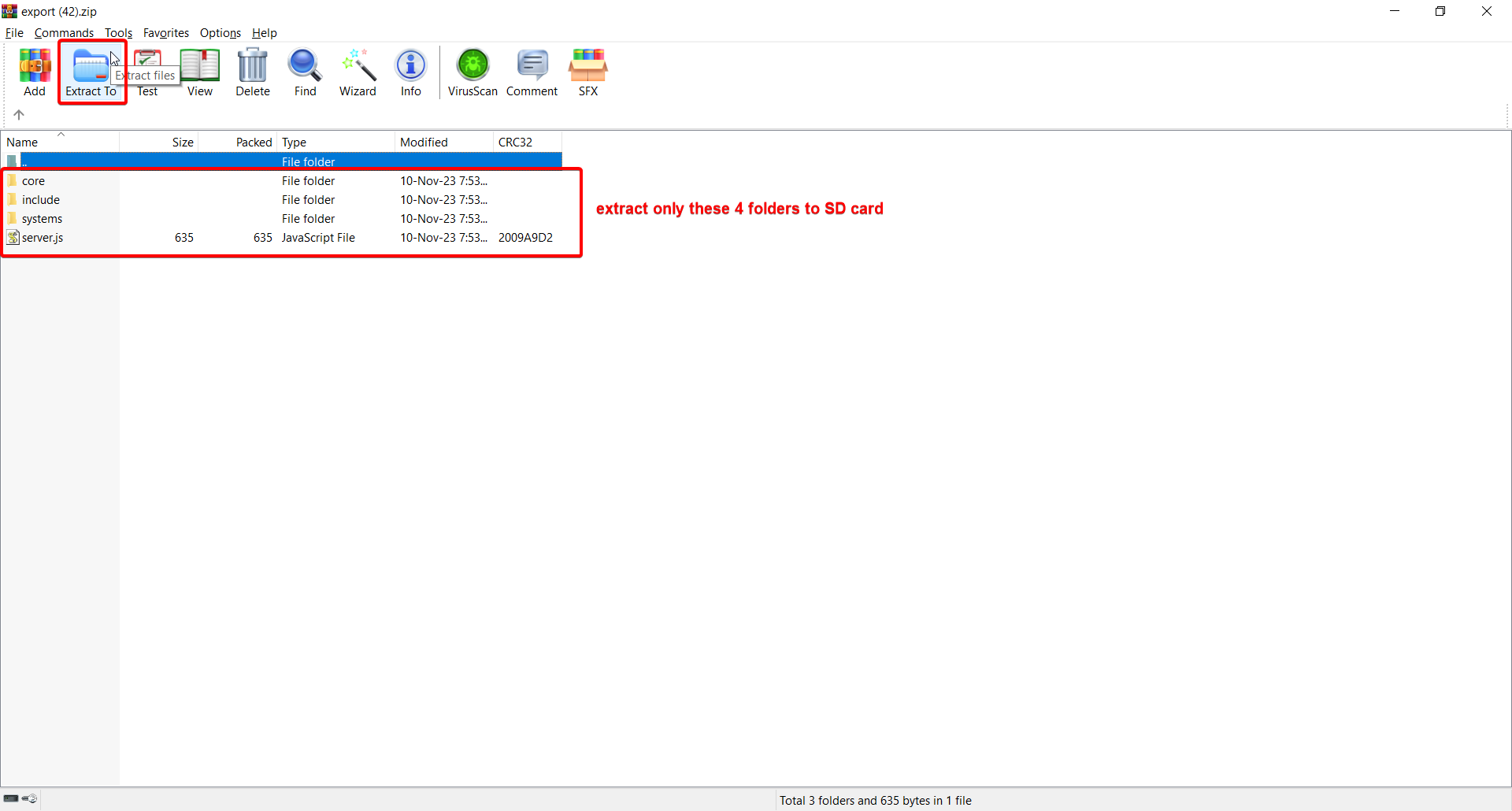
12. Open the .zip file, double click on Server folder, and extract the contents to a SD card.
13. Insert the SD card into ESP32.
The web application side is now complete. We will now move on to Simulink to design the firmware that will allow ESP32 to collect data and publish to the web application, as well as allow the web application to control the ESP32.
PART 3: DESIGN FIRMWARE ON MATLAB/SIMULINK (PART A)
Note: You can download the completed file here, or you can follow the steps and do it yourself as well.
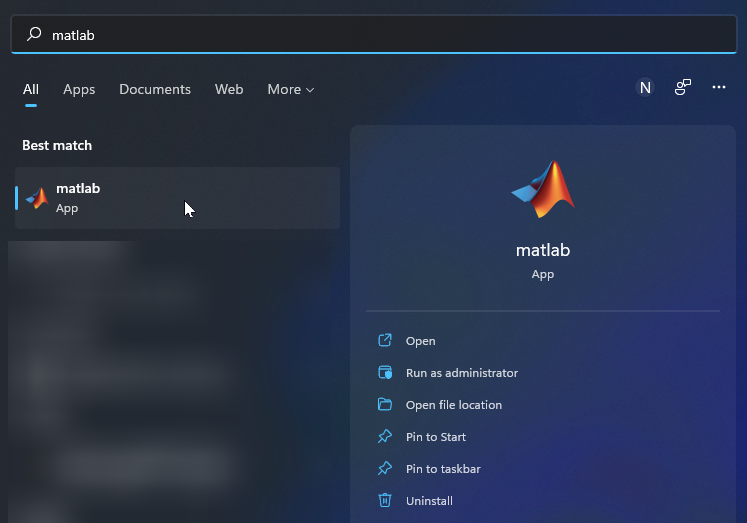
1.Open MATLAB
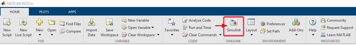
2.Open Simulink
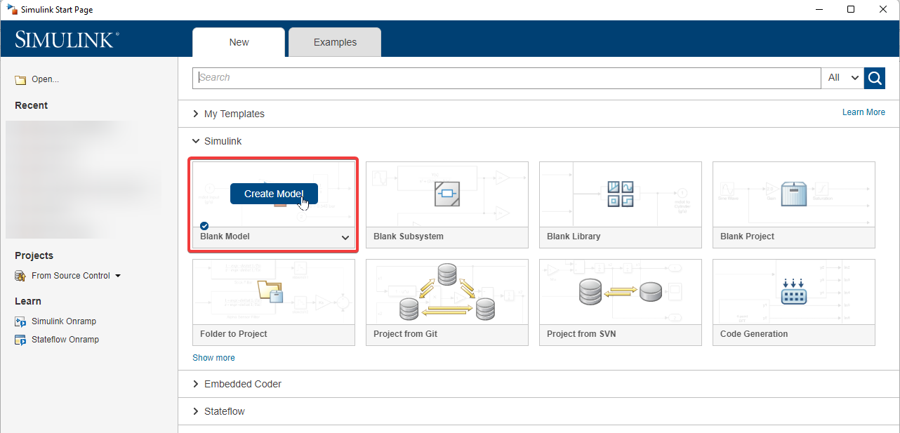
3.Create a blank model
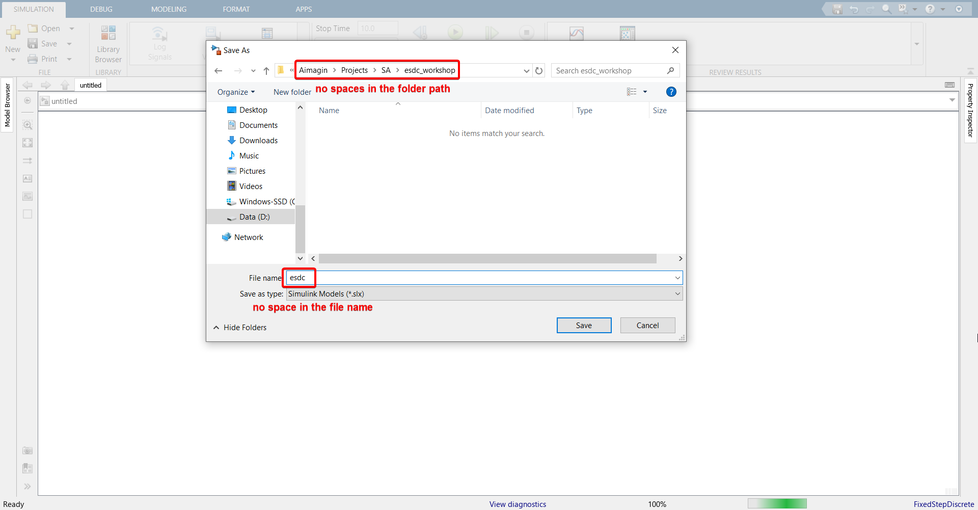
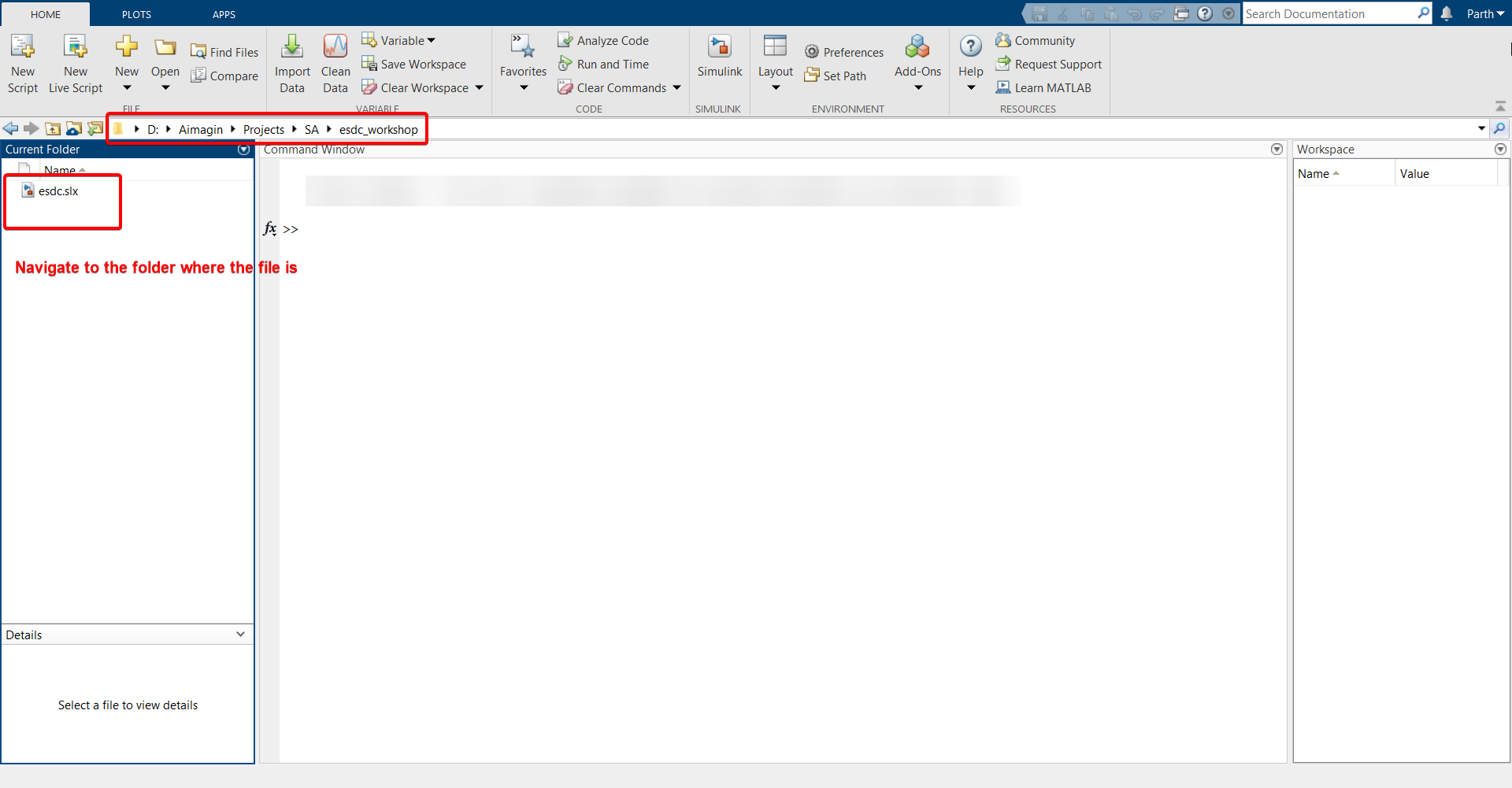
4.Save the file in a folder and give both the folder and the file a name without any spaces. Make sure the file path does not have any spaces either.
5.In MATLAB homepage, navigate to the folder where the file is stored.
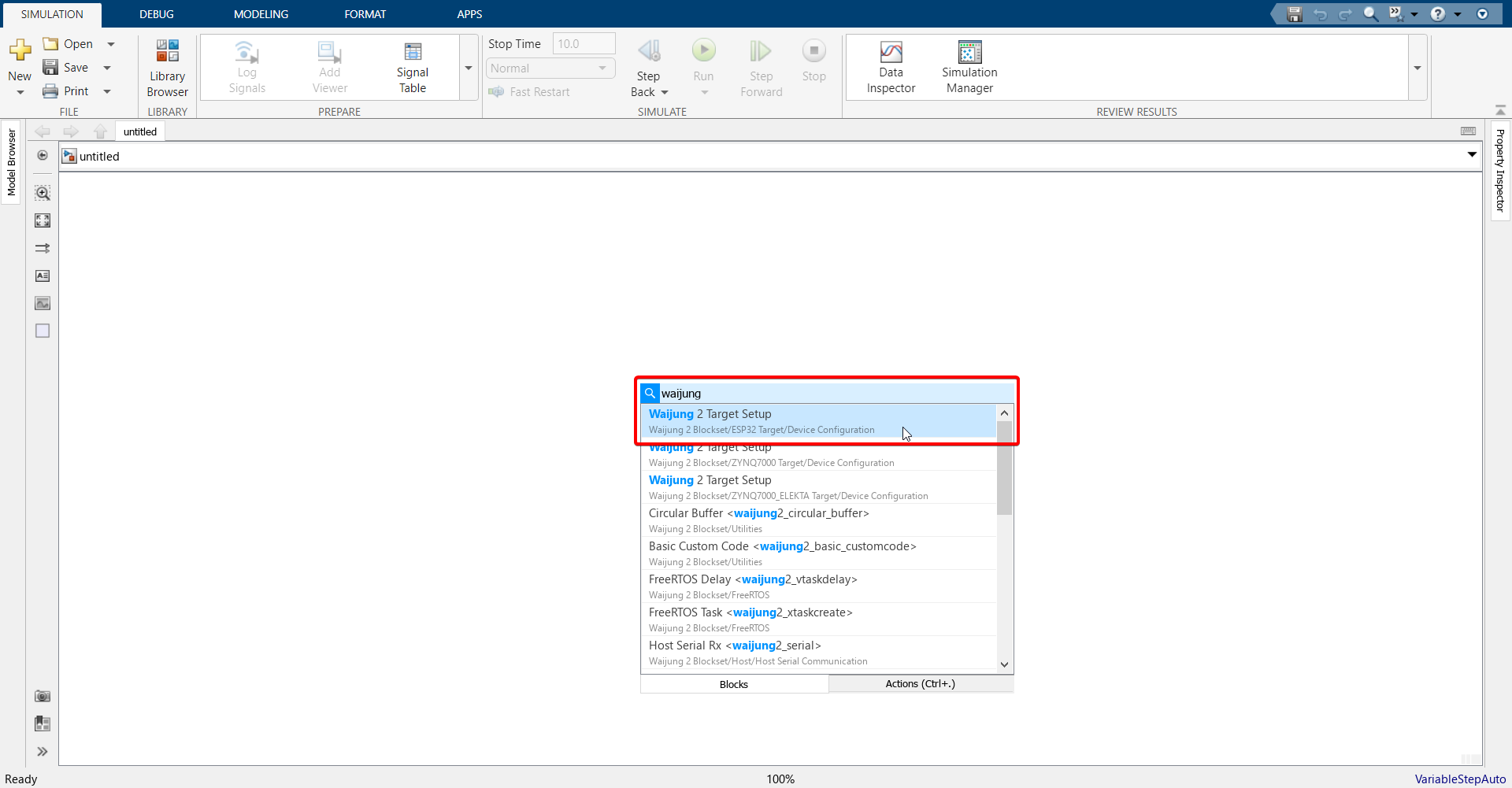
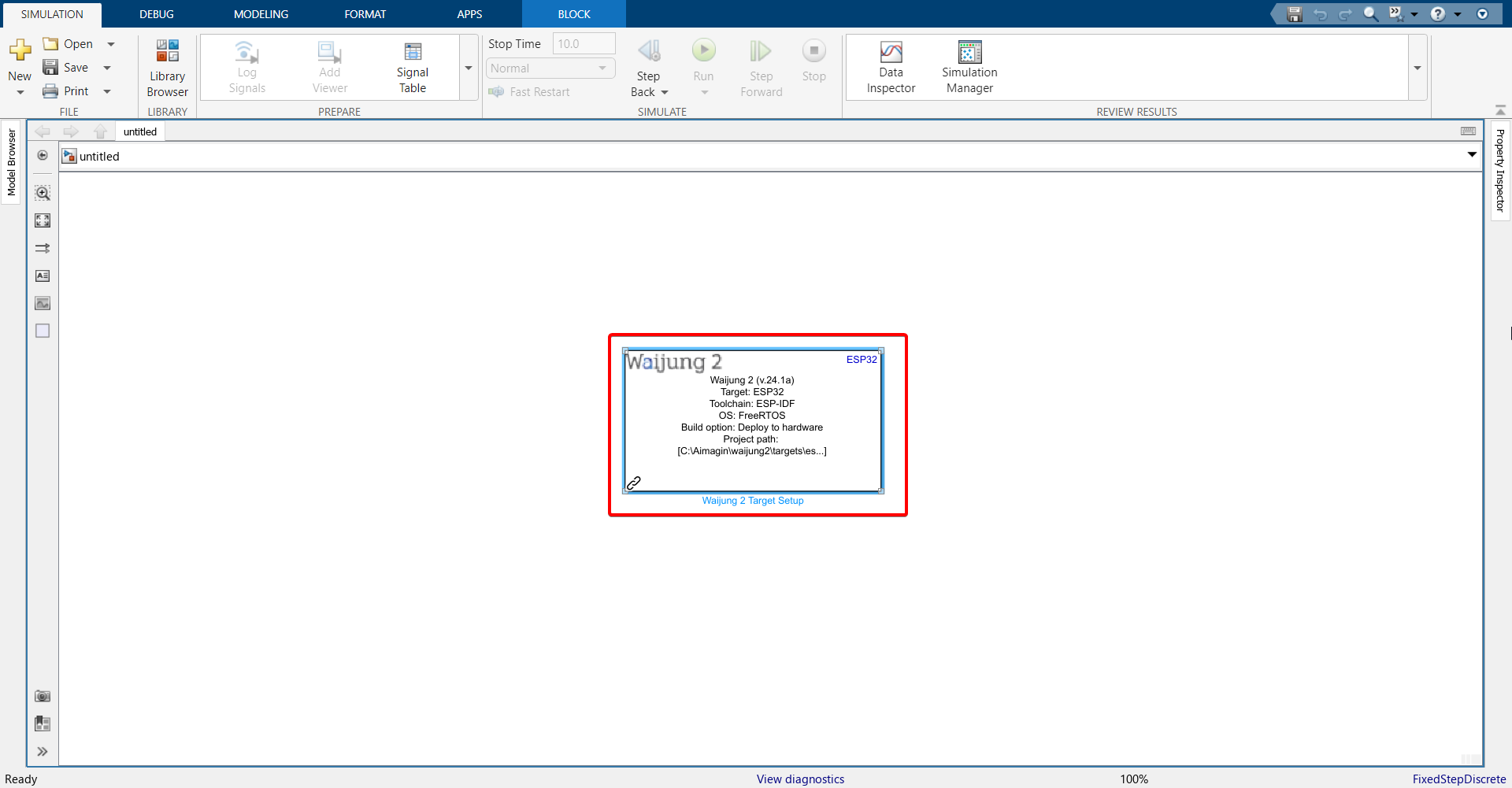
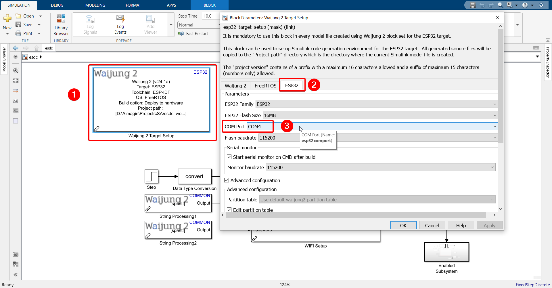
6.Go back to the Simulink model. Double-click in the blank area, search for Waijung 2 Target Setup block and import it.
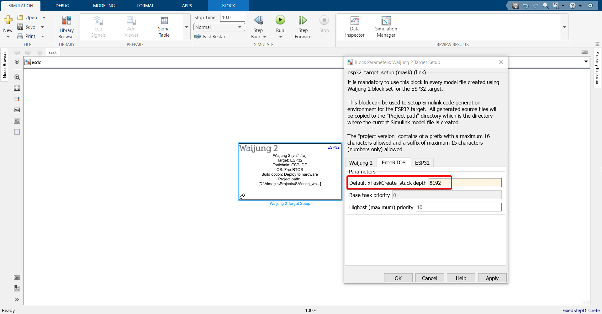
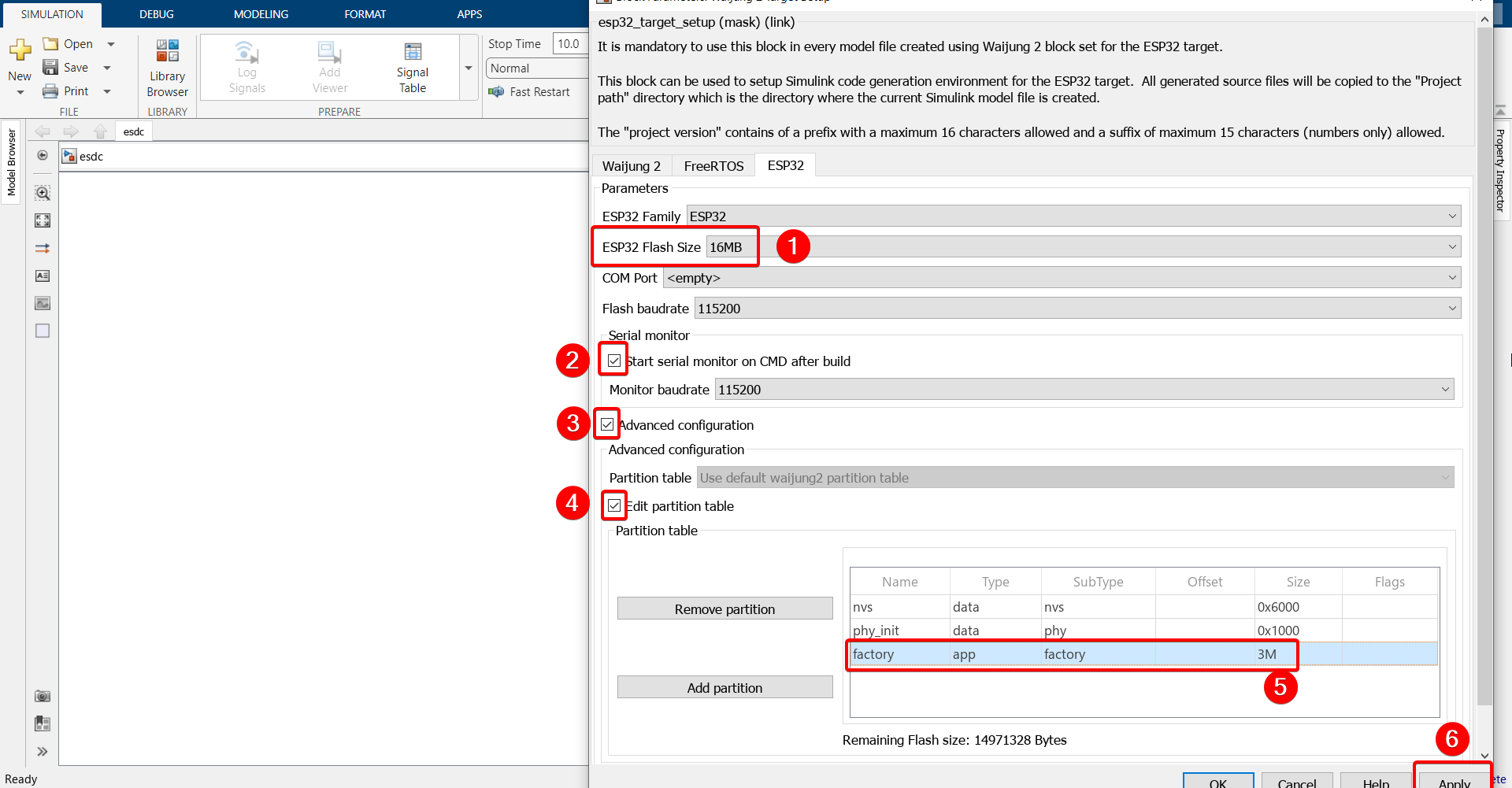
7.Double click on the block and configure as follows.
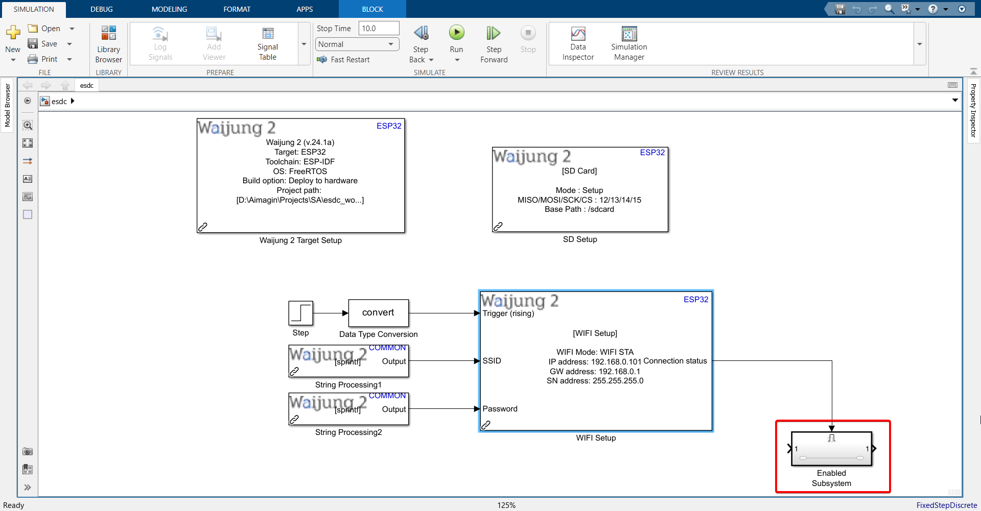
8.Import the following blocks. All block names can be found below the block.
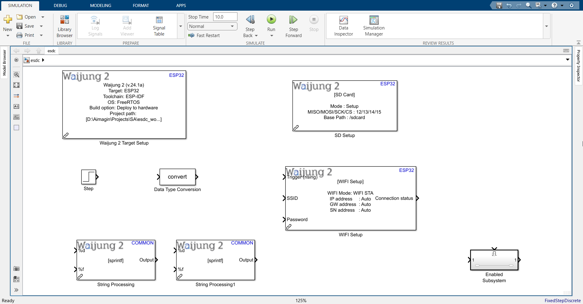
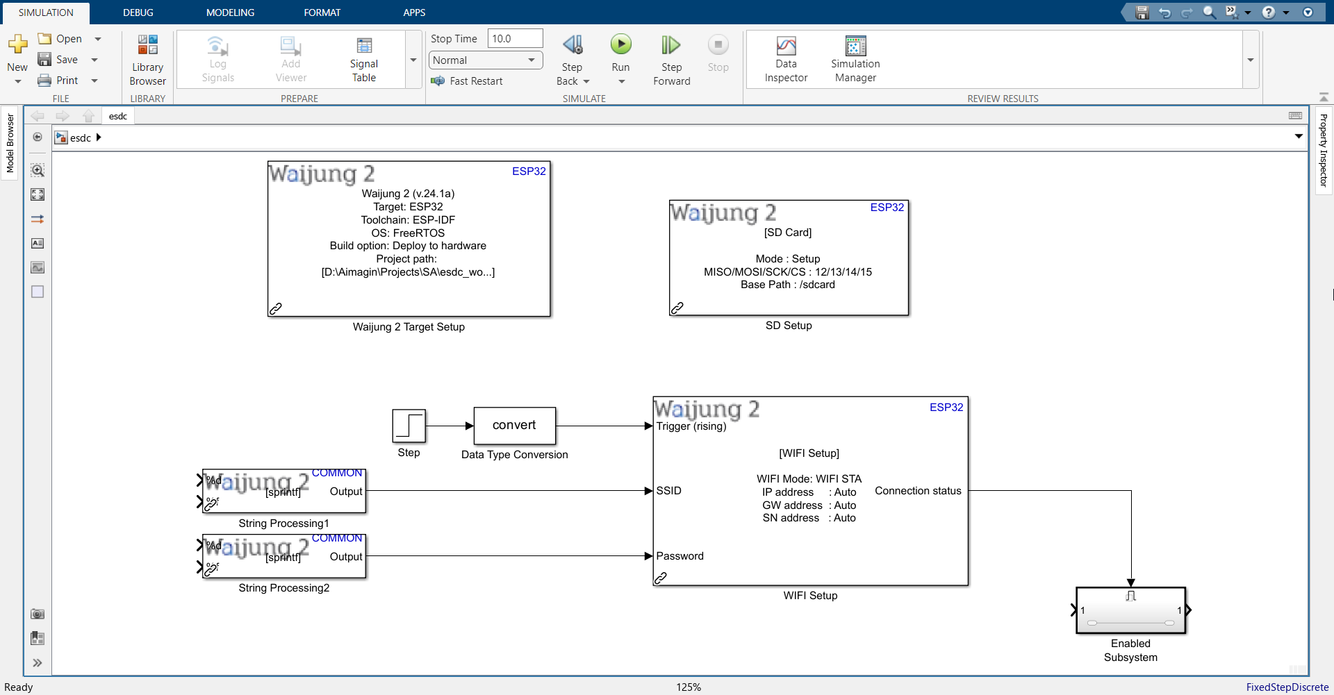
9.Connect them as shown.
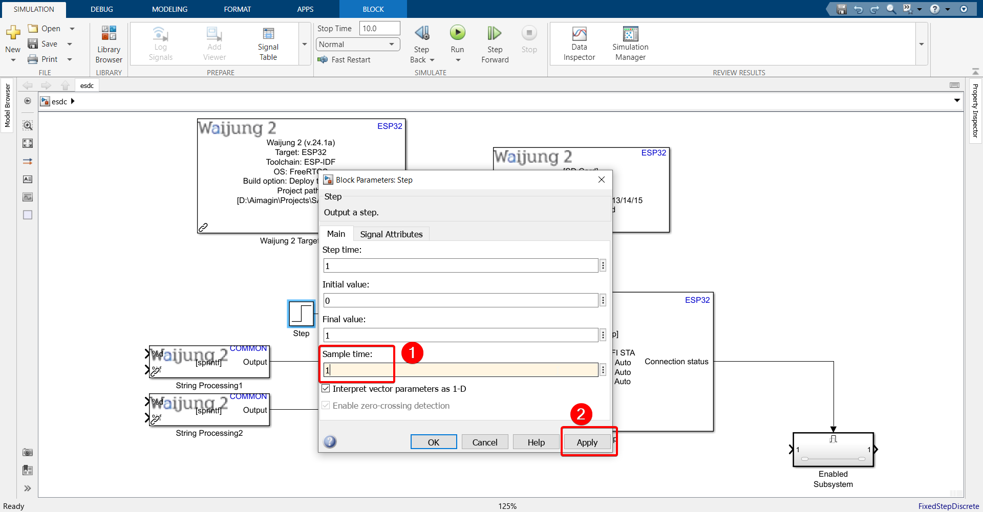
10. Double click the Step block and change sample time to 1.
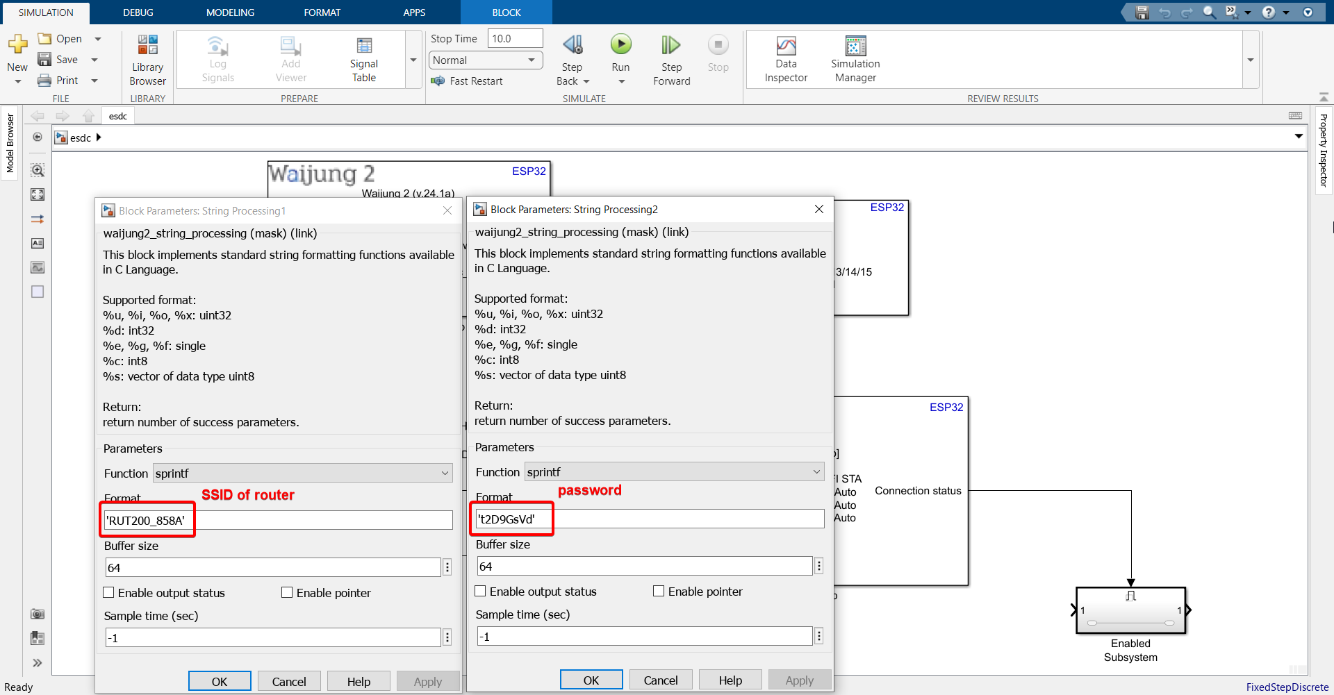
11. In the two String Processing blocks, enter the SSID and Password (in single quotes) of the router you want your ESP32 to connect to. You can use the same router / access point that your computer is using to connect to the internet. We will be using WiFi Station mode, since later on we need to send data acquired by ESP32 to the server via MQTT. That can only be done in WiFi Station mode.
Note: All ESP32 boards only support 2.4GHz bandwidth (except the recently released ESP32-C5 which also supports 5GHz), so make sure the Access Point you connect your ESP32 board to in WiFi STA mode lies in the 2.4GHz frequency range.
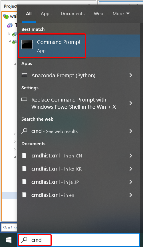
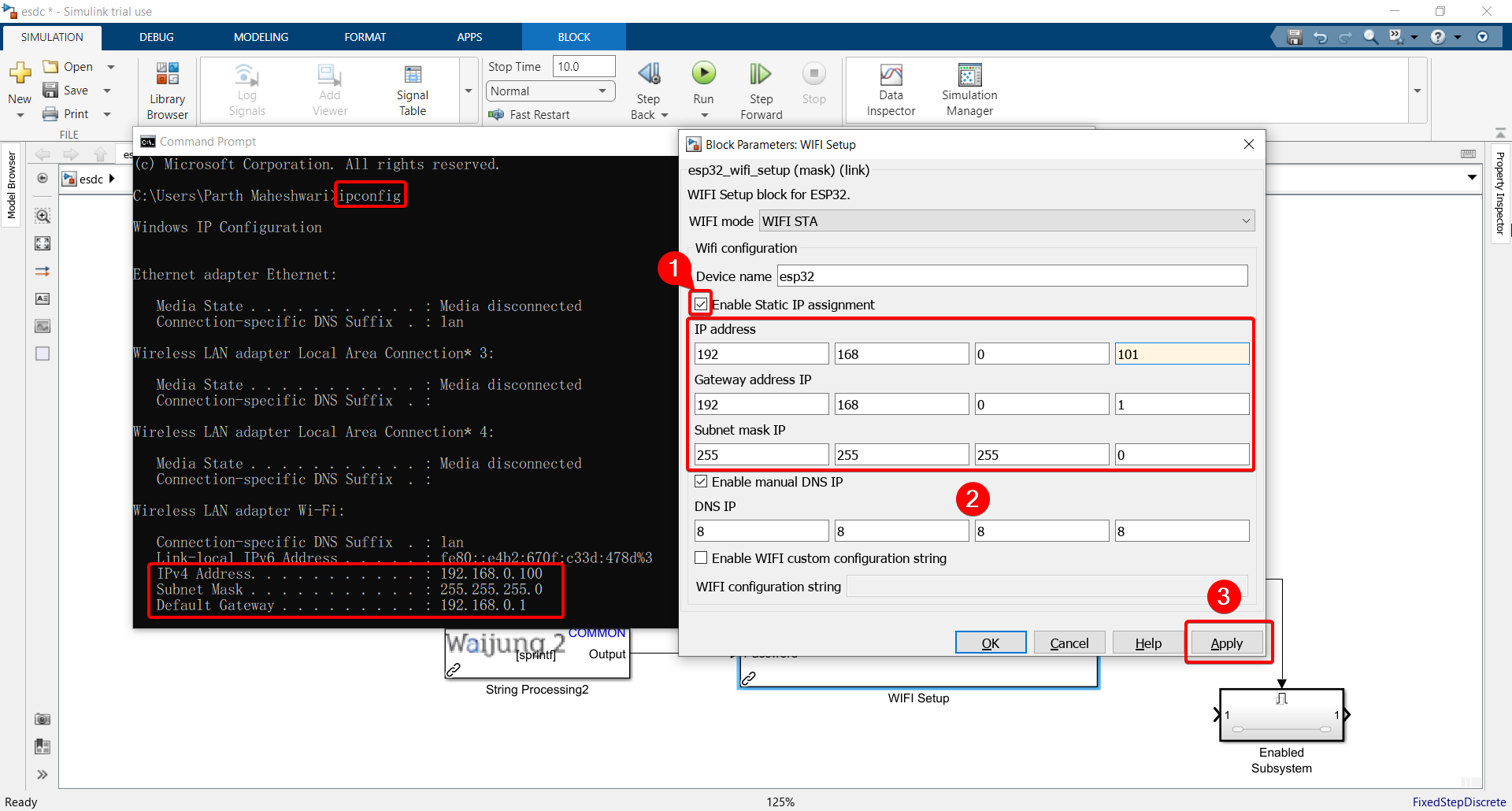
12. For the IP address, Gateway, and Subnet mask, search for "command prompt" or "cmd" and type "ipconfig" to find the configurations and input them into the WiFi Setup block.
Note: For the IP address, choose any number between 0 to 255 for the last 3 digits, except the IPv4 address listed in command prompt (since that is the IP address assigned to your computer). That will then be the IP address assigned to your ESP32 from the router you are connecting to.
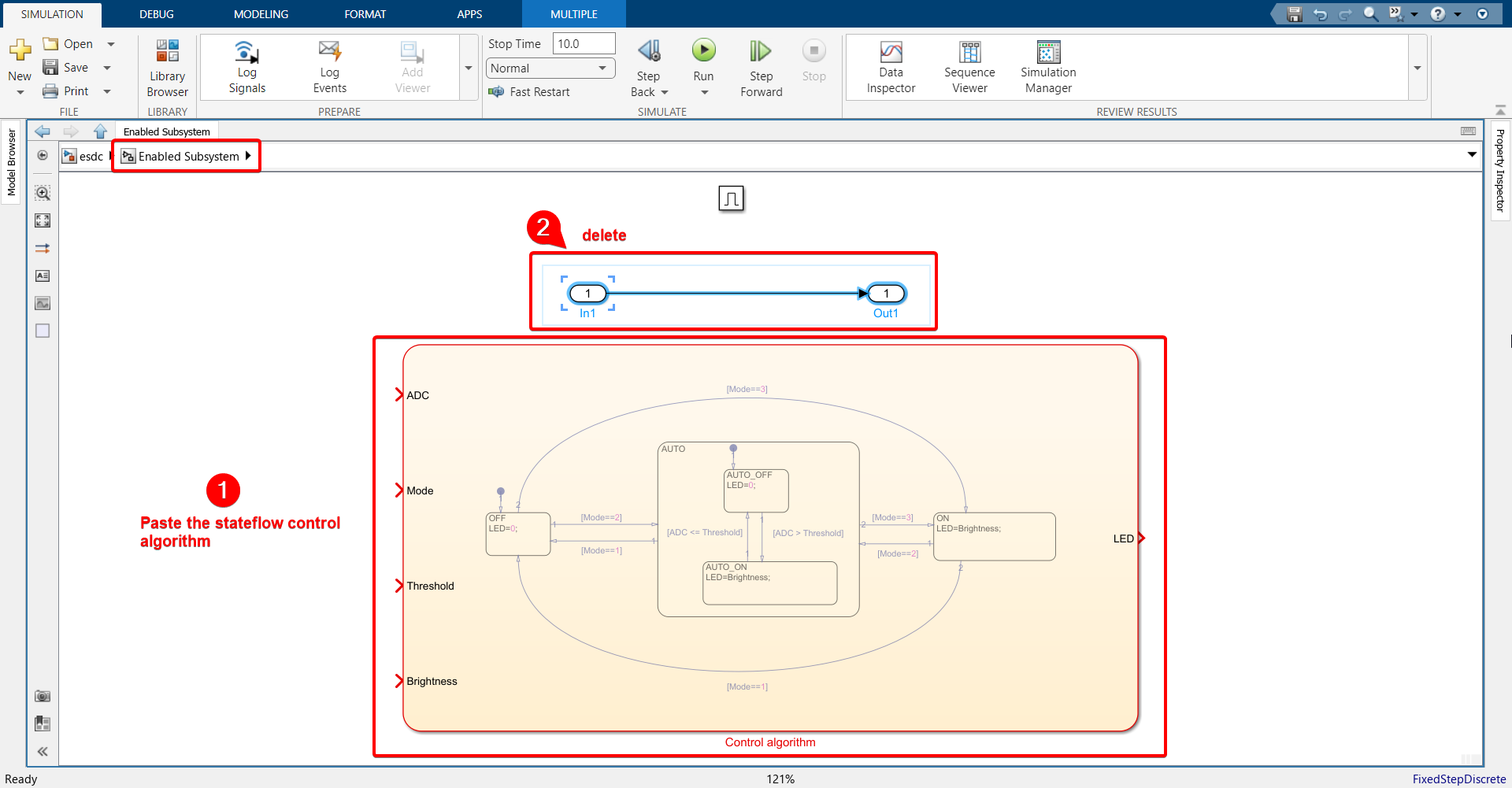
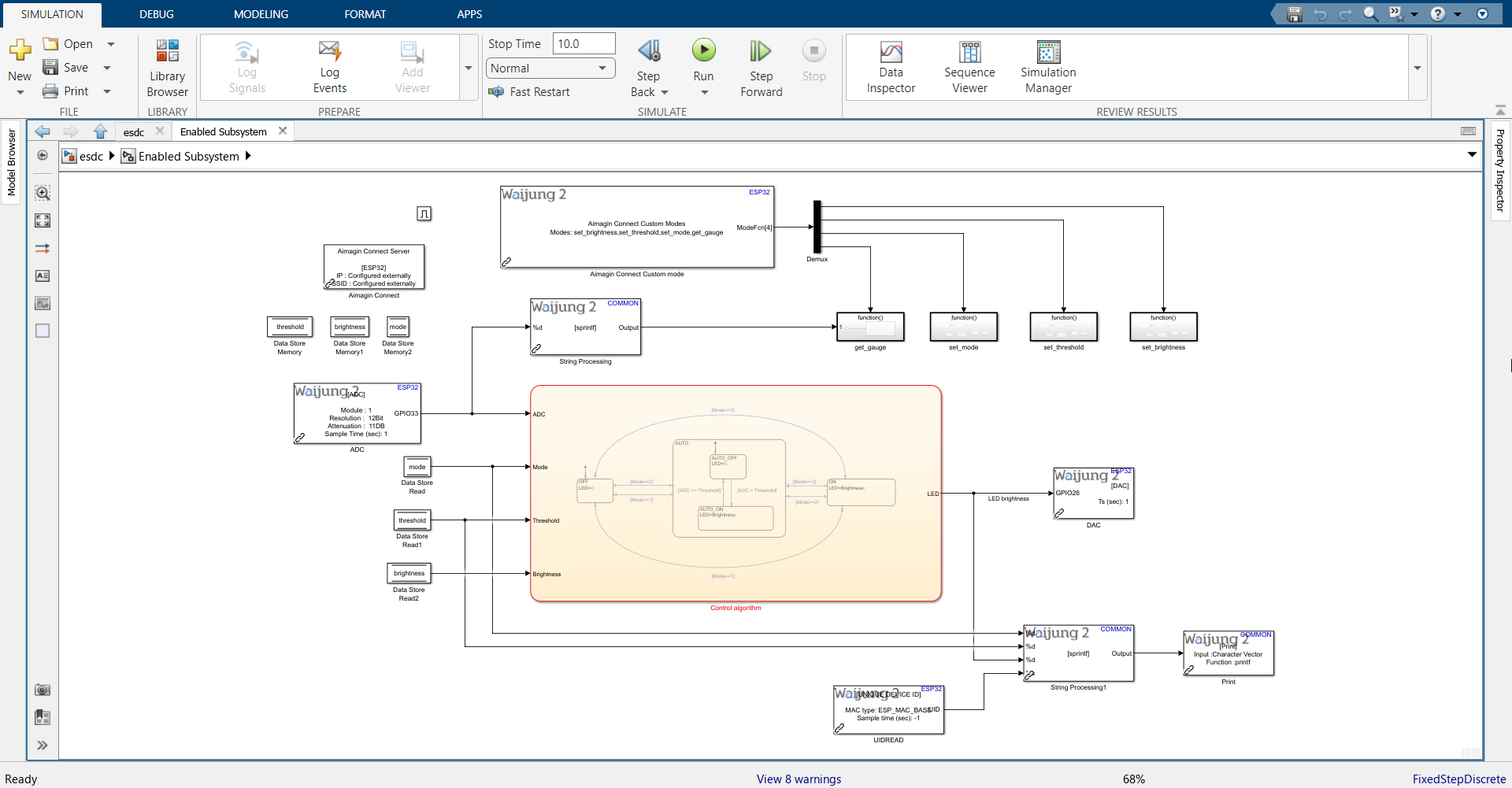
13. Open the Enabled Subsystem, which will only be triggered when WiFi connection status is successful. Copy the Stateflow control algorithm from Exercise 6 and paste it in the Enabled Subsystem.
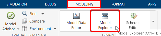
14. Go to MODELING tab > Model Explorer and change data type of LED to uint32.
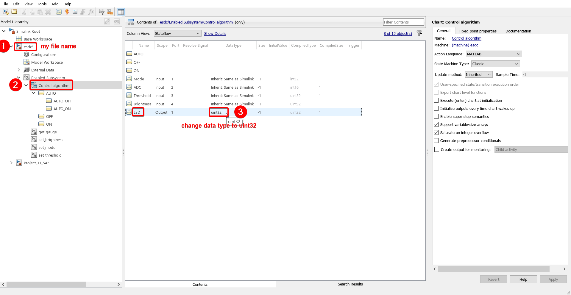
15. Close the Model Explorer and save the file. That is the only way to apply the changes made in the Model Explorer.
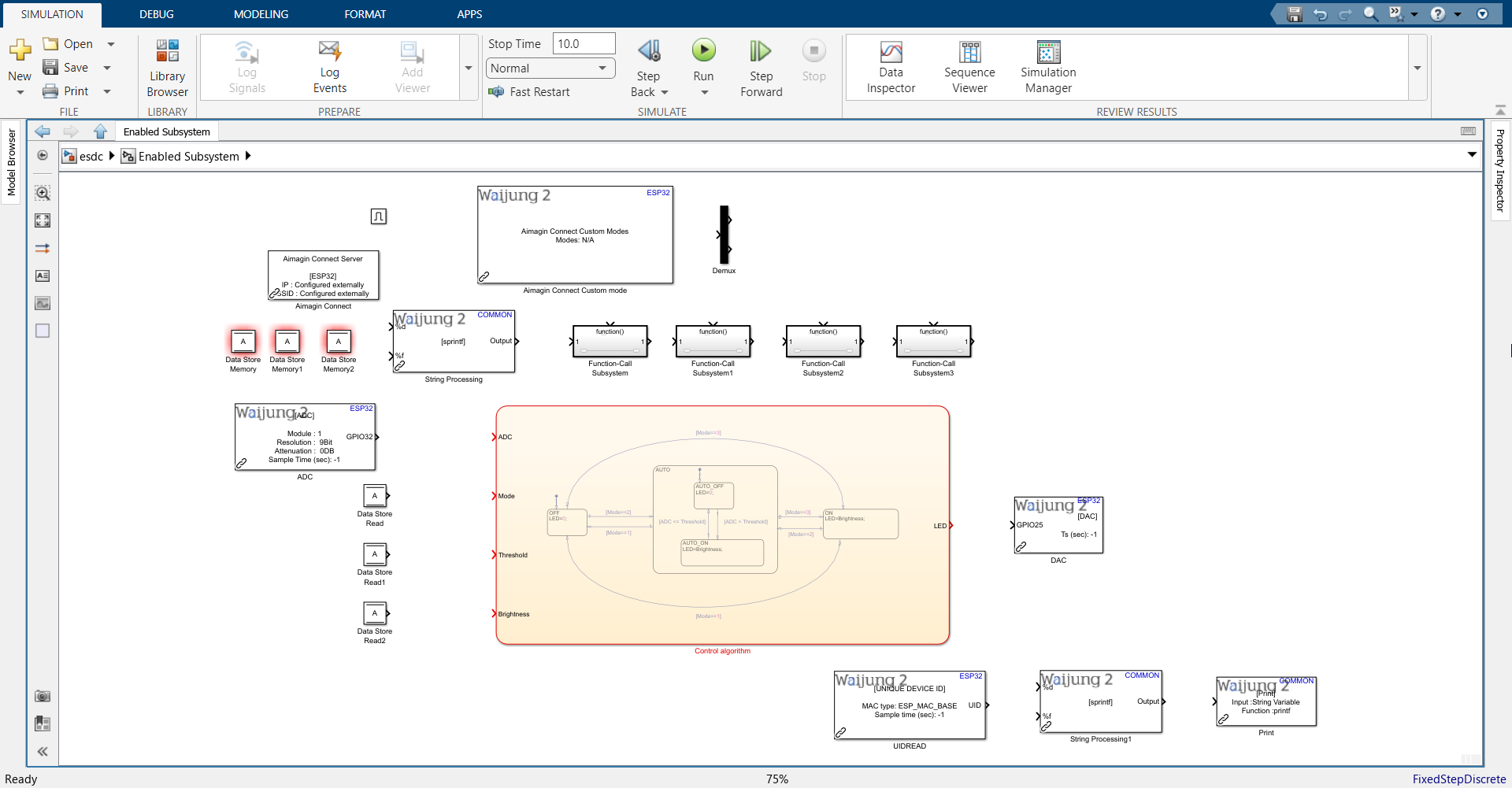
16.Import the following blocks. Block names are below each block.
Note: Please import the UIDREAD block only if you have a Waijung 2 Professional or Commercial License.
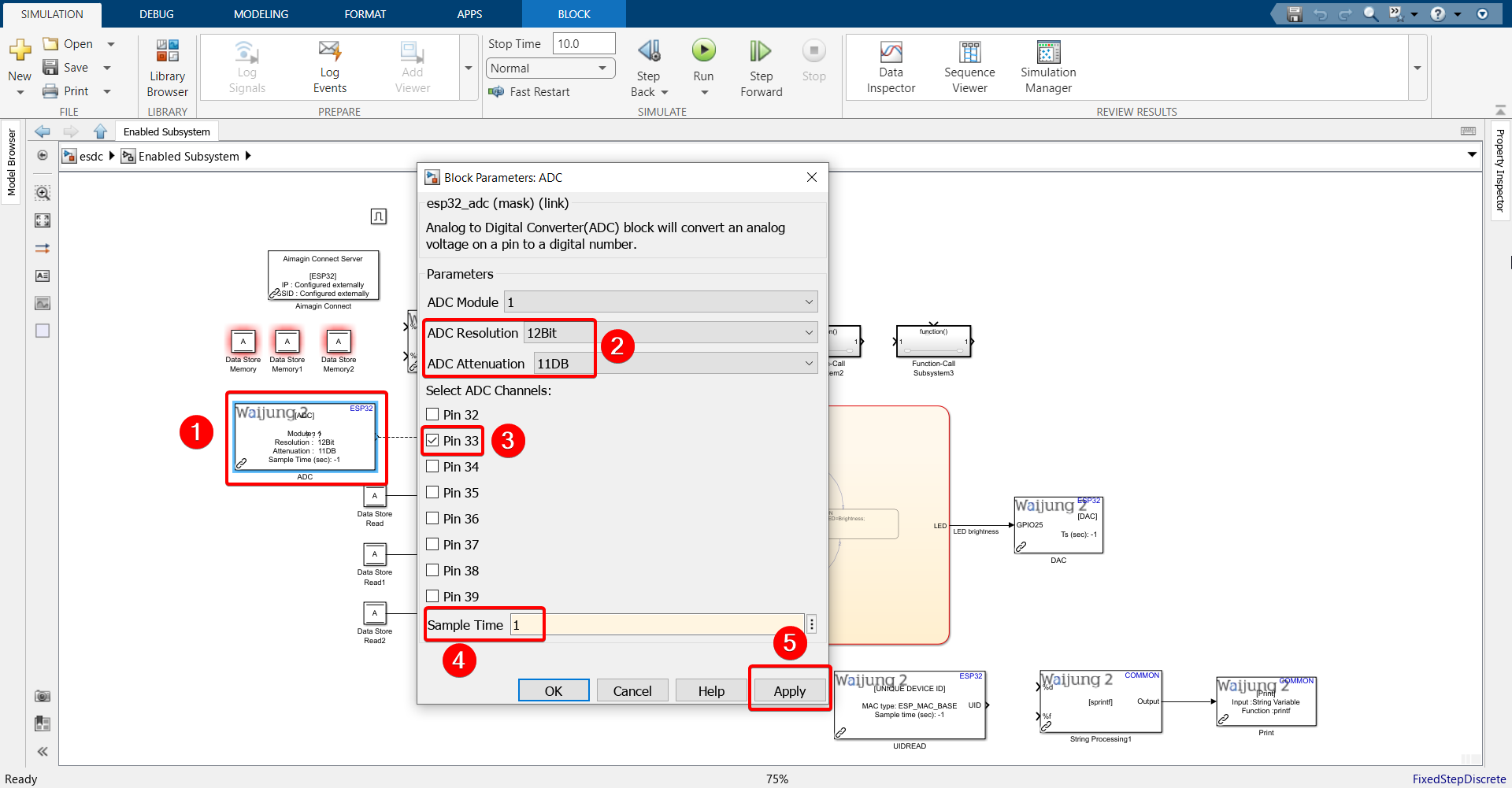
17. Configure ADC block as shown.
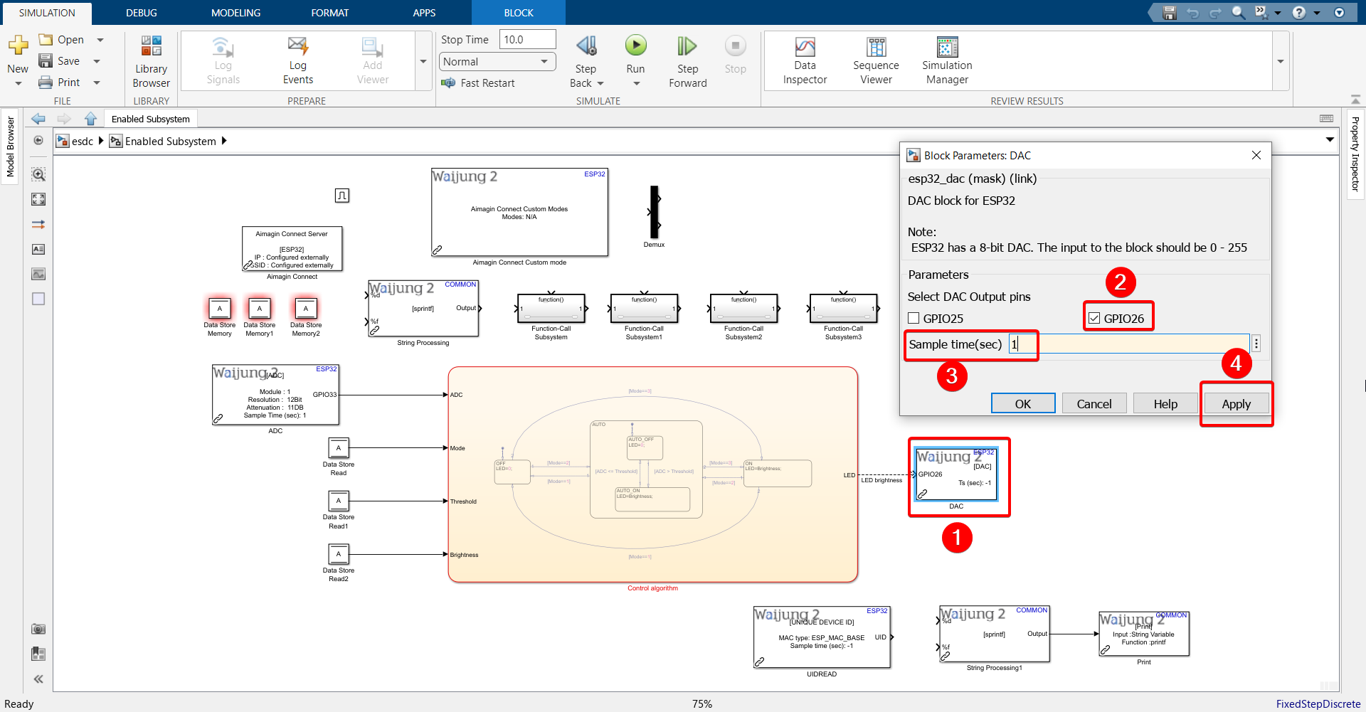
18. Configure DAC block as shown.
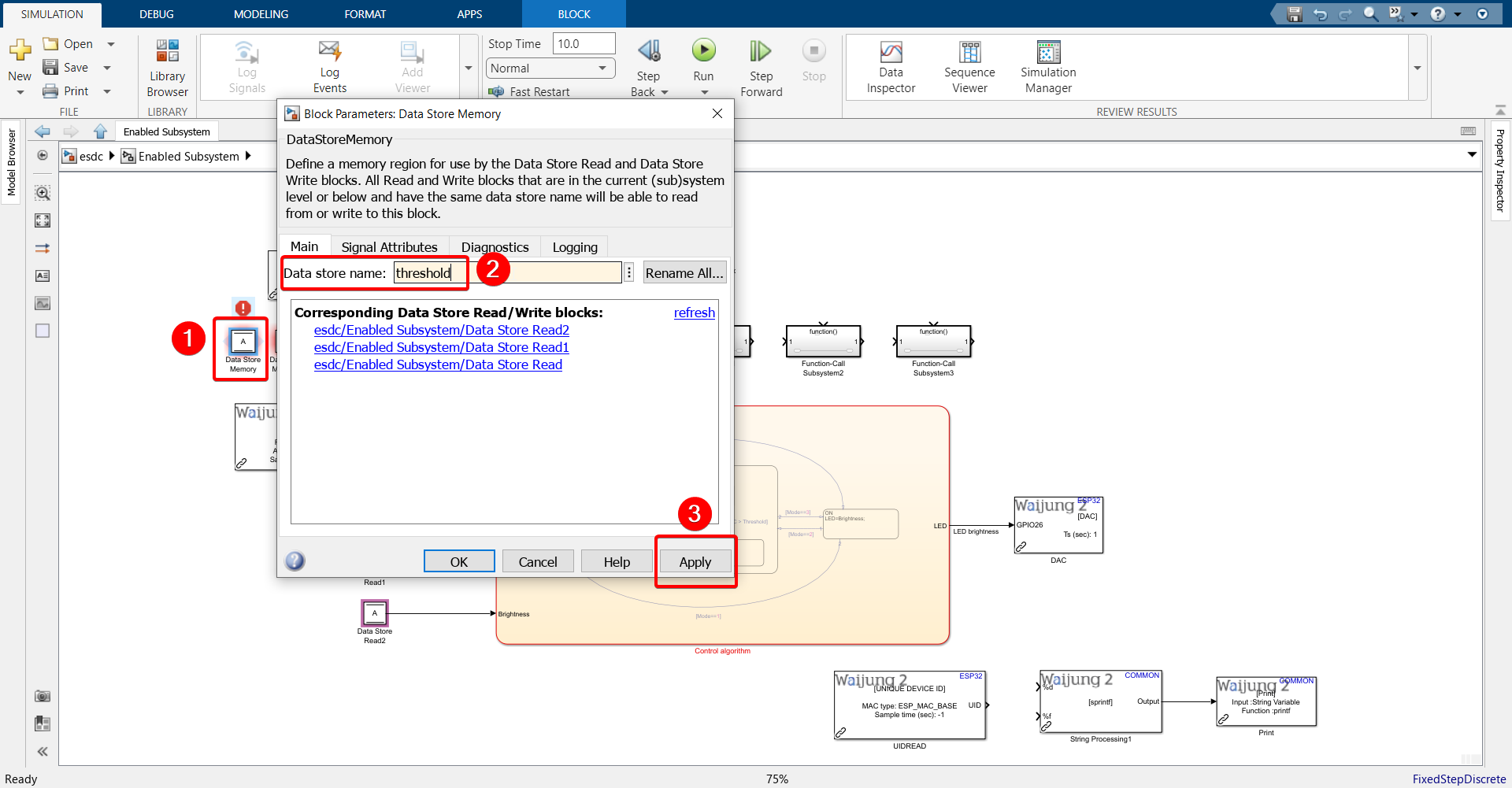
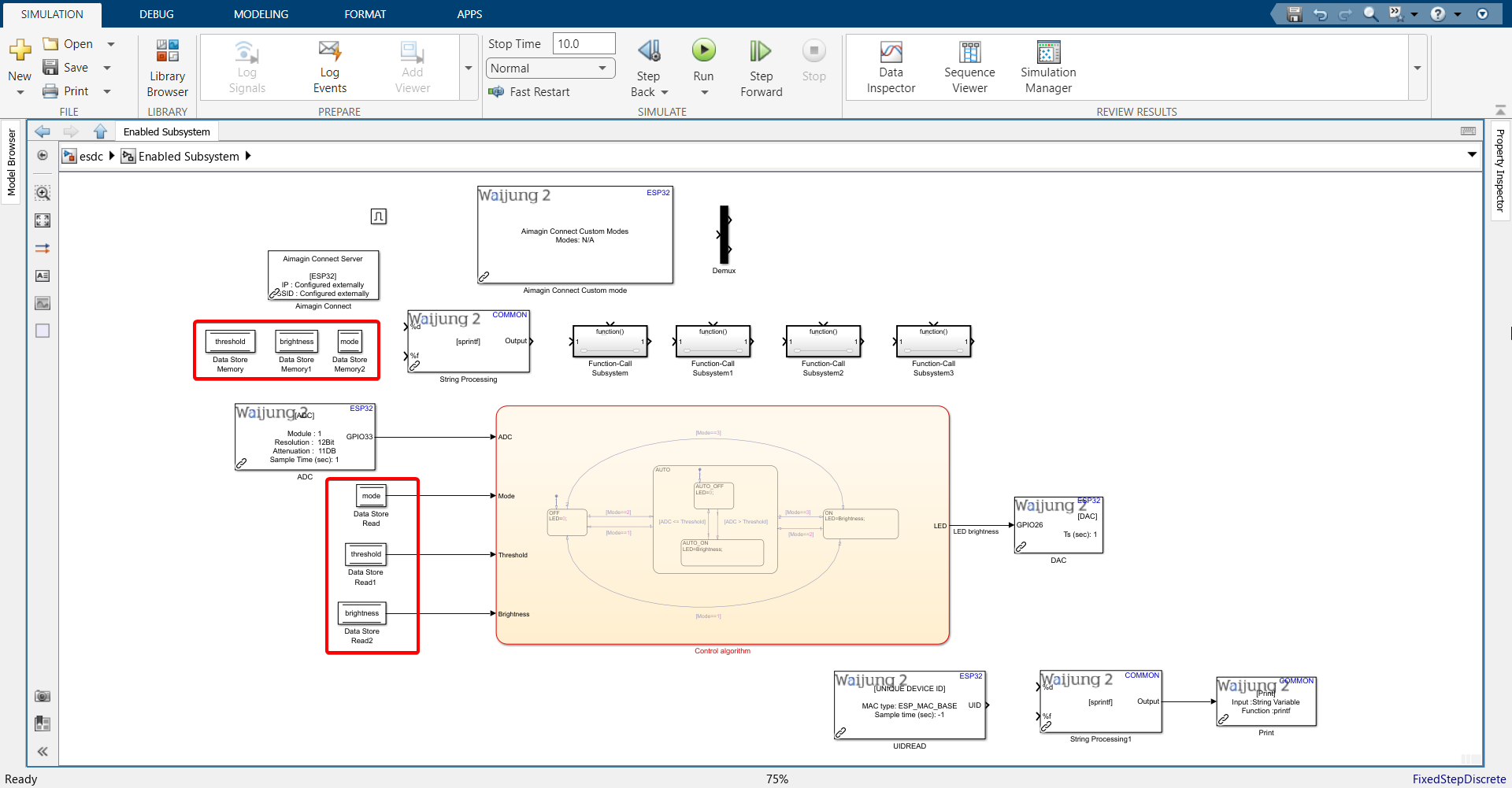
19. Configure Data Store Memory and Data Store Read blocks.
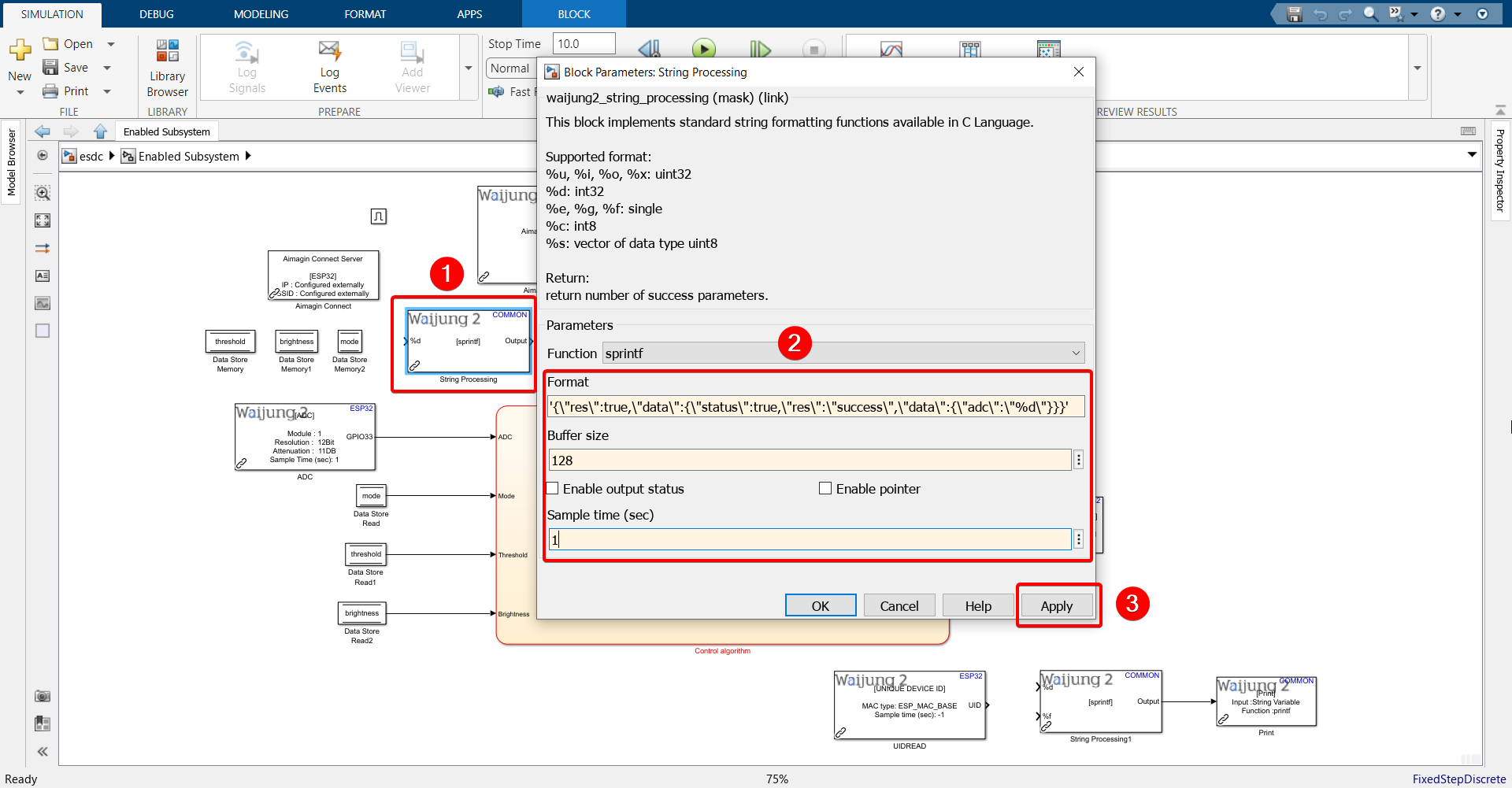
20. Configure String Processing block.
Paste the following into the Format text field: '{\"res\":true,\"data\":{\"status\":true,\"res\":\"success\",\"data\":{\"adc\":\"%d\"}}}'
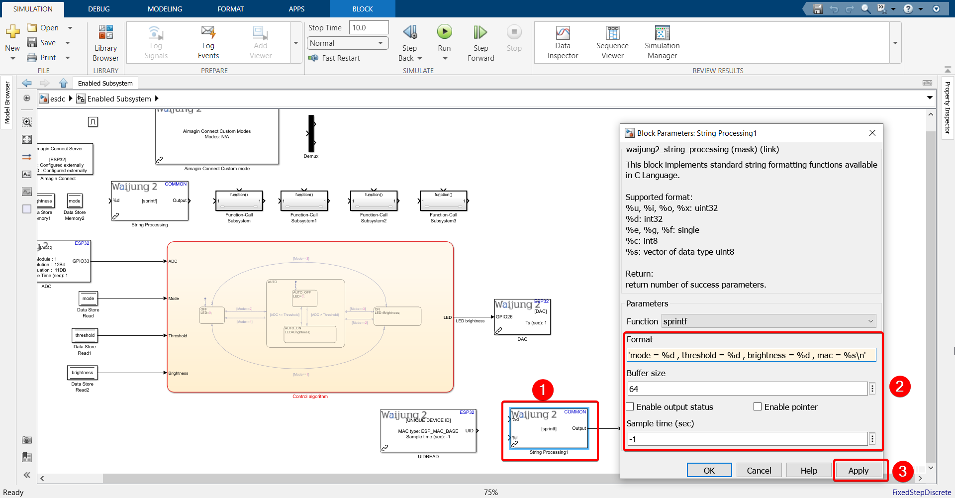
21. Configure String Processing block.
Note:
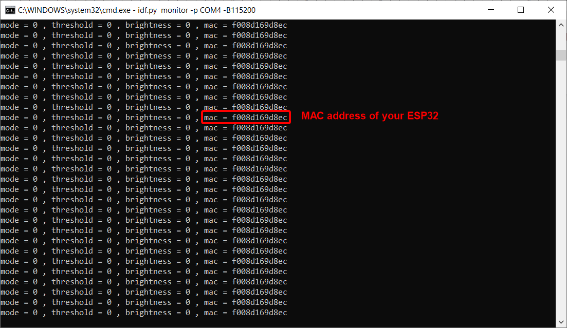
Paste the following into the Format text field: 'mode = %d , threshold = %d , brightness = %d , mac = %s\n' if you have the UIDREAD block imported.
Paste the following into the Format text field: 'mode = %d , threshold = %d , brightness = %d\n' if you do not have the UIDREAD block imported.
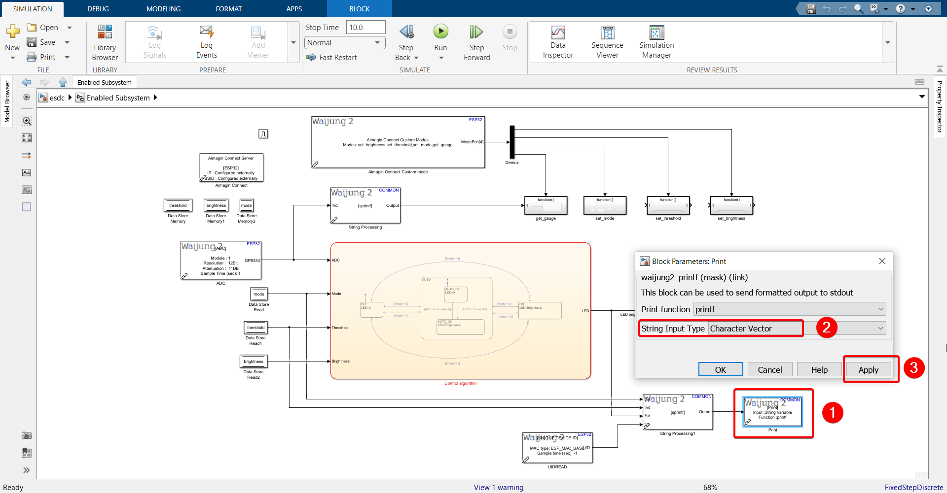
22. Configure Print block.
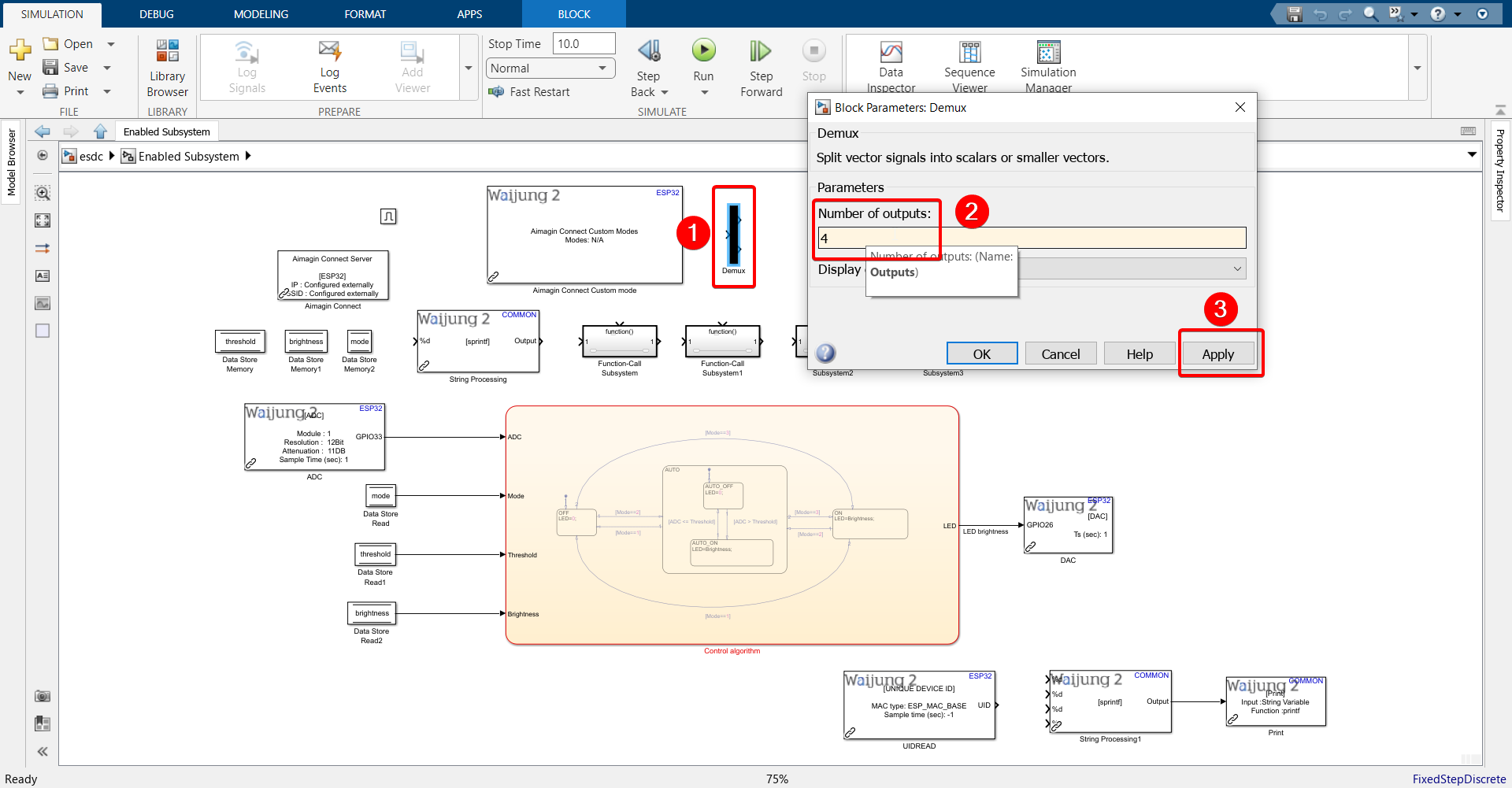
23.Configure Demux block.
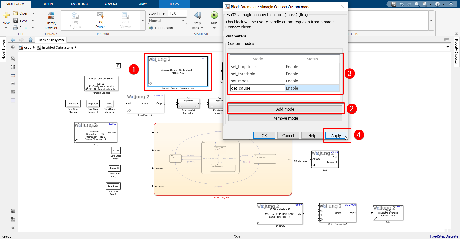
24. Configure Aimagin Connect Custom mode block as shown.
Use the following modes in this order: set_brightness, set_threshold, set_mode, get_gauge
25. Rename the 4 function-call subsystems to the same name as modes.
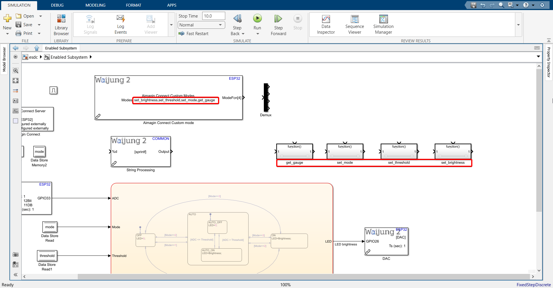
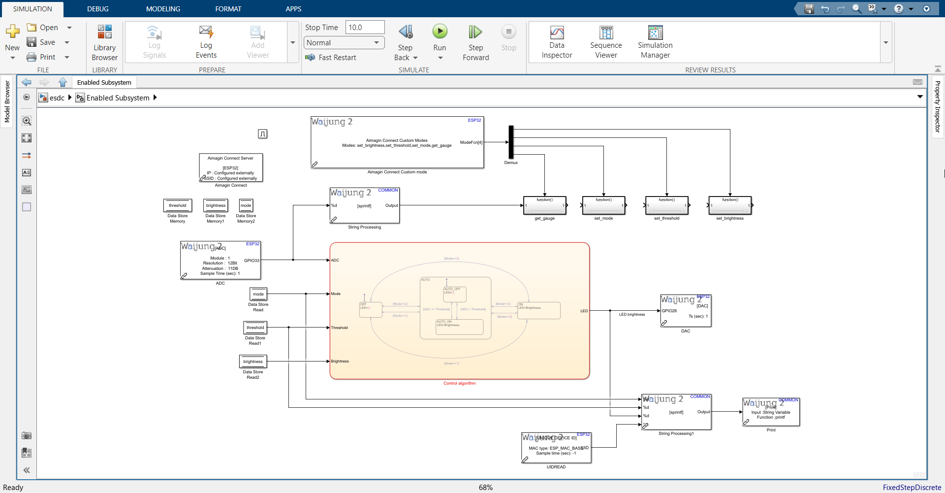
26. Connect all blocks as shown.
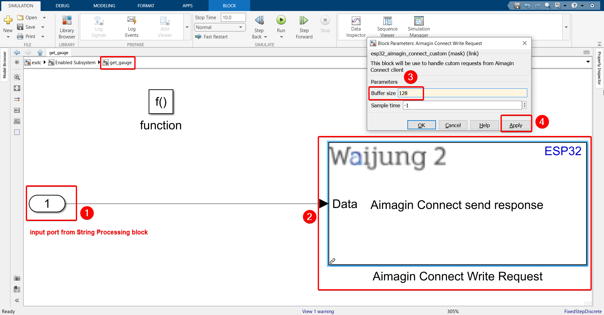
27. Enter the get_gauge function call subsystem, import the Aimagin Connect Write Request block, configure it and connect the input port coming from the String Processing block.
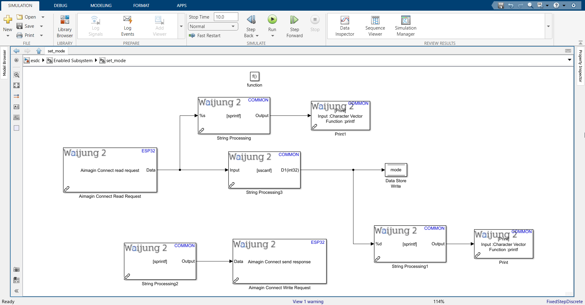
28. Enter the set_mode function call subsystem and import the following blocks.
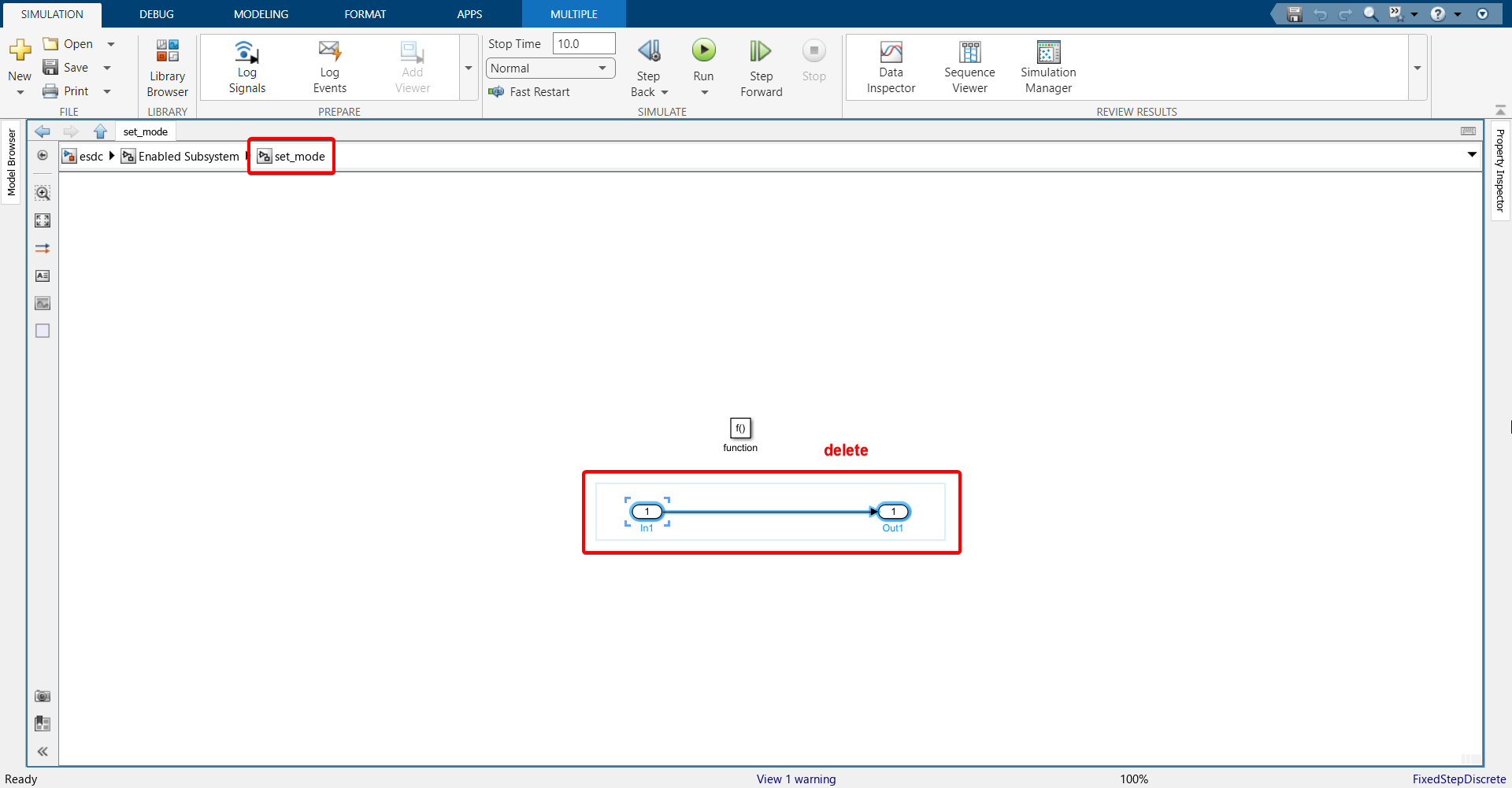
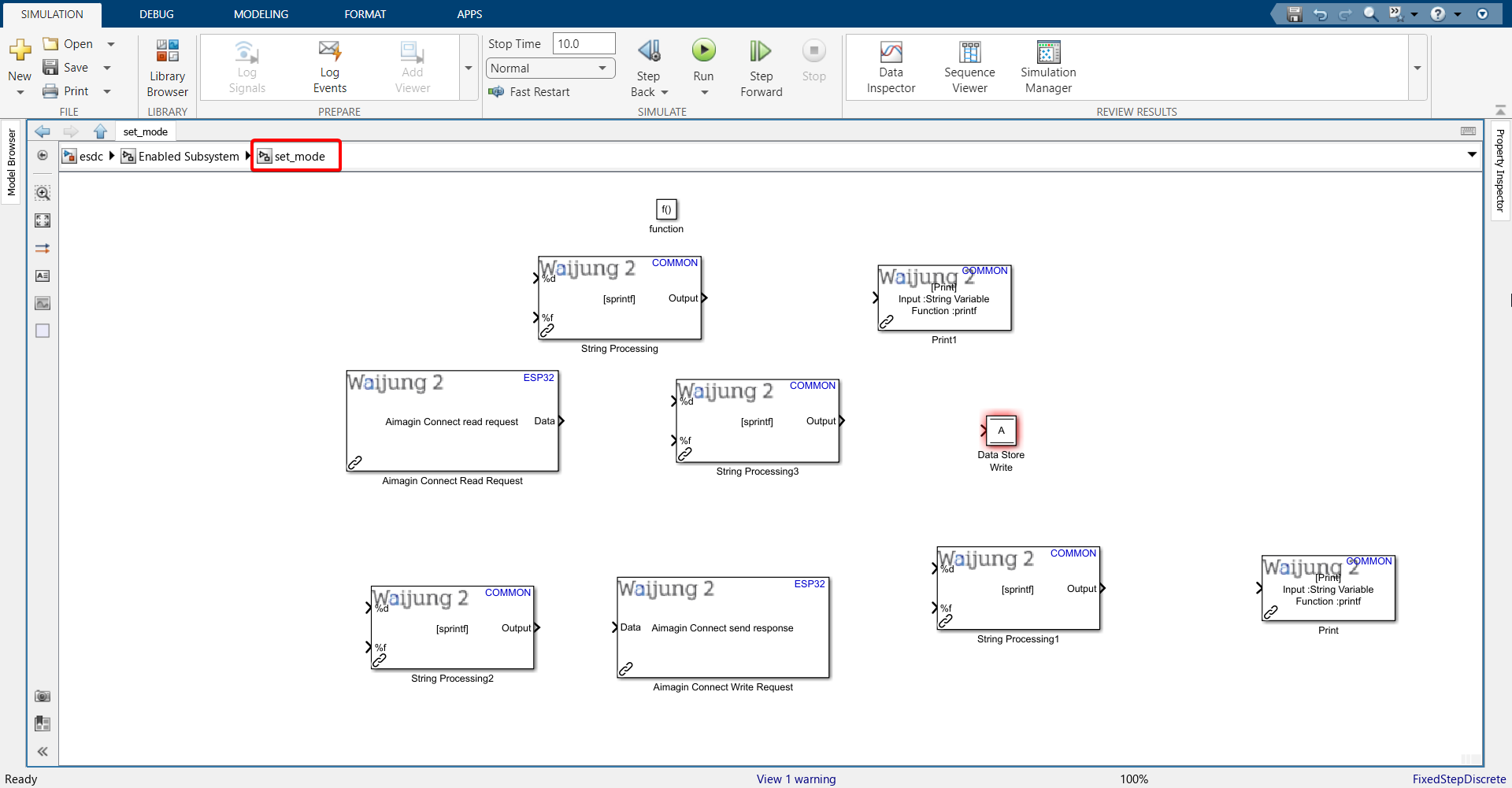
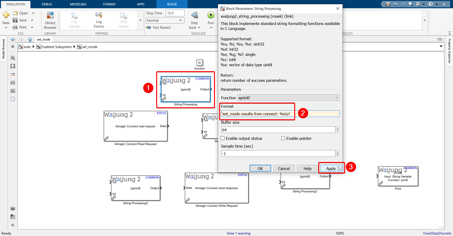
29. Configure the String Processing block.
Paste the following into the Format text field: 'set_mode results from connect: %s\n'
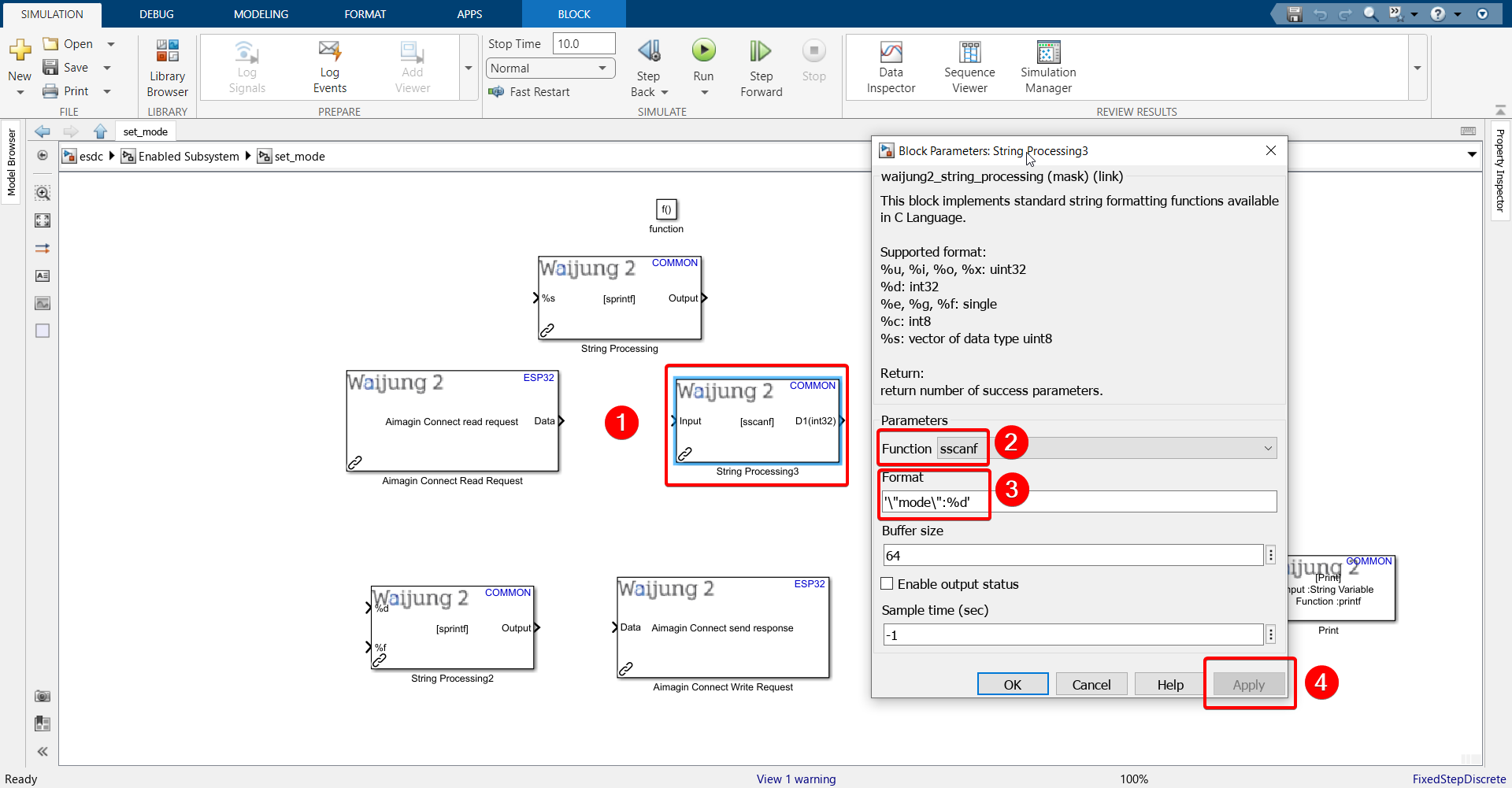
30.Configure the String Processing block.
Paste the following into the Format text field: '\"mode\":%d'
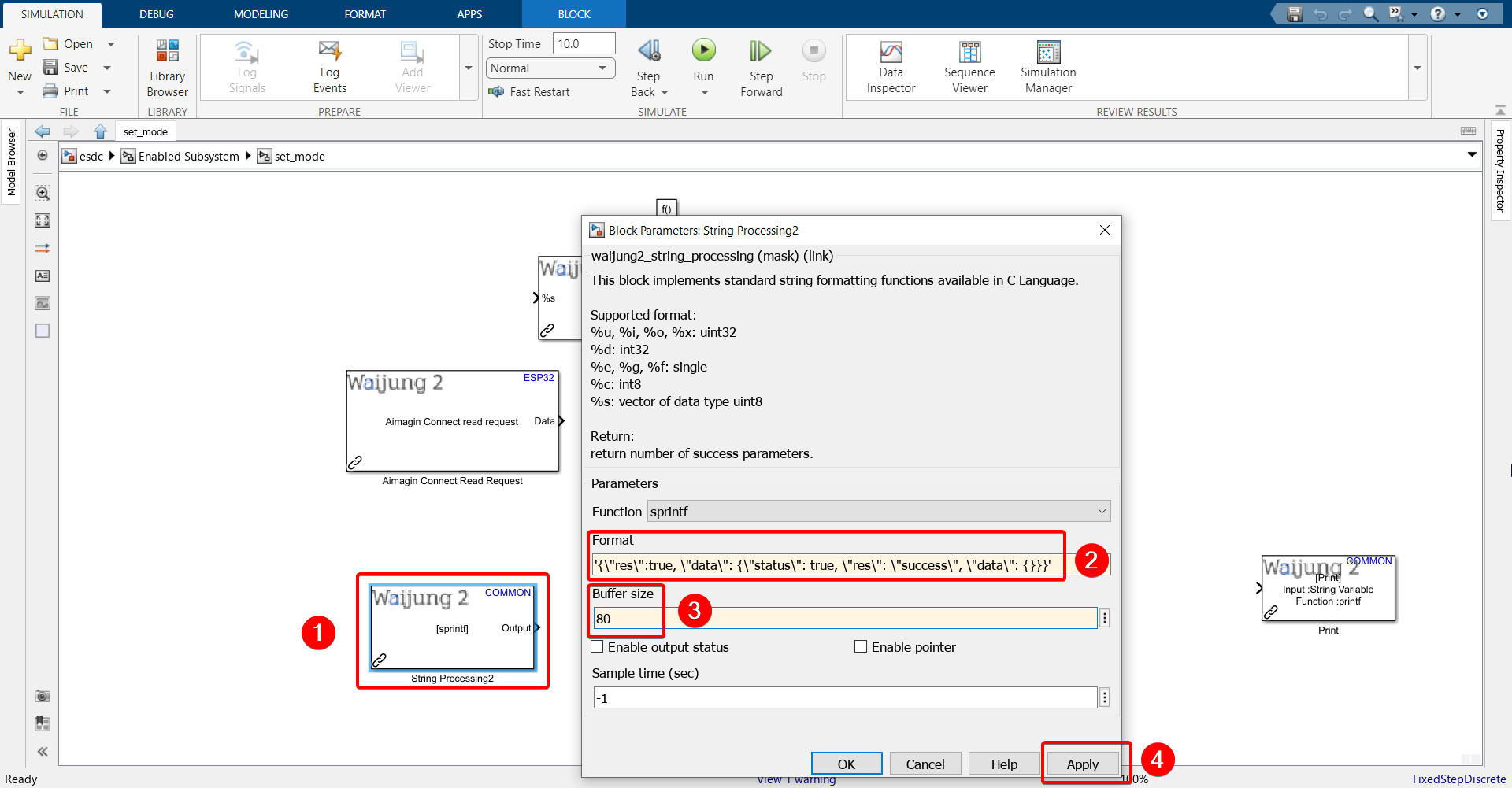
31.Configure the String Processing block.
Paste the following into the Format text field: '{\"res\":true, \"data\": {\"status\": true, \"res\": \"success\", \"data\": {}}}'
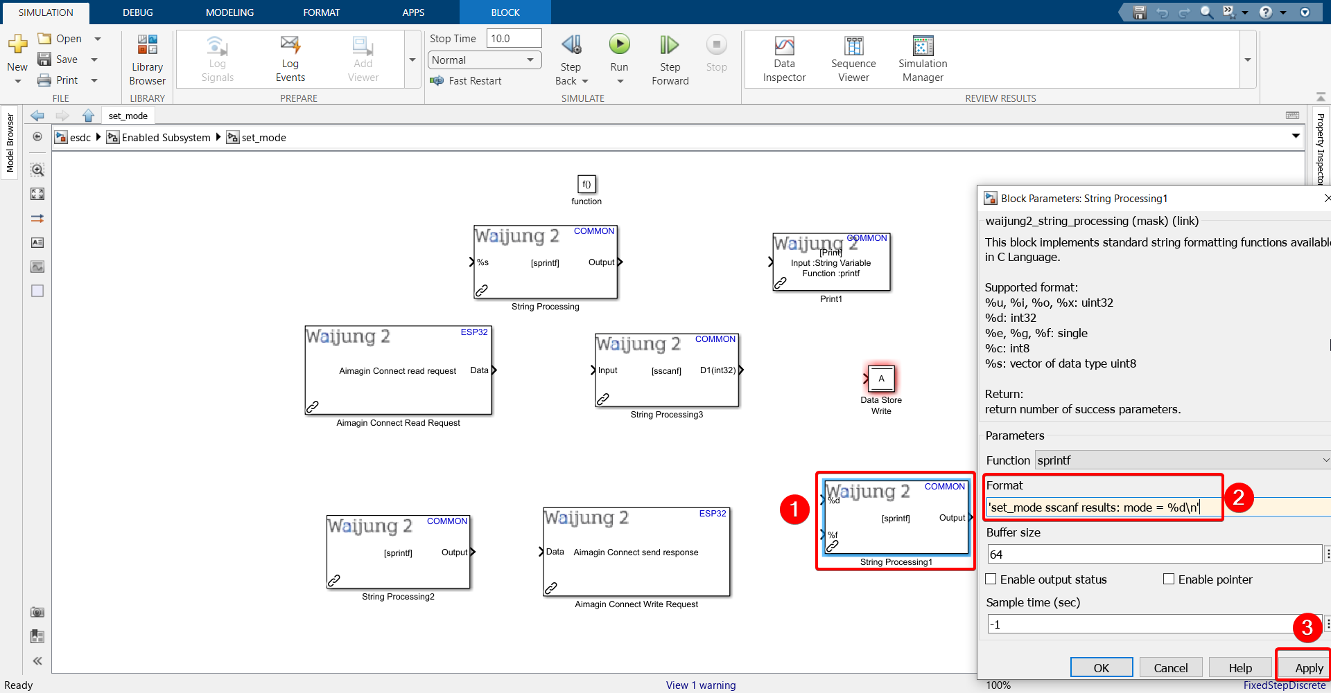
32.Configure the String Processing block.
Paste the following into the Format text field: 'set_mode sscanf results: mode = %d\n'
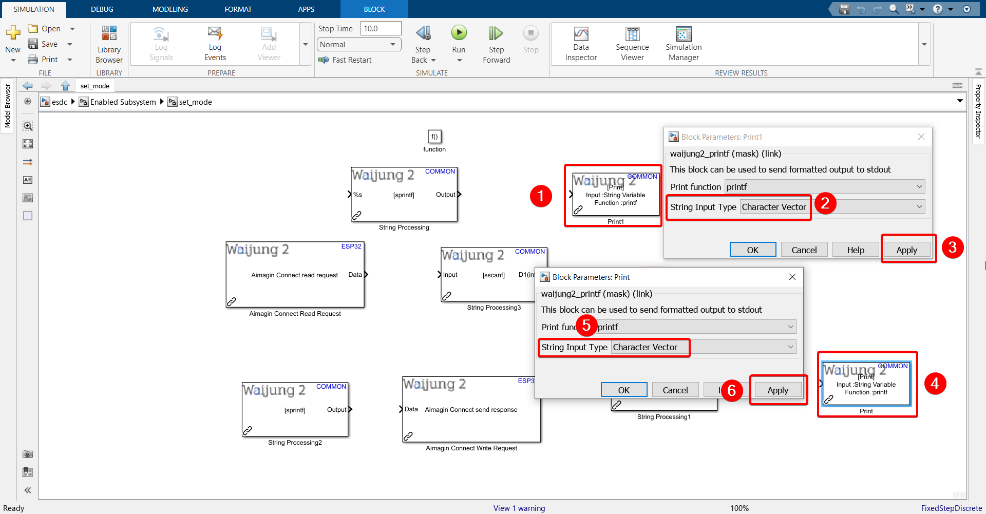
33. Configure both Print blocks.
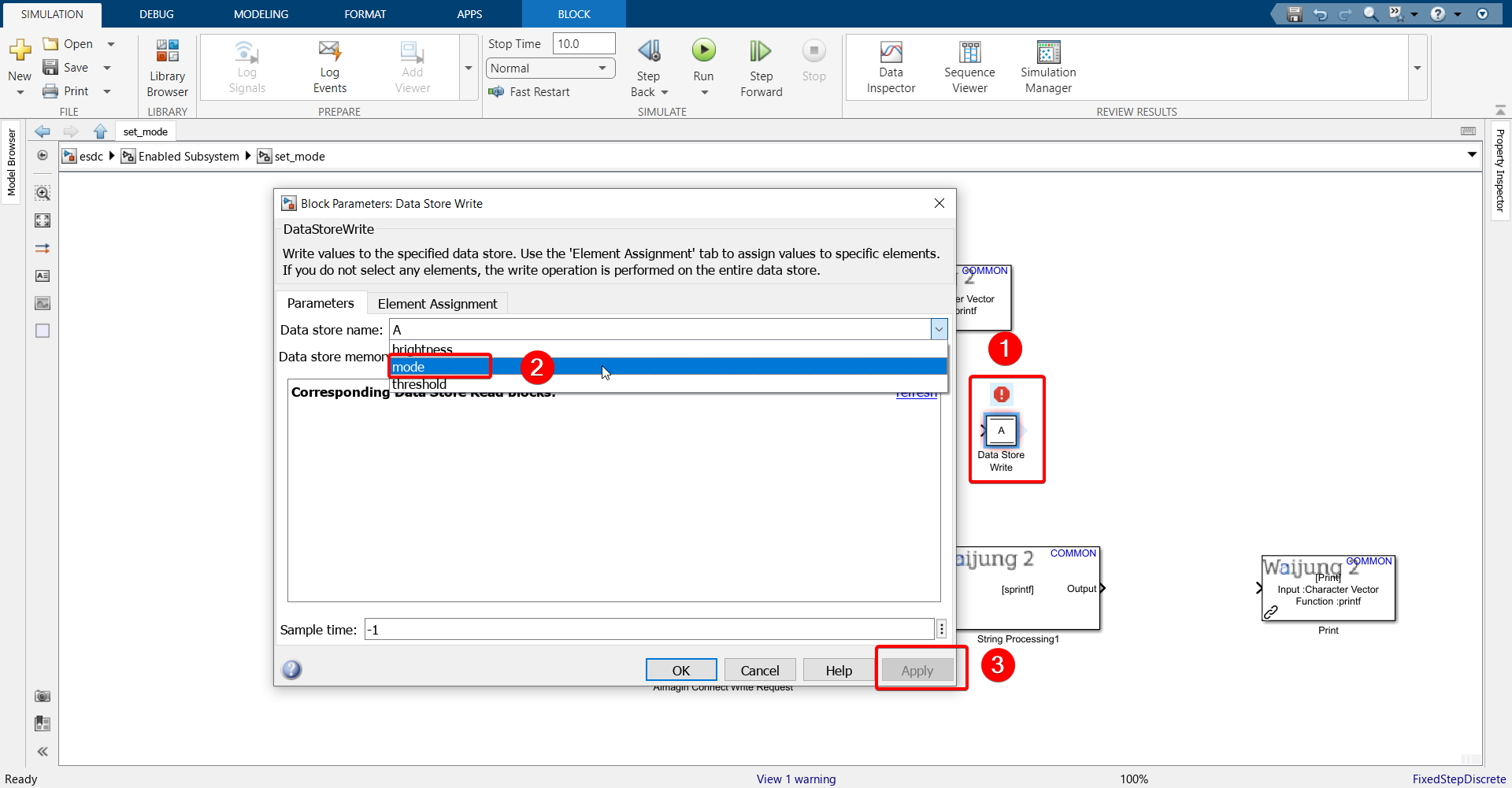
34. Configure Data Store Write block.
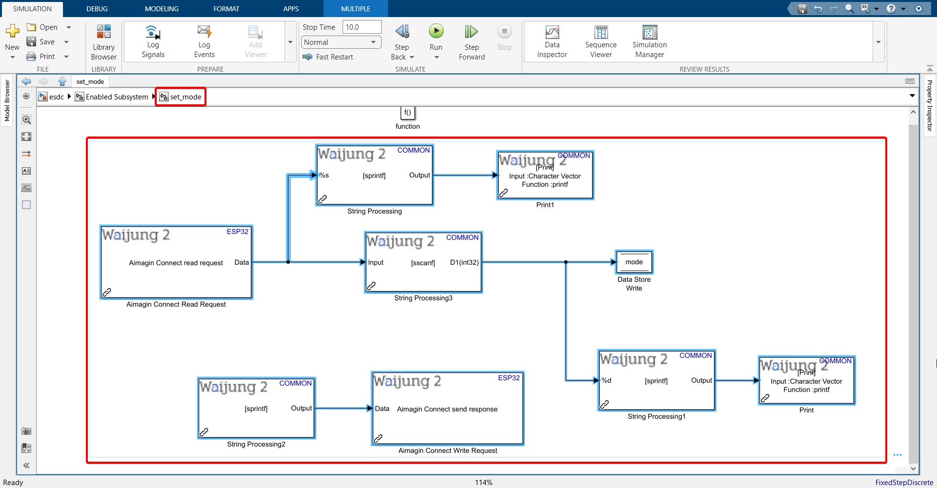
35. Connect all blocks as shown below.
36. Copy all the blocks (except function block) from set_mode subsystem, go to set_threshold subsystem and paste it there.
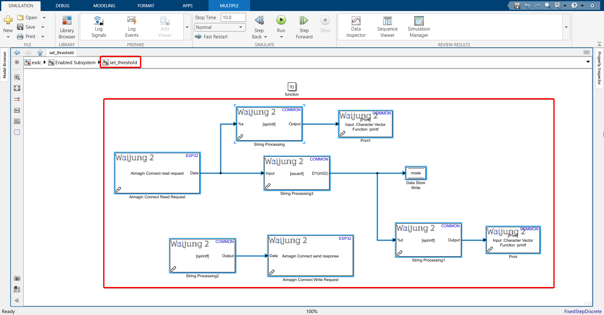
37. Repeat steps performed with the String Processing blocks in the set_mode function-call subsystem with some modifications:
'set_mode results from connect: %s\n' --> 'set_threshold results from connect: %s\n'
'\"mode\":%d' --> '\"threshold\":\"%u\"'
'set_mode sscanf results: mode = %d\n' --> 'set_threshold sscanf results: threshold = %d\n'
38. Change Data Store Write block from mode to threshold.

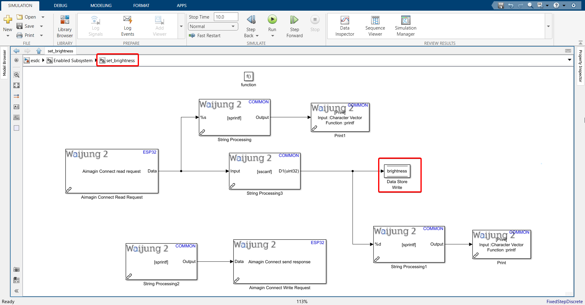
39. Copy all the blocks (except function block) from set_threshold subsystem, go to set_brightness subsystem and paste it there.
40. Repeat steps performed with the String Processing blocks in the set_threshold function-call subsystem with some modifications:
'set_threshold results from connect: %s\n' --> 'set_brightness results from connect: %s\n'
'\"threshold\":\"%u\"' --> '\"brightness\":\"%u\"'
'set_threshold sscanf results: threshold = %d\n' --> 'set_brightness sscanf results: brightness = %d\n'
41. Change Data Store Write block from threshold to brightness
42. Connect your ESP32 to your computer. After connecting, check the Waijung 2 Target Setup block to make sure the COM port selected is of the ESP32.
43. Make sure your SD card is also plugged into the ESP32.
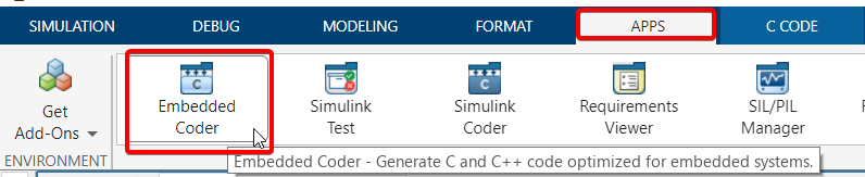
44.Go under ‘APPS’ and click ‘Embedded Coder’.
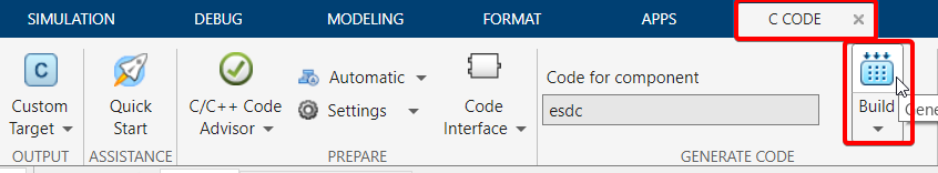
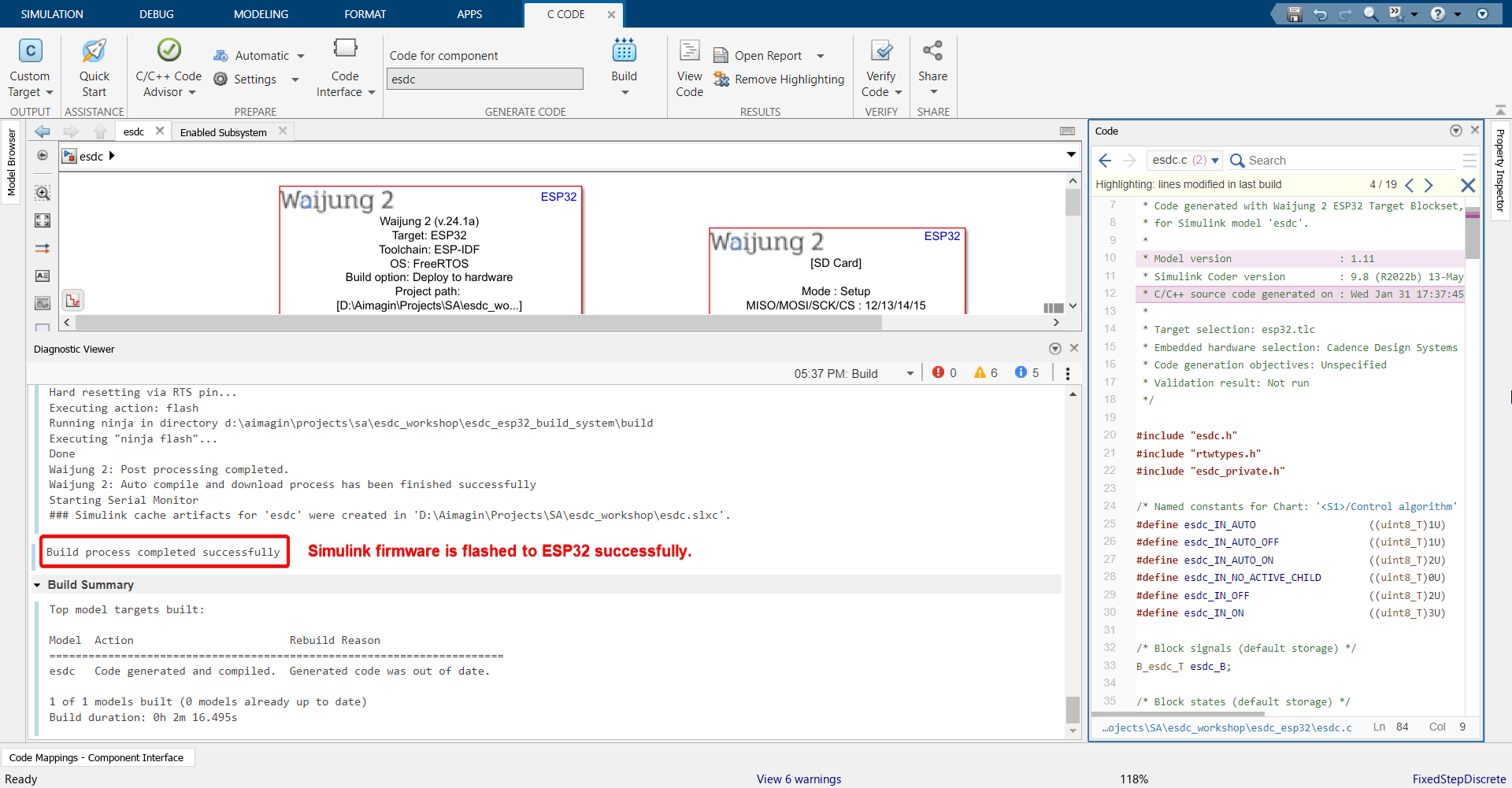
45. Click ‘Build’.
46. Once build is successful, serial monitor will open automatically. Copy the MAC address of your ESP32 shown in the serial monitor and store it somewhere. We will use this later.
47.Go to the IP address that you set in the WiFi Setup block and login with your credentials.
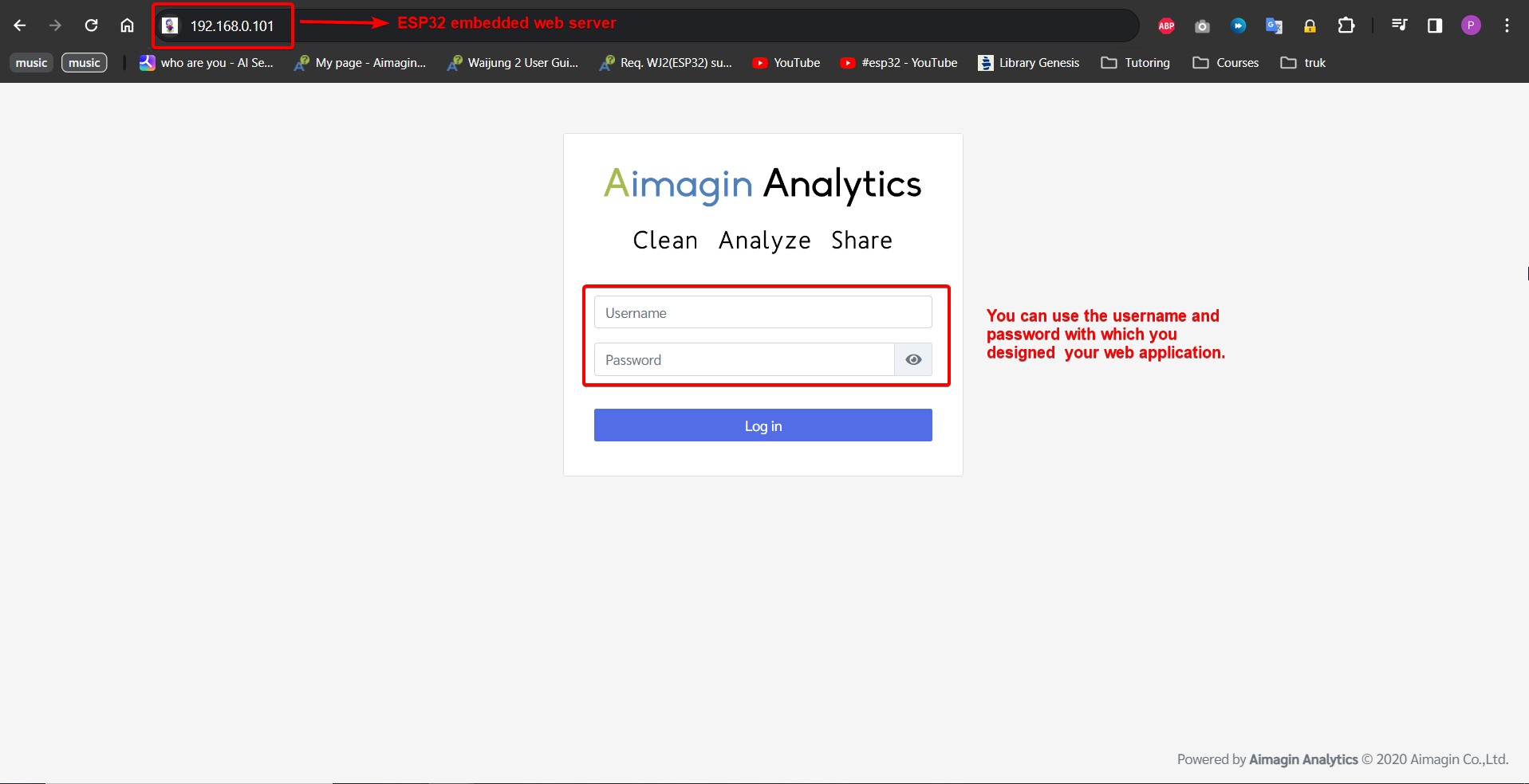
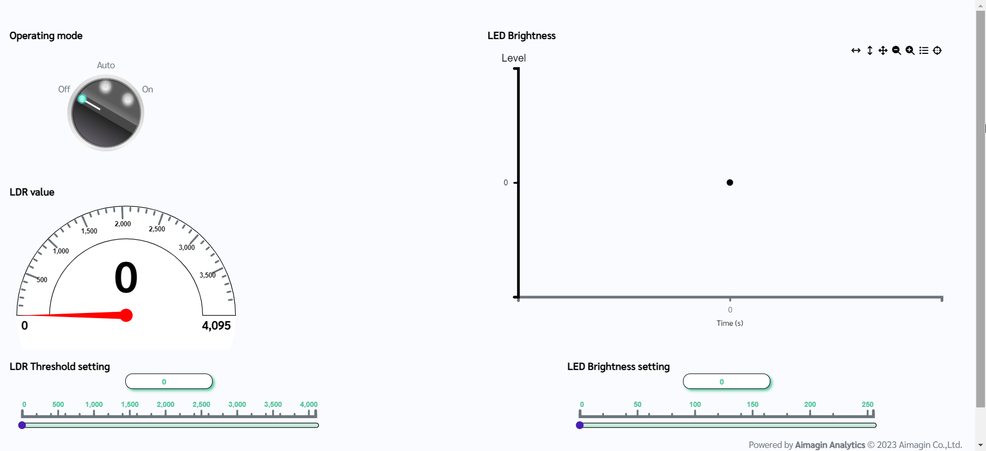
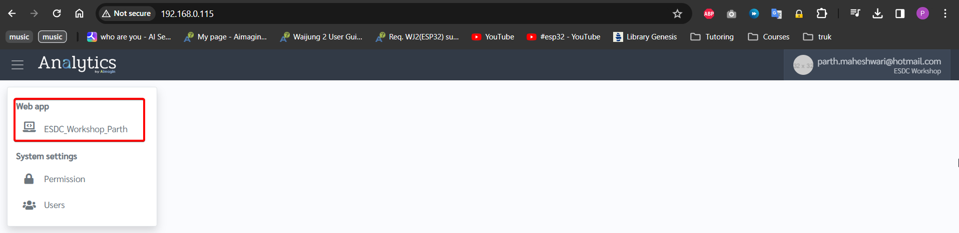
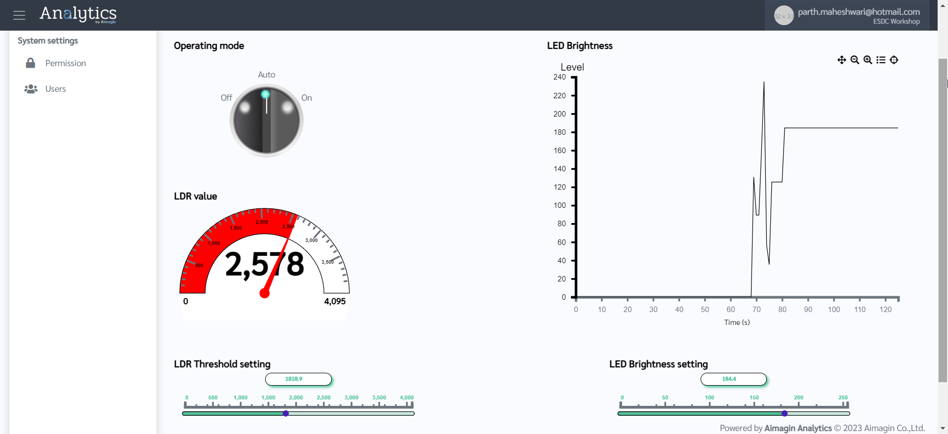
48. You will see your webapp published in the left menu bar. Click it to view your control interface. ESP32 is now acting as a stand-alone data acquisition device as well as a web-based controller. Enjoy playing around..
We have so far been able to design a web application using Aimagin Connect, which then runs in ESP32's embedded web server to both control ESP32 and acquire data from it simultaneously. Now we will move on to configuring the Aimagin Analytics server (Aimagin Connect is a part of Aimagin Analytics) such that it can receive data from ESP32 and store it.
PART 4: CONFIGURING AIMAGIN ANALYTICS SERVER
Note: To understand this section and the steps, it is important to understand what MQTT protocol is and how it works. We have tried to explain it as much as possible through the steps that will be shown but more background research will help you.
1.Go to https://bidev.aimagin.com/ and sign in to your Aimagin Analytics account using your credentials.
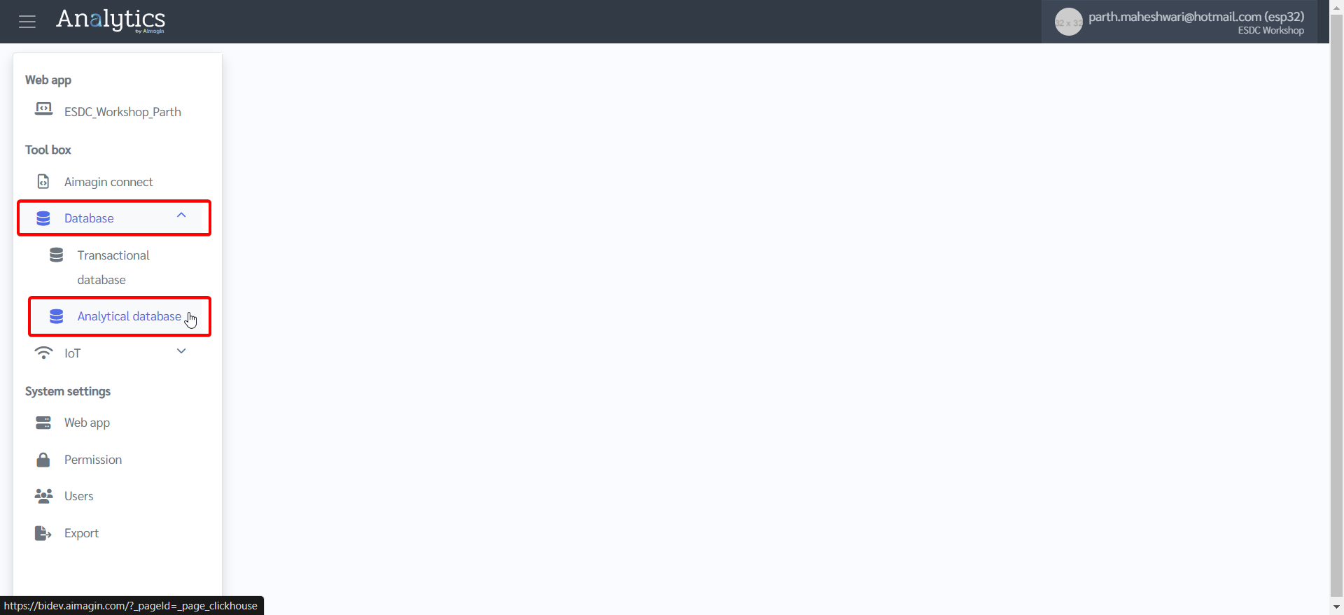
2.Create a new table under Analytical database.
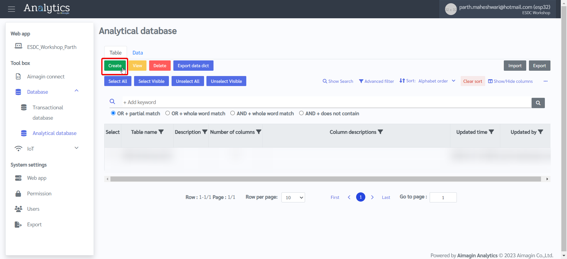
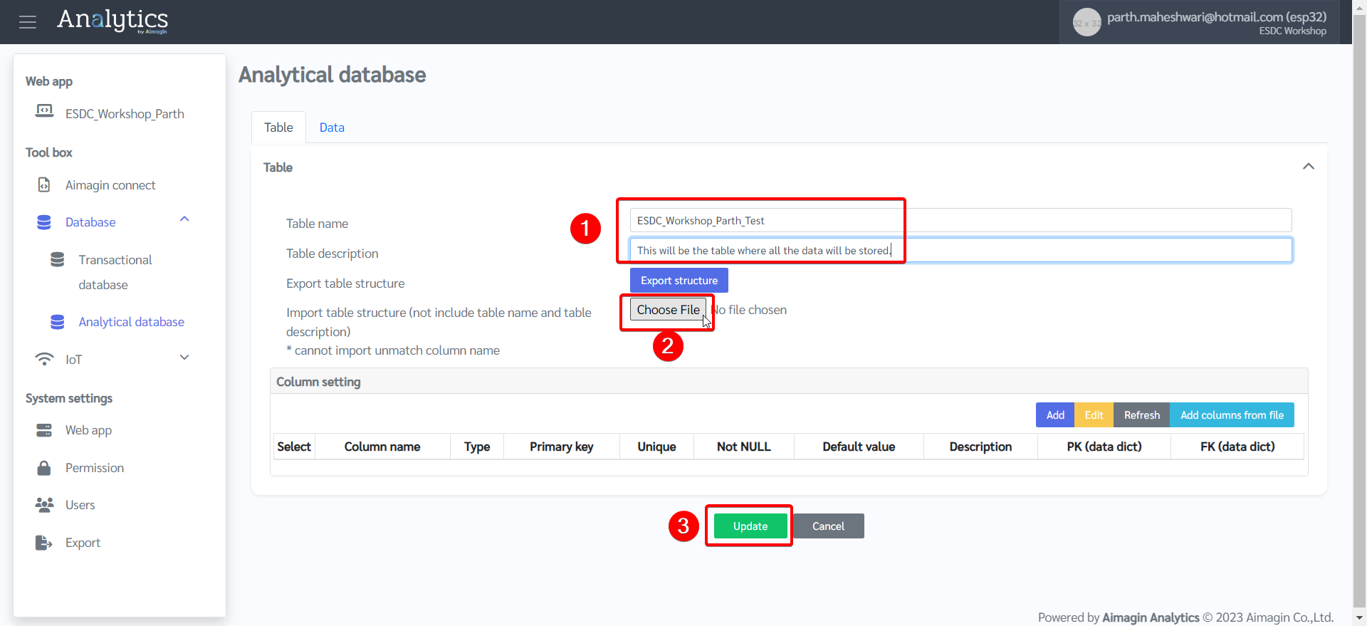
3.Give a name to the table, import this table structure file after downloading it, and create the table.
4.Create a topic to publish data to.
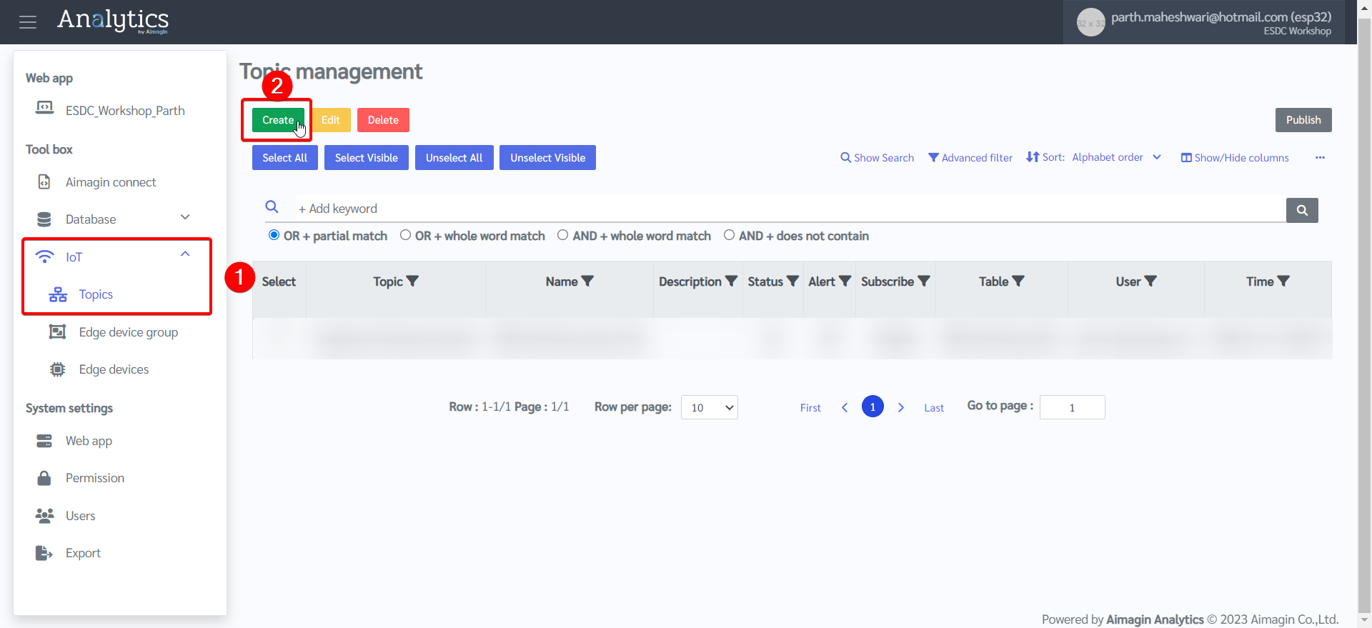
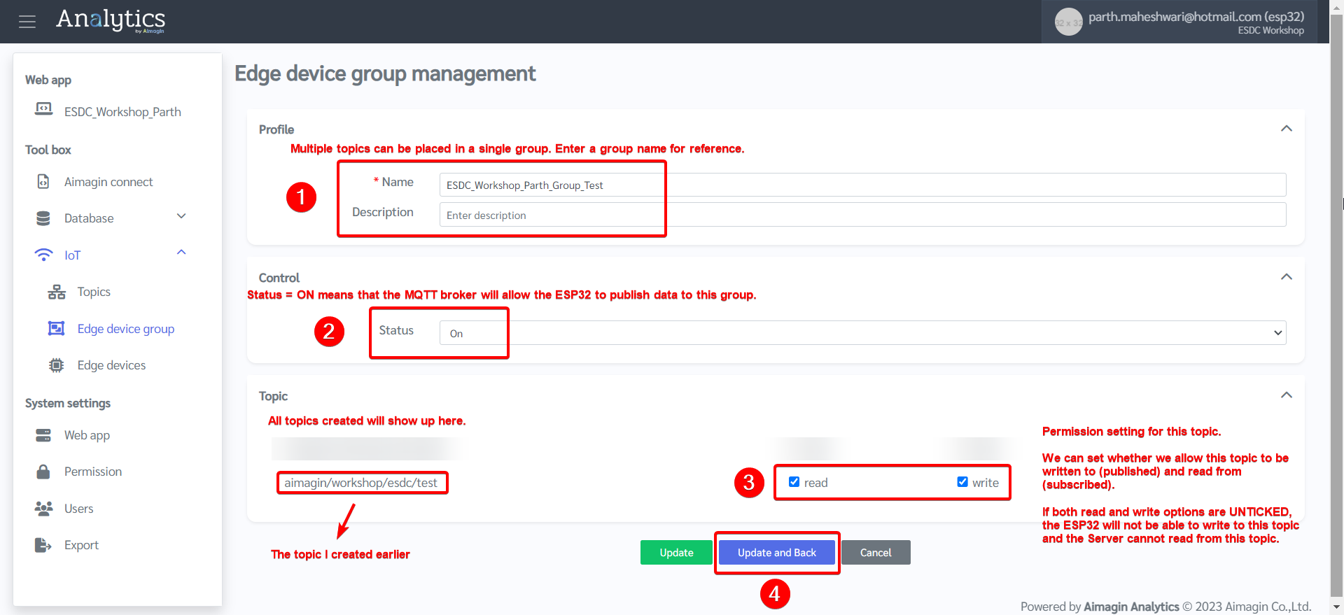
5.Set up the topic.
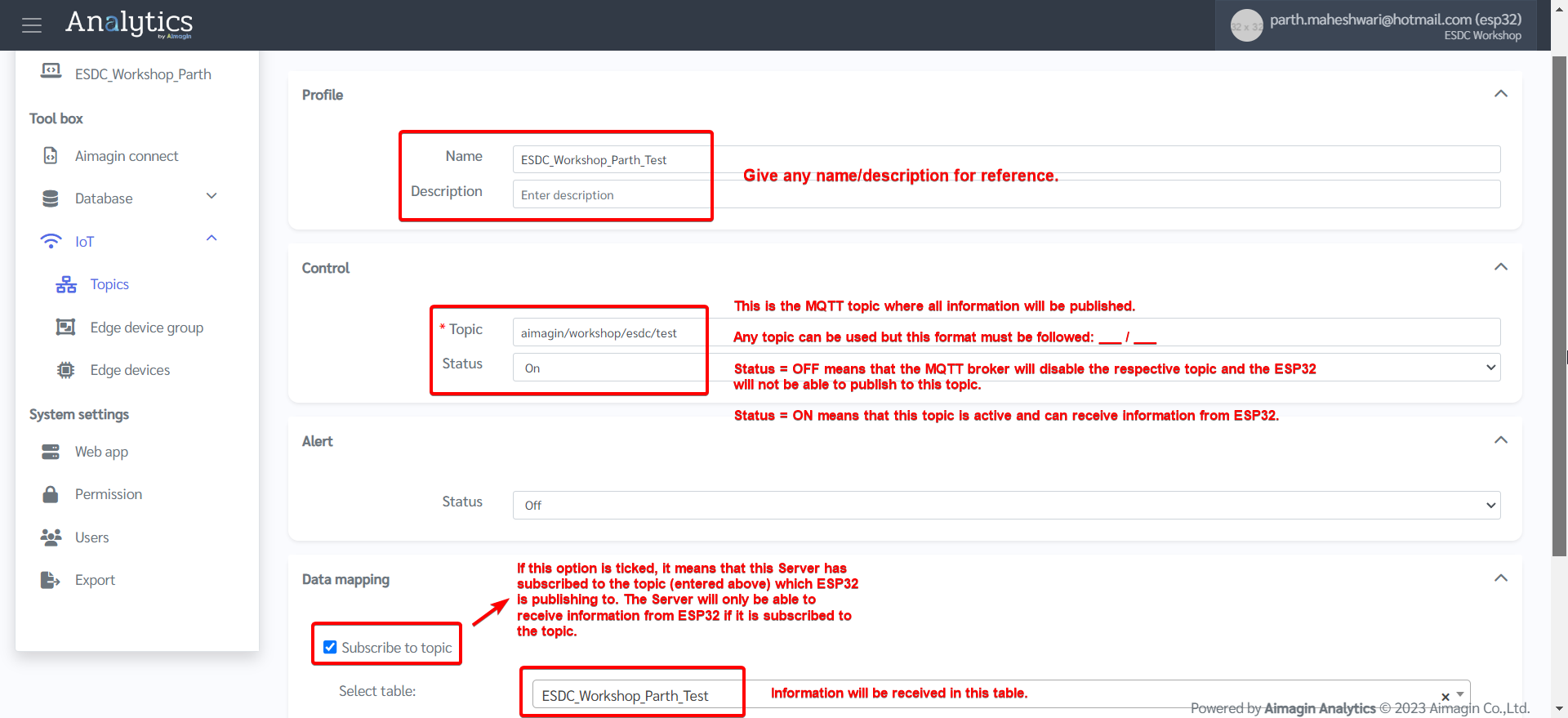
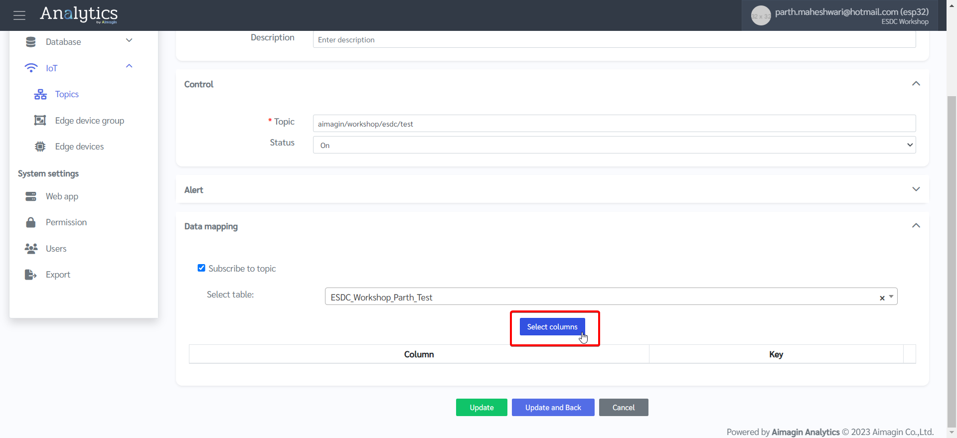
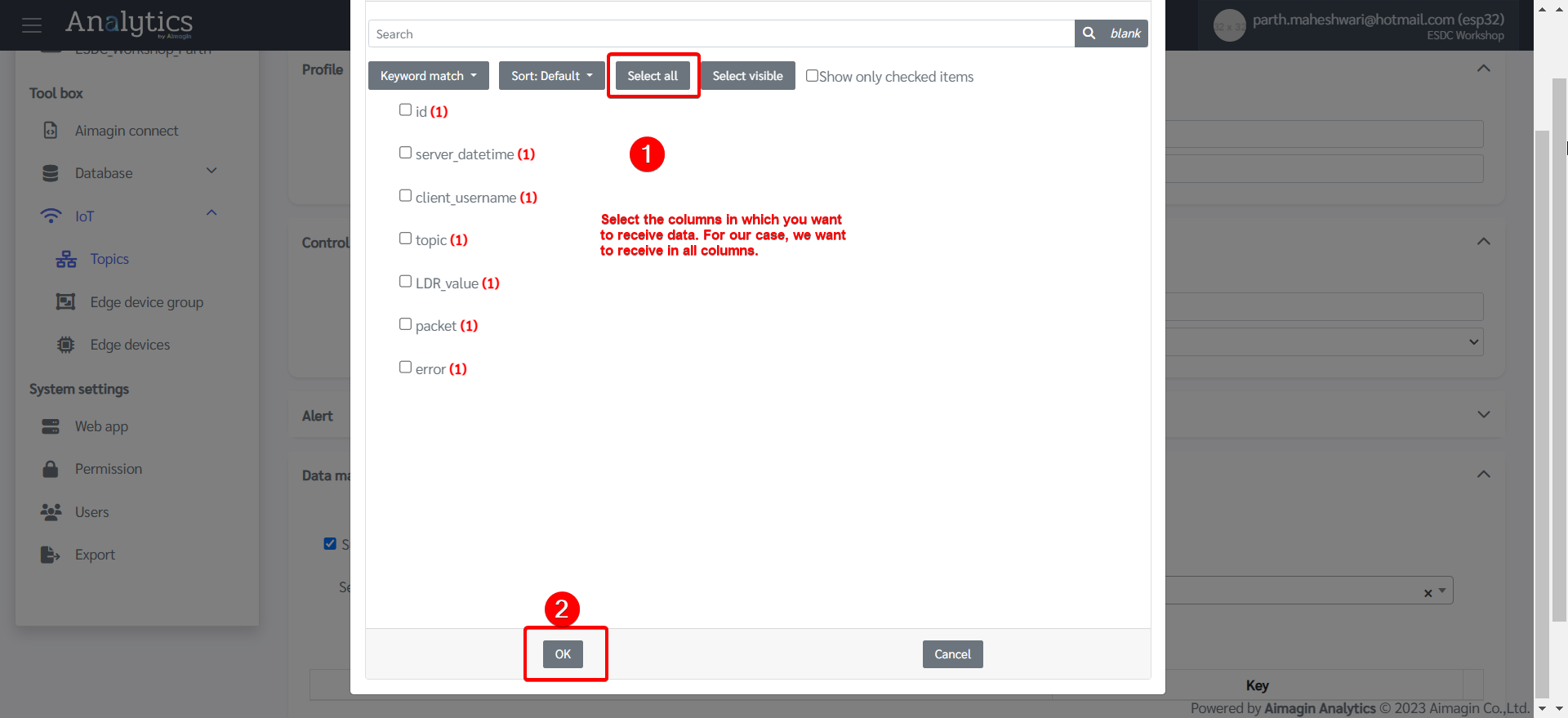
6.Do data mapping.
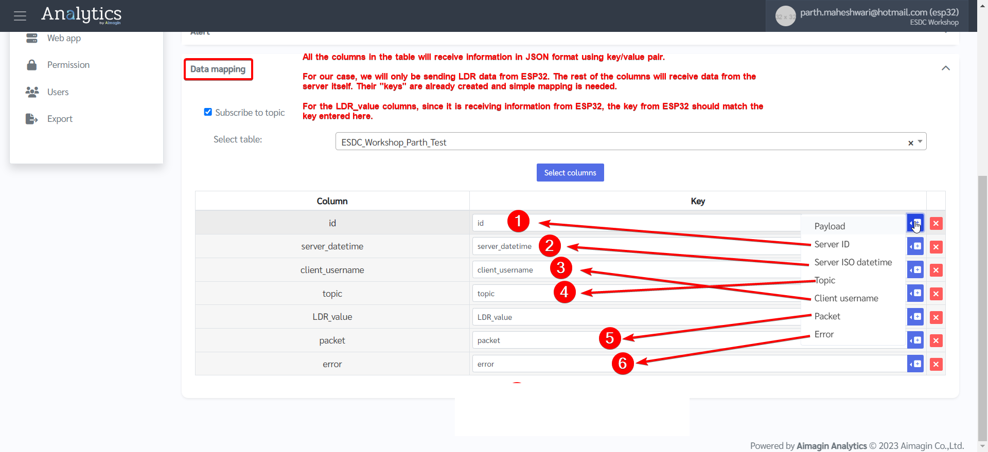
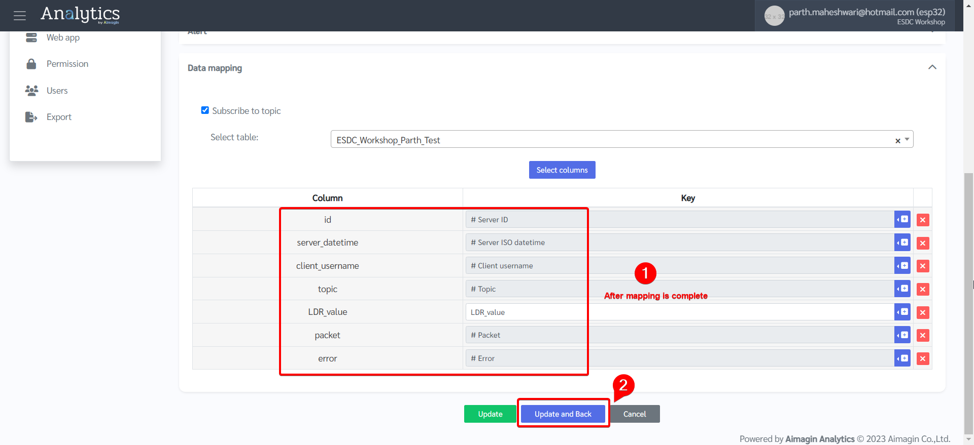
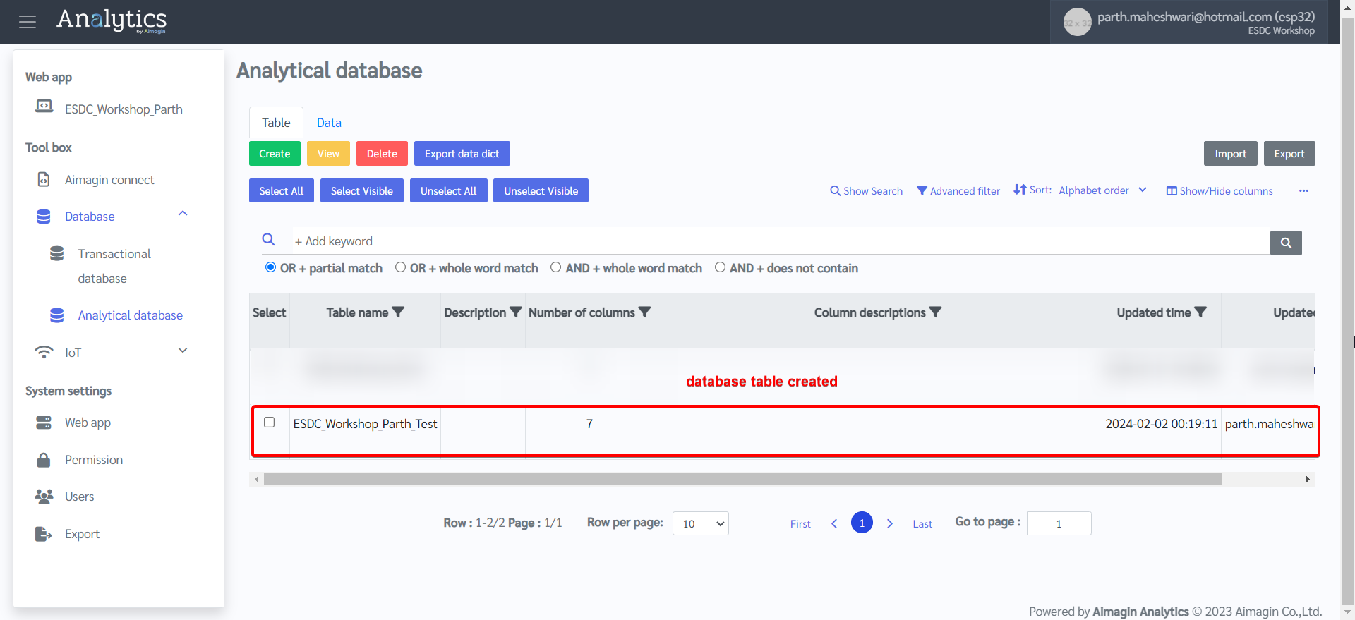
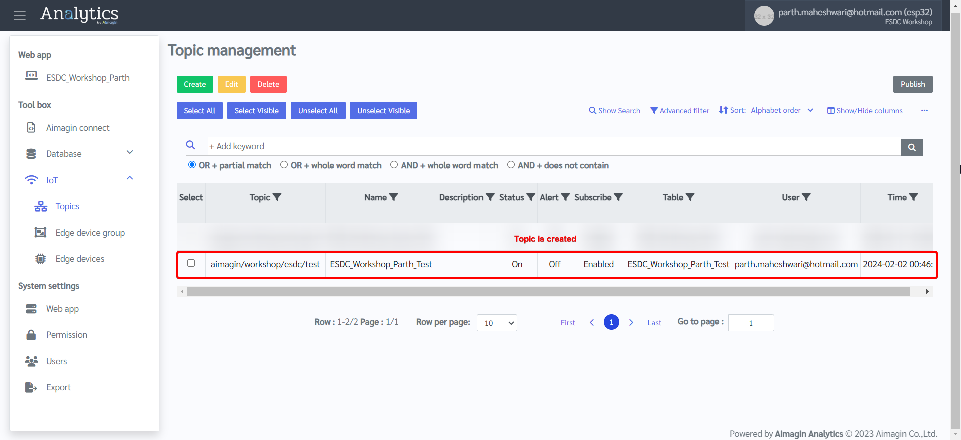
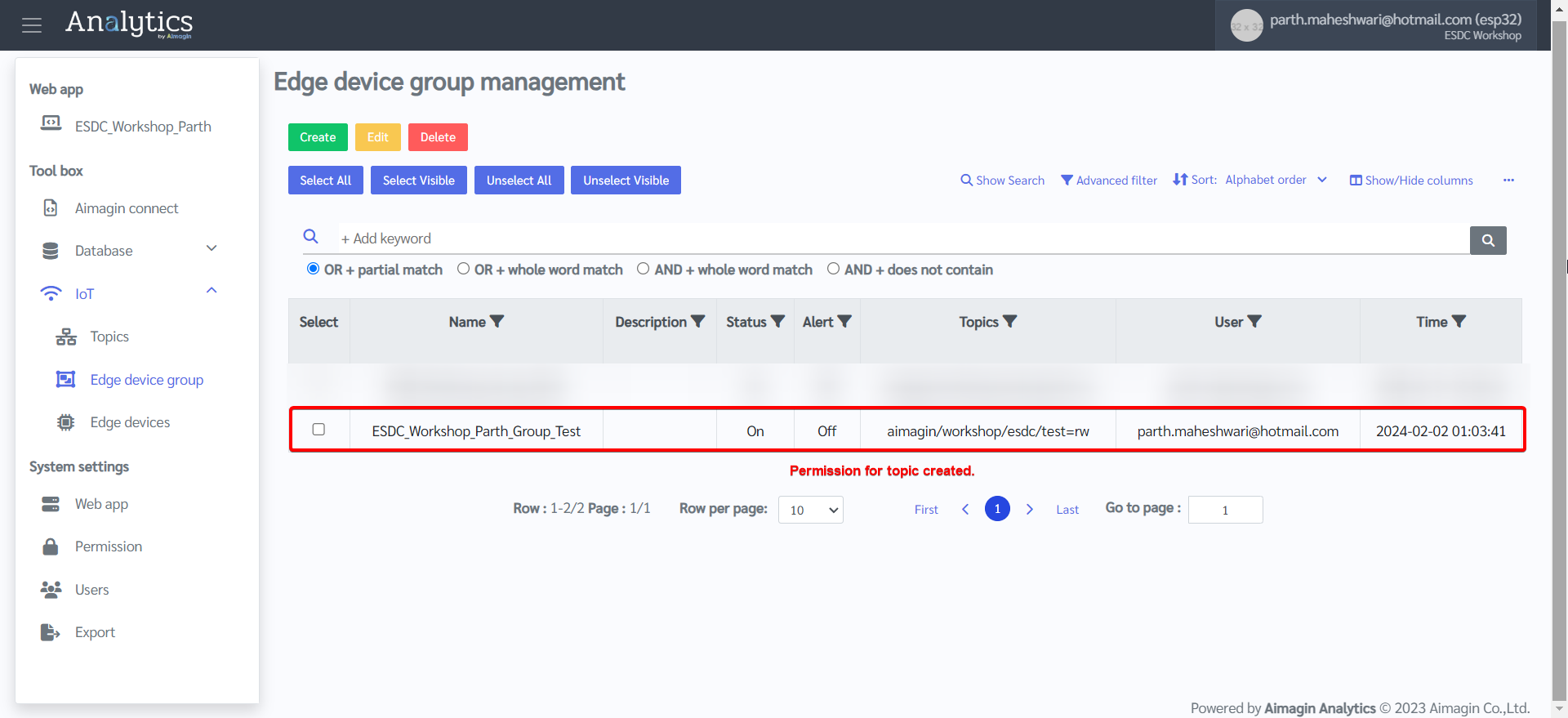
7.Topic is created.
8.Set permission for the topic created by going to Edge Device group.
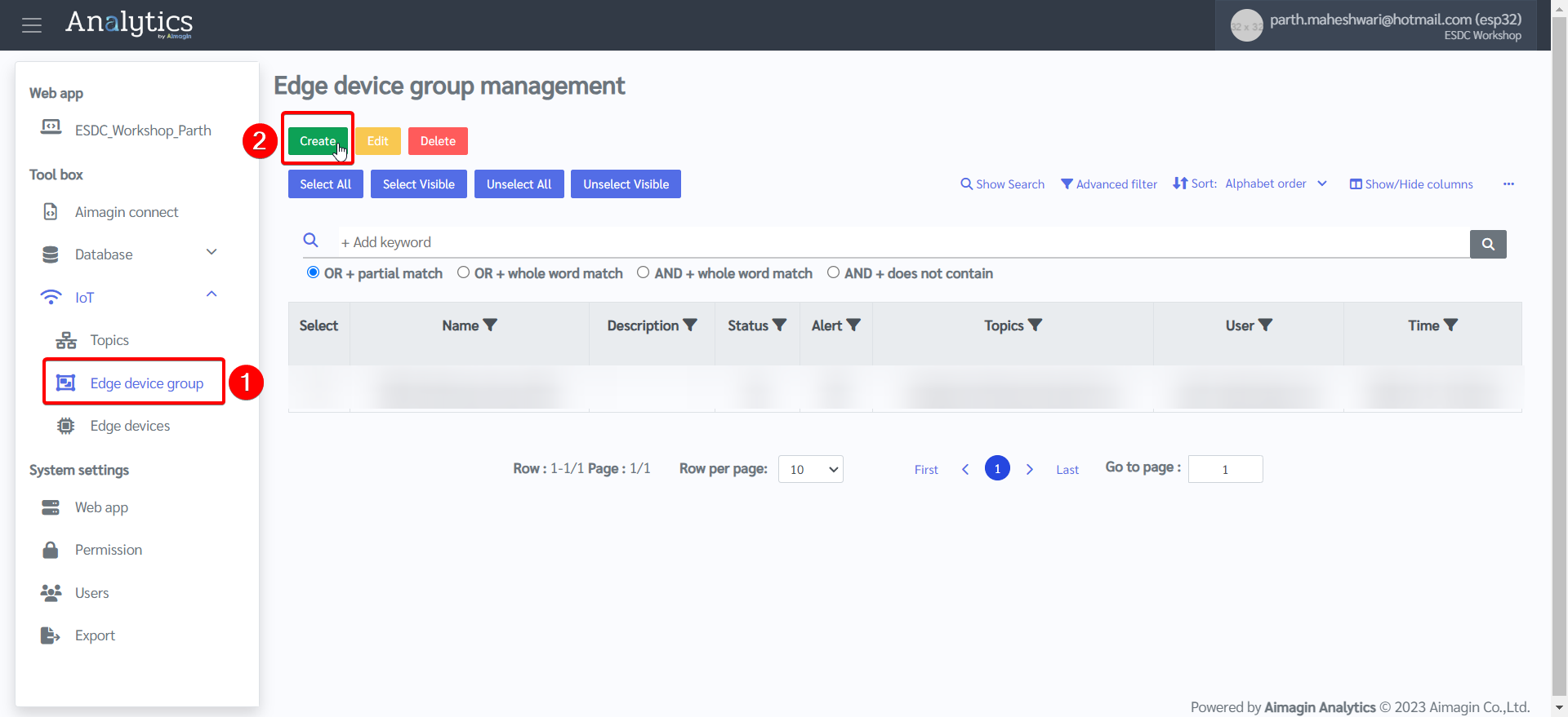
9.Create a new group and set permissions
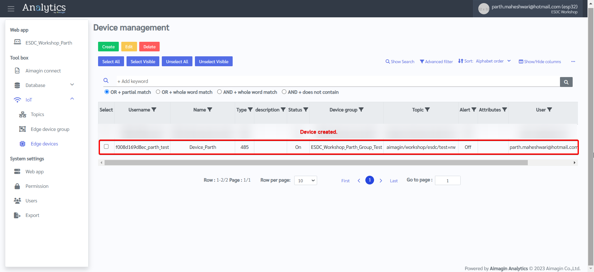
10. Register the device (ESP32) by going to Edge devices and creating a new device.
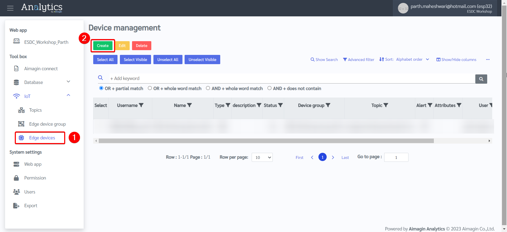
11. Enter device details. Enter the MAC address saved earlier. Create a username and password and save it, you will need this later.
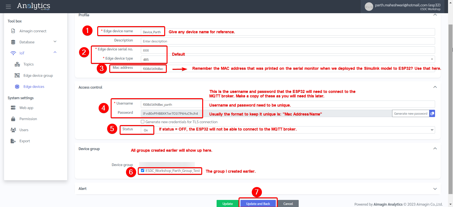
12. Device created.
Server configuration is now complete. The Aimagin Analytics Server includes the MQTT broker and also acts as a Client by subscribing to the topic the ESP32 (also a Client) will be sending information to. A lot of the information entered in this section to configure the server to receive information will be used in the next section, which will also be the final section of this project.
PART 5: DESIGN FIRMWARE ON MATLAB/SIMULINK (PART B)
Note: You can download the completed file here, or you can follow the steps and do it yourself as well.
We will be adding a few blocks to the Simulink model designed in Part 3 of this project. These blocks will be related to adding MQTT functionality to the model so that the ESP32 can communicate with the server and send data.
1.Open the model saved in Part 3 of this project.
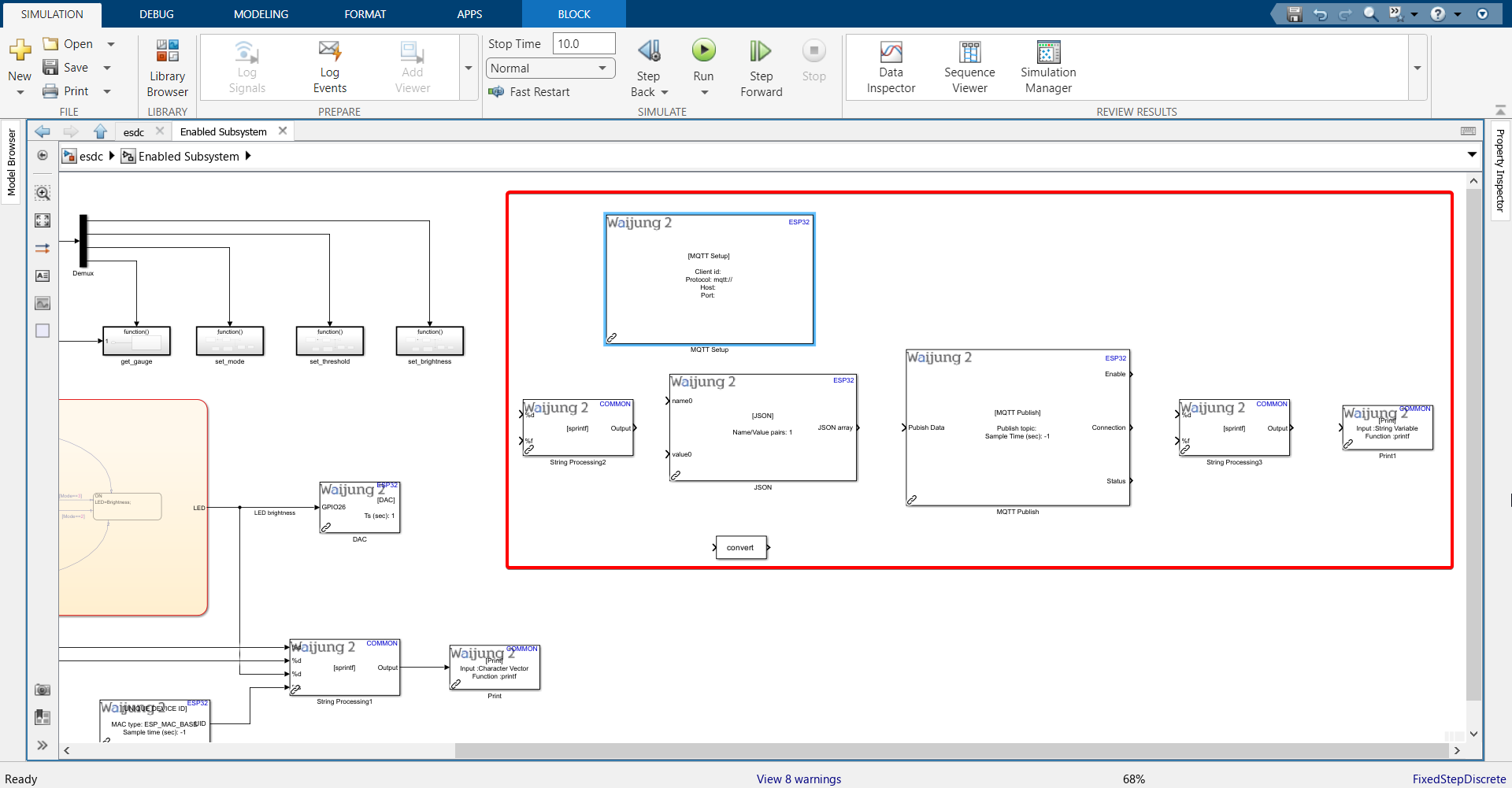
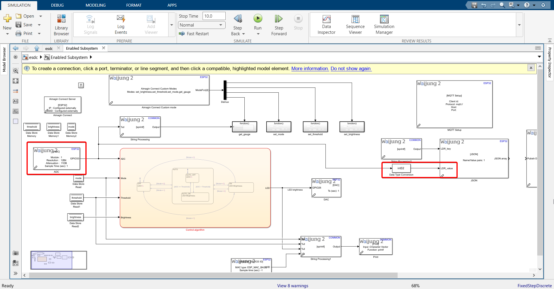
2.Import the blocks shown. Block names are below each block. To import the 'convert' block, search for 'Data Type Conversion'.
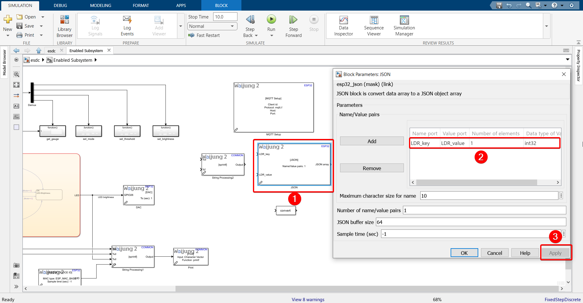
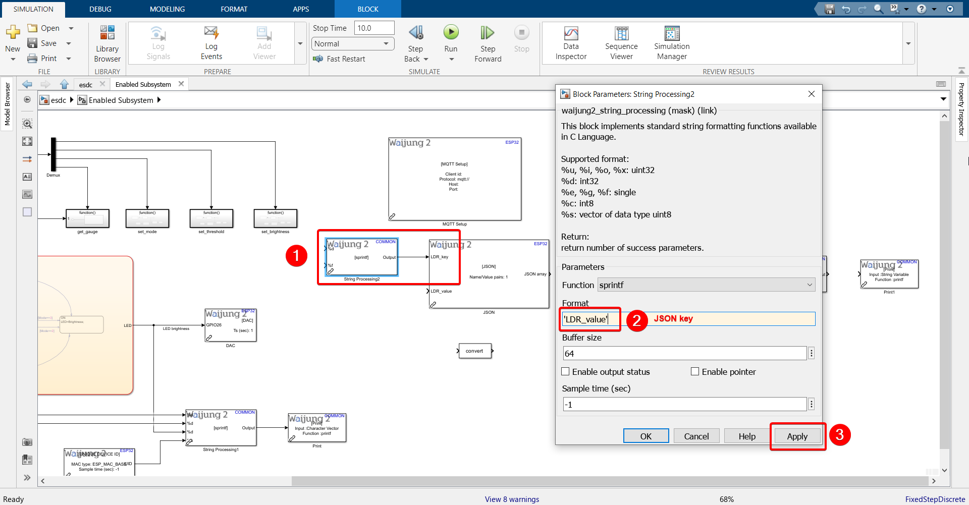
3.Refer back to this step of configuring the server. Recall that out of the 7 columns in our database table, 6 of them will be updated with information coming from the server. It is only the LDR value that will be sent from the ESP32. We need to send the LDR value in JSON format, and we have defined the "key" on the server as 'LDR_value'. The key entered here should match the key sent from ESP32.
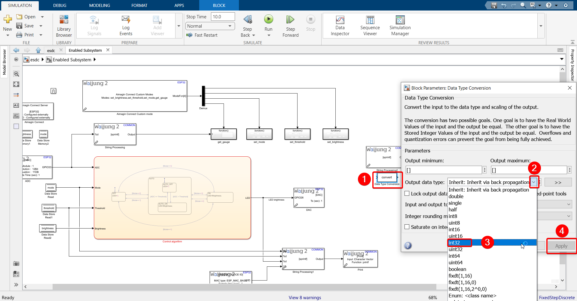
4.Double click the JSON block and configure as shown. We are configuring the data type column to be int32 because the LDR value this block receives will be from the ADC block, which will output values between 0 and 4095, making it an int32 type.
5.Enter the JSON key in String Processing block and connect to JSON block.
6.Double click the Data Type Conversion block and change it to int32 type.
7.Connect ADC block output to it and then connect that to JSON block.
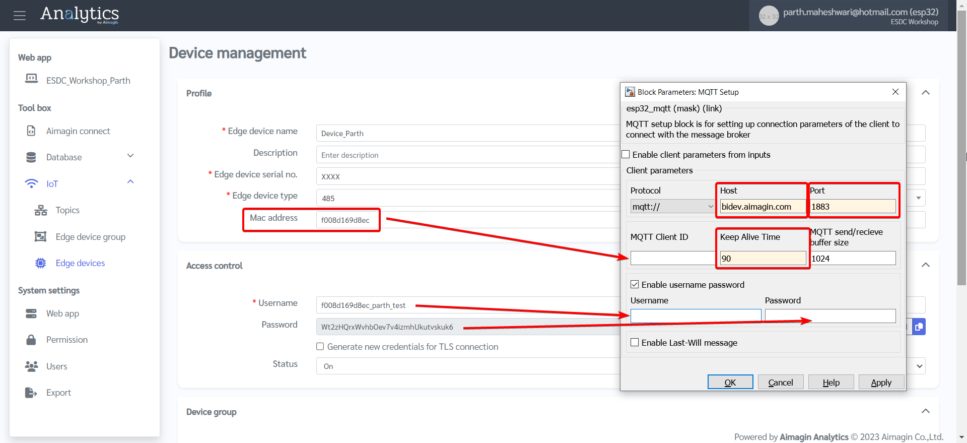
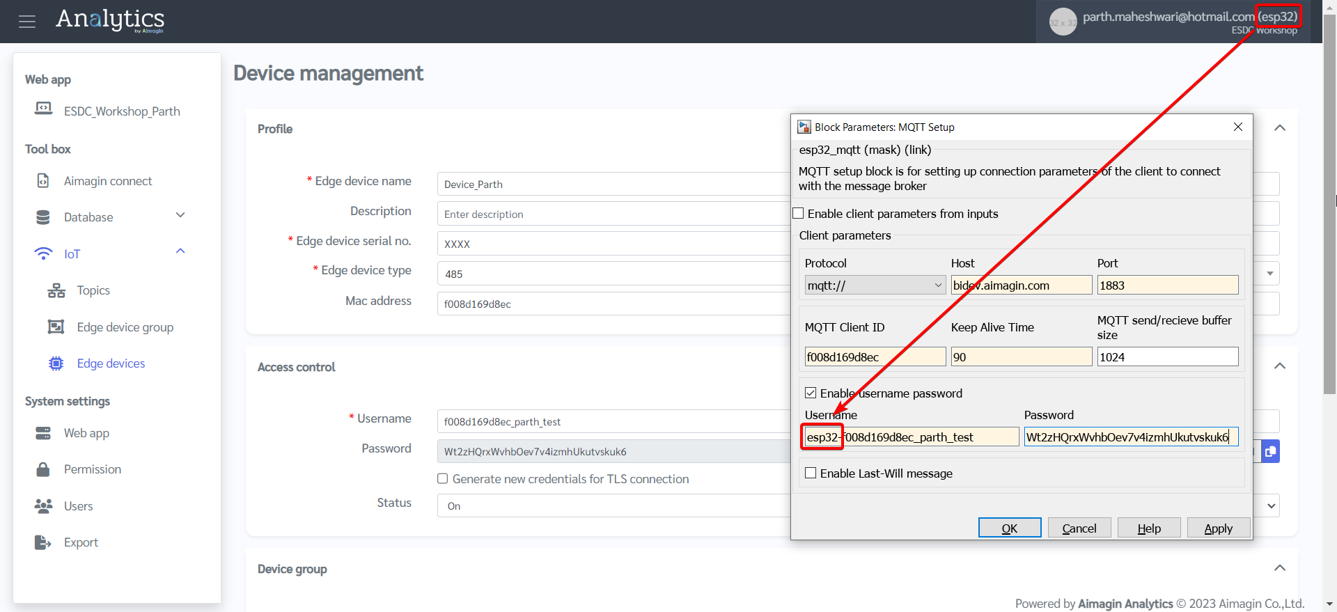
8.Double click MQTT Setup block and configure according to information entered in the server under Edge Devices.
Host: bidev.aimagin.com
Port: 1883
MQTT Client ID: MAC address of ESP32
Keep Alive Time: 90
Username: Need to add "esp32-" before adding username.
Password: If you haven't noted down the password when you were first setting up the Edge Device page, you will need to generate a new password. Make sure to update the Edge Device page after you generate a new password and copy that to the Password field in the MQTT Setup block.
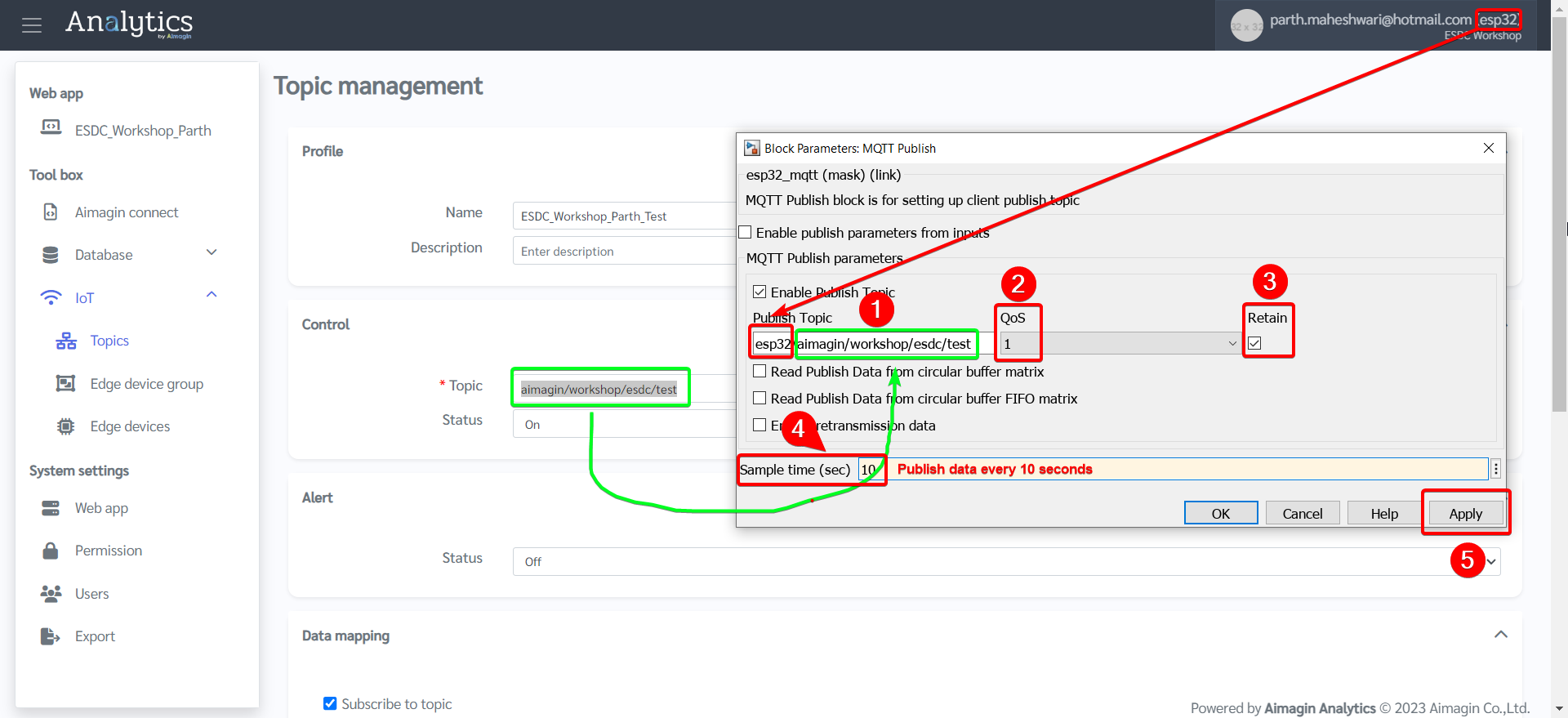
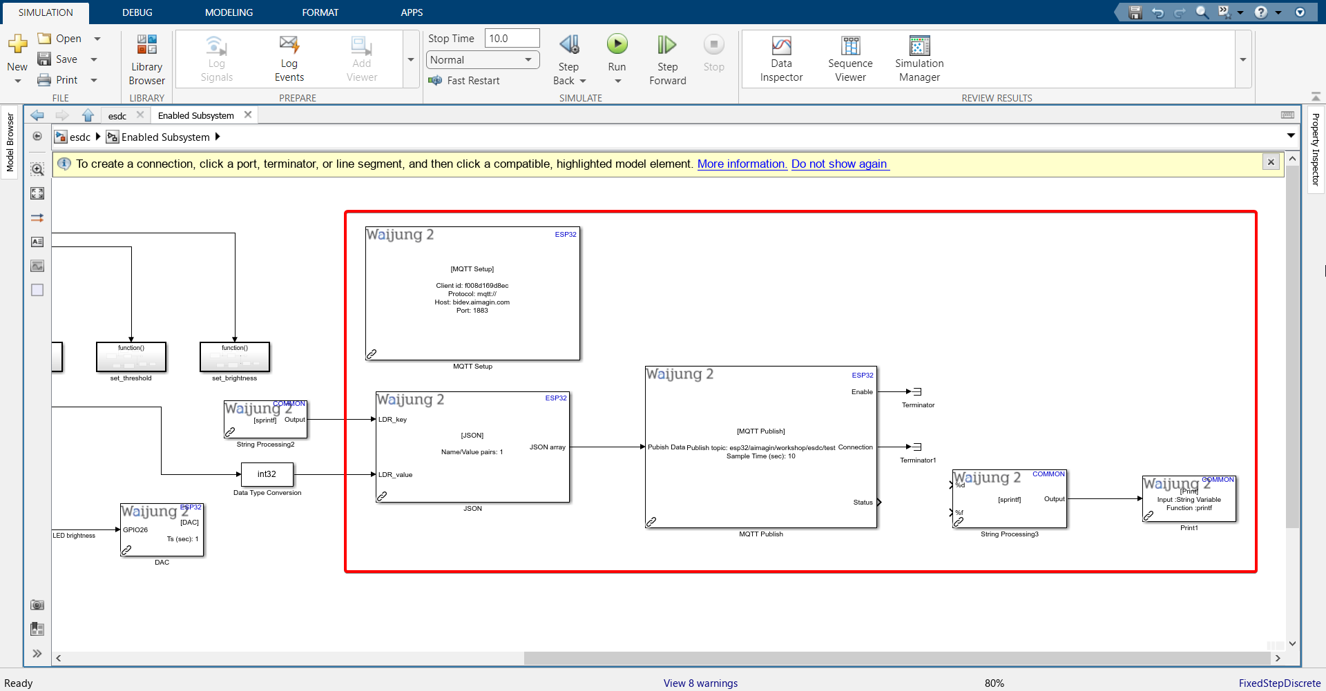
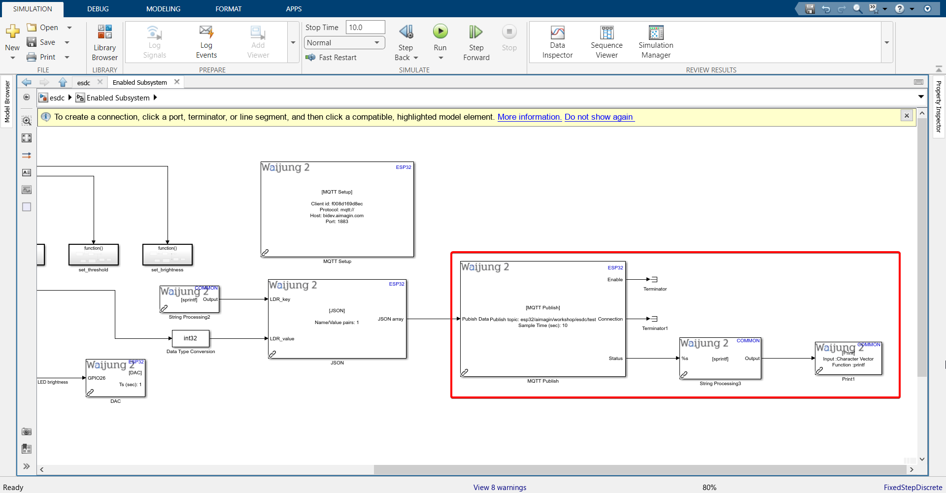
9.Double click MQTT Publish block and configure according to information entered in the server under Topics. We will be publishing data to server every 10 seconds.
10. Connect blocks as shown.
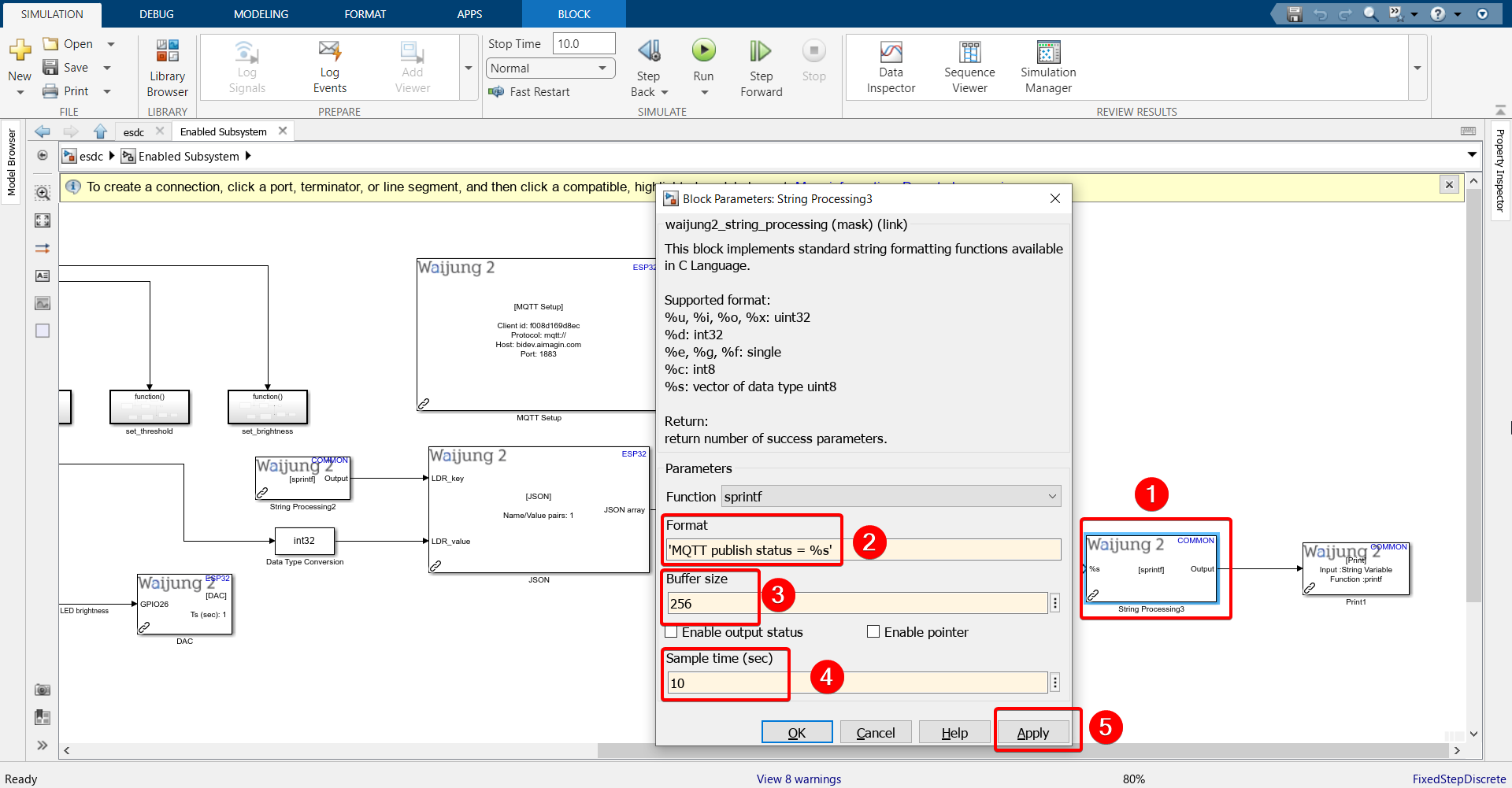
11. Configure String Processing block.
Format: 'MQTT publish status = %s'
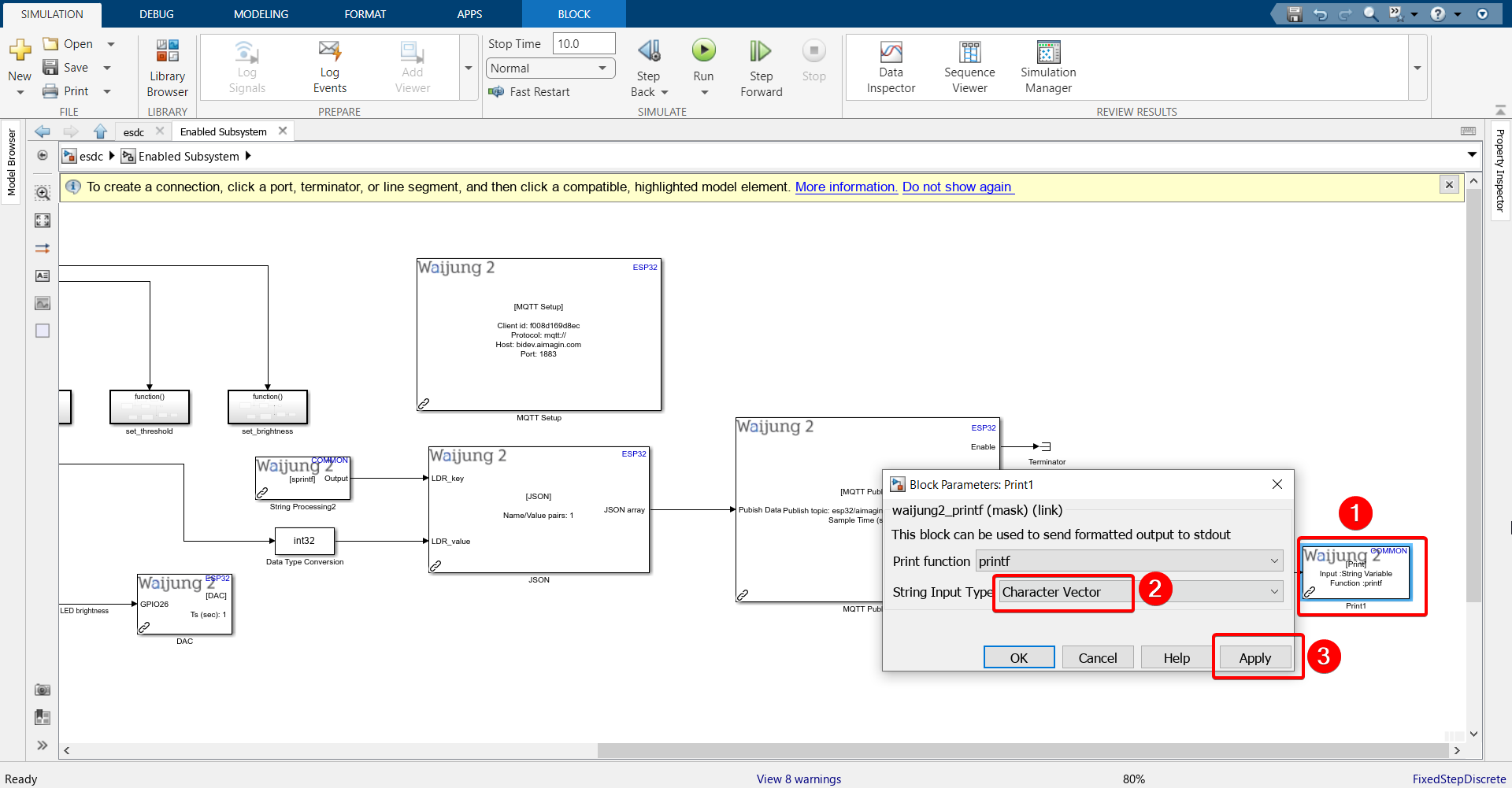
12. Configure Print block.'
13. Connect blocks as shown.
14. Save the file.
15. Go under ‘APPS’ and click ‘Embedded Coder’.
16. Click ‘Build’.
17. Once Build is successful, go to the IP address that you set in the WiFi Setup block, login with your credentials, open your web application.
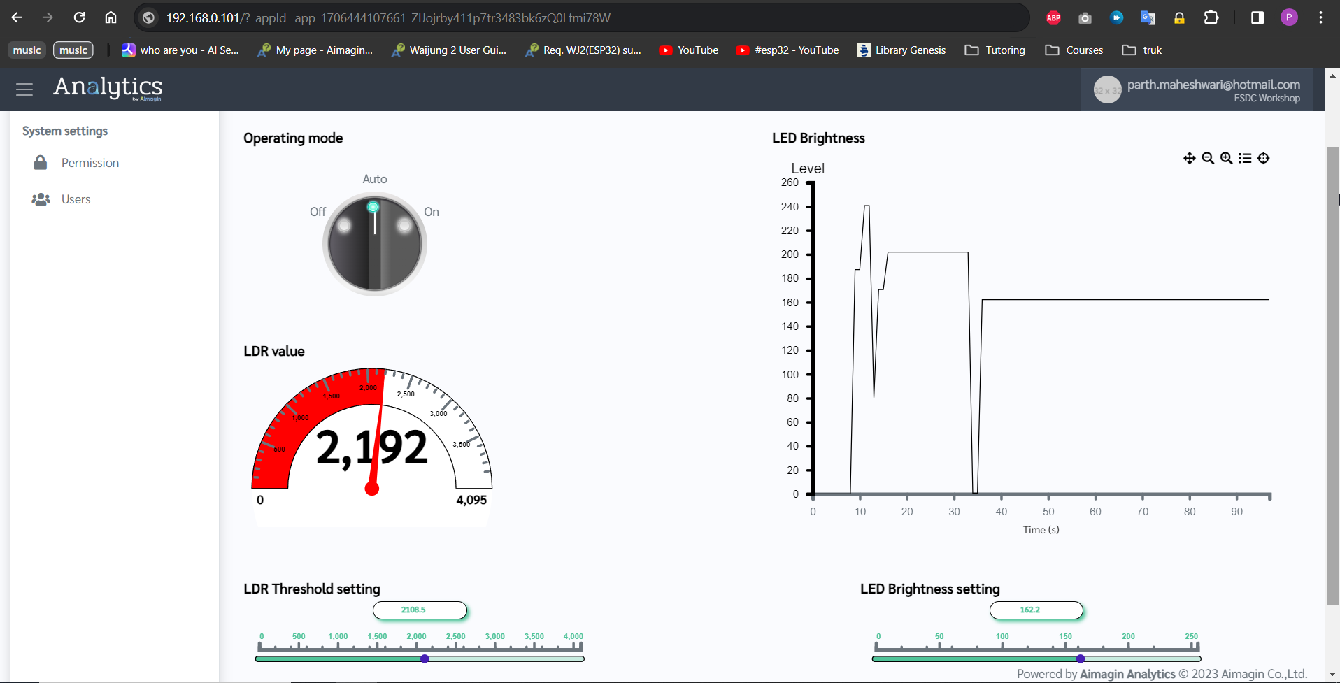
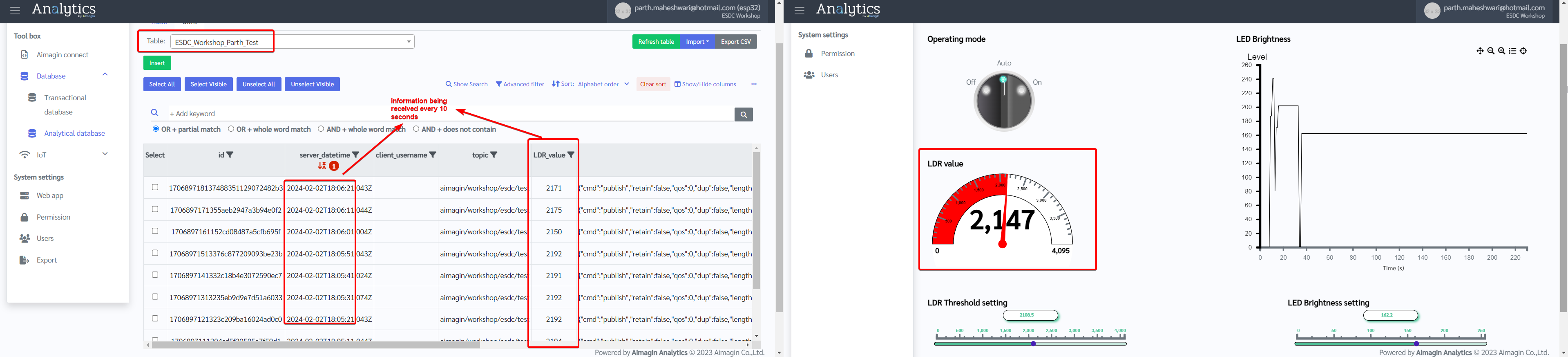
18. Go to https://bidev.aimagin.com/ and open Analytical Database.
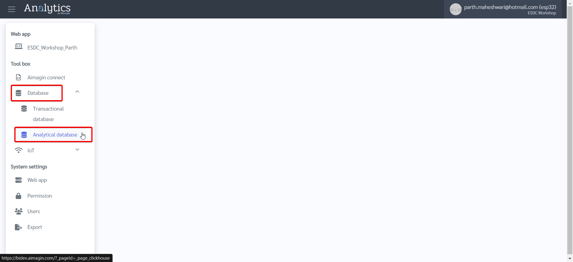
19. Go to Data tab > Select the table you created.
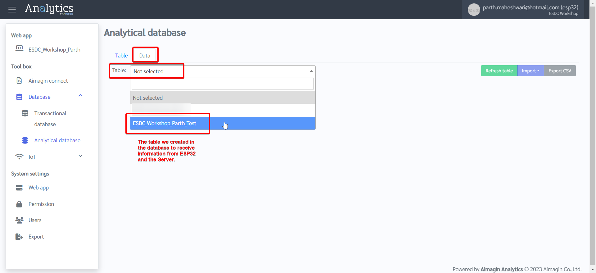
20. Watch information entering database every 10 seconds (as we configured) along with real-time web control and acquisition.
This is the end of Project 11.