Introduction
PIL (Processor-in-the-Loop) testing is a type of software testing used to validate the functionality and behavior of a model (in this case, a Simulink model) in a simulated environment that includes the processor or the microcontroller that the model is designed to run on. PIL testing involves executing the generated code on a processor or a micro-controller that is connected to the simulation environment, allowing you to test the code in a more realistic environment than MIL testing.
Simulink Test is a testing framework provided by MathWorks that enables PIL testing of Simulink models. It allows you to create test cases and test procedures, generate test harnesses, and simulate the model with various inputs and configurations to validate its behavior while executing the generated code on the processor or the micro-controller.
Pros of PIL testing with Simulink Test:
•PIL testing provides a more realistic testing environment than MIL testing, as it involves executing the generated code on the processor or the micro-controller that the model is designed to run on.
•It enables you to test the generated code for correctness and efficiency, which is crucial for the actual deployment of the code on the processor or the micro-controller.
•You can create multiple test cases and configurations to cover a wide range of scenarios and inputs.
•Simulink Test can automatically generate test reports and coverage analysis, which can help you identify potential issues and improve the quality of your Simulink model.
Cons of PIL testing with Simulink Test:
•PIL testing requires a processor or a microcontroller that is connected to the simulation environment, which can be costly and time-consuming to set up.
•It may not catch all the issues that can arise when running the code on the actual hardware, as the simulation environment may not exactly replicate the actual hardware.
•Overall, PIL testing with Simulink Test can be a valuable tool to validate the behavior and functionality of the Simulink model and the generated code for the processor or the micro-controller.
This tutorial demonstrate how to use Waijung2 ESP32 block set to conduct testing with Processor-in-theLoop (PIL).
Prerequisites
•ESP32 development board
•USB cable
•Waijung2 ESP32 blockset installed in MATLAB/Simulink
•Basic knowledge of MATLAB/Simulink
Setting Up Hardware
Required to connect Tx pin of UART1 to Rx pin of UART1, to achieve the state of short-circuit.
Block in Use
•Waijung2 Target Setup block
•Waijung2 SD Setup block
•Waijung2 SD Write block
•Waijung2 SD Read block
•Waijung2 UART Setup block
•Waijung2 UART Tx block
•Waijung2 UART Rx block
•Waijung2 String Processing block
•Simulink blocks
Use case scenarios
1.Automotive applications: PIL is commonly used in automotive applications to test and validate electronic control units (ECUs) and other embedded systems. For example, PIL can be used to test the control algorithms for the engine, transmission, and other vehicle systems.
2.Aerospace applications: PIL is also used in aerospace applications to test and validate avionics systems, such as flight control systems and navigation systems. PIL can be used to test the performance of these systems under various flight conditions and scenarios.
3.Medical devices: PIL can be used to test and validate medical devices, such as implantable devices and monitoring systems. PIL enables users to test the device's functionality and performance in real-time, ensuring that it meets the necessary safety and reliability requirements.
4.Industrial automation: PIL can be used in industrial automation applications to test and validate programmable logic controllers (PLCs) and other control systems. PIL enables users to test the control algorithms in real-time, ensuring that the system operates as expected under various operating conditions.
5.Consumer electronics: PIL can be used to test and validate consumer electronics, such as smartphones, tablets, and wearables. PIL enables users to test the device's functionality and performance on the actual hardware, ensuring that it meets the necessary performance and reliability requirements.
Test Cases
TC001: Comparing Input & Output values
TC002: Testing with different sample time
Expected Output
Input and output signal must be matched after the pulse sent by the signal builder.
Limitation
Setting Up Test Cases
Step 01: Create Test Harness
Right-click on the "Model" block > Select "Test Harness" > Select "Create for 'Model'"

Step 02: Configure Test Harness- Basic Properties
Select Sources and Sinks.

Step 03: Configure Test Harness- Advance Properties
Select Verification Mode: Processor-in-the-Loop (PIL) for PIL testing.

Step 04: Open Test Manager from Test Harness Model
Select "HARNESS" tab and select "Simulink Test Manager" in the "TEST CASES" section

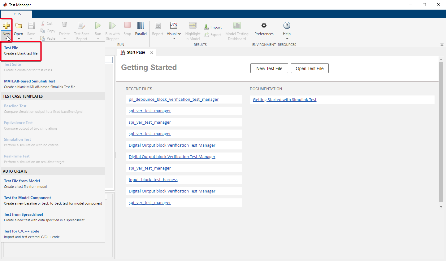
Step 05: Create Test File in the Test Manager

Step 06: SYSTEM UNDER TEST - Select Model
In order to select the model, go to "SYSTEM UNDER TEST" section on the "esp32 PIL validation" and select "Use current model" (second icon).

Step 07: SYSTEM UNDER TEST -
1.Step 06
2.Press refresh button to load the current test harness into the test manager
3.Select the test harness from the drop down list
4.Under the section "Simulation Settings and Release override", select the "Processor-in-the-loop (PIL)" from the drop down list

Step 09: CALLBACKS
There are 3 callback options in the Simulink Test Manager:
1.PRE-LOAD - Runs before the model loads and any model callbacks.
2.POST-LOAD - Runs after the model loads and the model PostLoadFcn callback.
3.CLEANUP - Runs after Simulation and the all model callbacks.
Callbacks can be use to change model/mask parameters, add/remove/comment blocks which is useful while testing different functions using multiple test cases.
In this tutorial, POST-LOAD & CLEANUP callback will be used. Enter the following line of codes into respective callbacks as shown in the below image,

Step 10: INPUTS
•Check the first check box to display the input signal alongside the output signals in results.
•Check the second check box to stop simulation at the end point of the input signal.
In this tutorial signal builder block was used as the Source while creating the Test Harness. In order to use Signal builder block in test harness model check the "Signal Editor scenario" check box and select "Group 1".
In order to edit the selected signal click on the diagonal arrow icon.

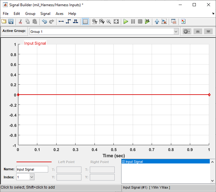
Step 11: INPUTS - Creating Signals using Signal Builder

•Select the signal in the plot.
•Go to Signal > Replace with > Pulse.

•Select "OK".
•Here is the random "Group 1" Signal

•Save the Signal Builder & Test Manager.
Step 12: SIMULATION OUTPUTS
•Select "+ Add" button to add outputs.

•Select output signals of the Test Harness:pil_Harness model & check the check boxes.

•Select "Done" in the Test Manager after selecting the output signals on Test Harness model.

•Above actions will create a "Signal Set 1" with the selected signal as shown in the following image.

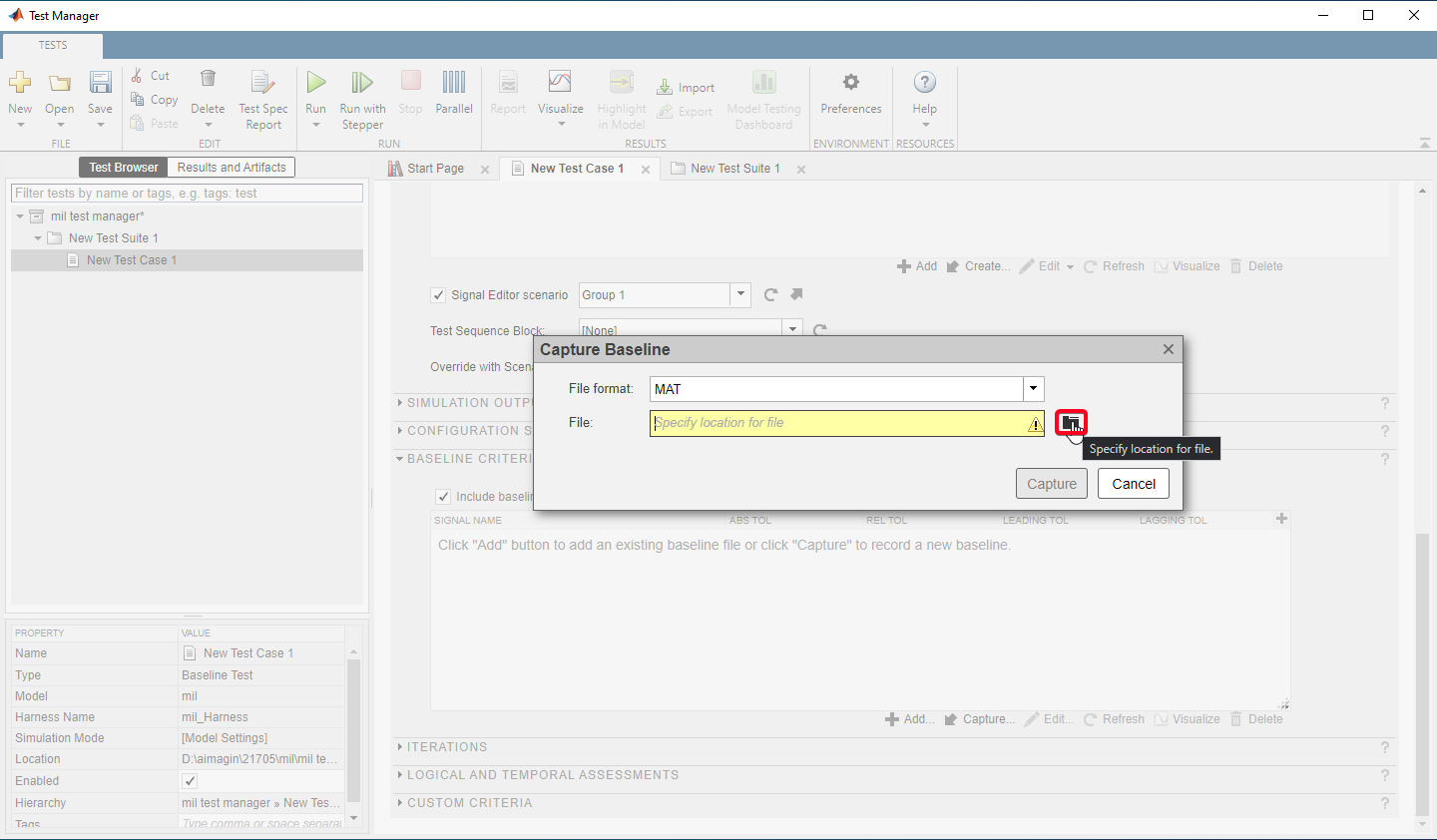
Step 14: BASELINE CRITERIA - Capturing baseline data
•Select Check box for include baseline data in test result.
•In order to capture the baseline data select capture button.

•Select file path to save the baseline data

•Click "Capture" button to capture the baseline data.

•To continue with the simulation, Click "Continue" button.

•Baselines can be visualize using the button call "Visualize" using the Data Inspector.

How to create Test Spec Report
Step 01: Select "Test Spec Report"

Step 02: Insert/Select Title, Author, Includes in Report, File Format, File Name etc.. and Select "Create"

•Generated test spec file: pil_testspec.pdf
How to Run Test Cases
•In order to run, Select the test file/suite/case and click on "Run" button.

•Click on the button "Continue" to continue with the simulation when host-board connection is set to Serial in the waijung2 target setup block.

Other Method
•If the host-board connection is set to TCP/IP in the waijung2 target setup block, before clicking on the button "Continue",
•Connect to the WiFi,

•Once the computer is connected to the WiFi - esp-pil, Click on the button "Continue" to continue with the simulation

Test Results and Generate Test Result Report
Step 01: Test Results can be visualize in the "Results & Artifacts" tab of Test Manager
Step 02: Generate Test Result Report
•Right -Click on the test file/suite/case and Select "Create Report".


•Generated test Result file: pil_result.pdf
Source Files
•PIL Test Files - Test_Files.rar
