Introduction
This tutorial demonstrate how to use Waijung2 ESP32 block set to conduct testing with Model-in-the-Loop (MIL).
MIL (Model-in-the-Loop) testing is a type of software testing used to validate the functionality and behavior of a model (in this case, a Simulink model) in a simulated environment. It involves testing the model itself, without the hardware or the generated code, by connecting the model to a simulated environment that mimics the inputs and outputs of the real-world system.
Simulink Test is a testing framework provided by MathWorks that enables MIL testing of Simulink models. It allows you to create test cases and test procedures, generate test harnesses, and simulate the model with various inputs and configurations to validate its behavior. For more details: Simulink Test:
Documentation: https://www.mathworks.com/help/sltest/ug/unit-testing-with-simulink-test.html
Pros of MIL testing:
•Simulink Test provides a simulation environment that allows you to test the Simulink model without the need for the actual hardware or the generated code.
•It enables early testing and validation of the Simulink model before deploying it on the ESP32 micro controller.
•You can create multiple test cases and configurations to cover a wide range of scenarios and inputs.
•Simulink Test can automatically generate test reports and coverage analysis, which can help you identify potential issues and improve the quality of your Simulink model.
Cons of MIL testing:
•Since MIL testing involves testing the model without the actual hardware, it may not catch all the issues that can arise when running the code on the ESP32 micro controller.
•MIL testing does not cover the testing of the generated code, which is crucial for the actual deployment of the code on the micro controller.
Prerequisites
•Basic knowledge of MATLAB/Simulink
Block in Use
•Simulink Blocks
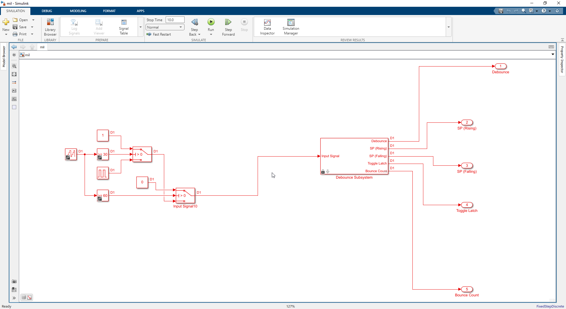
Test Model:mil.slx
Use Case Scenario
How to conduct automated simulation testing using Model-in-Loop (MIL).
Test Cases
TC001: Testing Parameter values
TC002: Testing with different input
Expected Output
Generate test reports.
Setting Up Test Cases
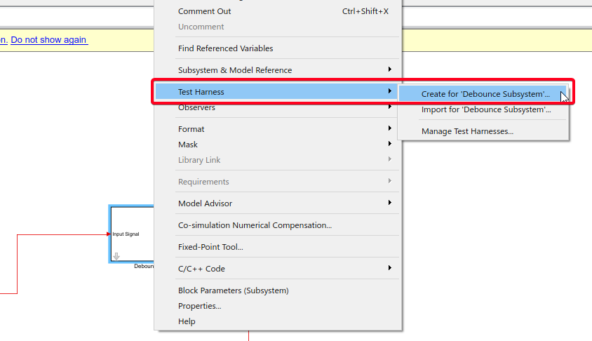
Step 01: Create Test Harness
Right-click on the "Debounce Subsystem" block > Select "Test Harness" > Select "Create for 'Debounce subsystem'"
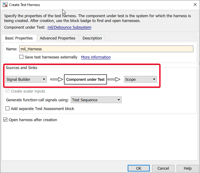
Step 02: Configure Test Harness- Basic Properties
Select Sources and Sinks.
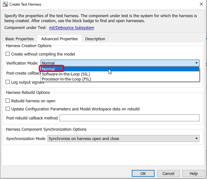
Step 03: Configure Test Harness- Advance Properties
Select Verification Mode: Normal for MIL testing.
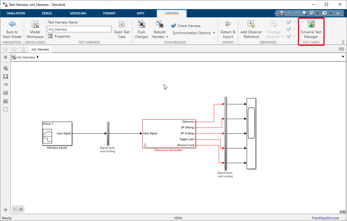
Step 04: Open Test Manager from Test Harness Model
Select "HARNESS" tab and select "Simulink Test Manager" in the "TEST CASES" section
Step 05: Create Test File in the Test Manager
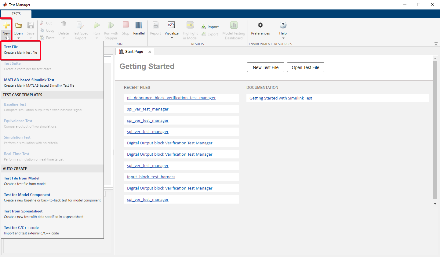
Test Manager File: mil test manager.mldatx
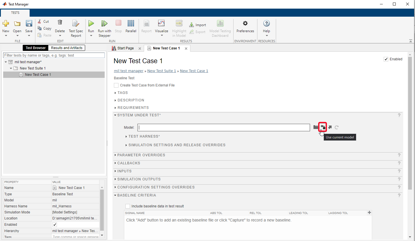
Step 06: SYSTEM UNDER TEST - Select Model
In order to select the model, go to "SYSTEM UNDER TEST" section on the "New Test Case 1" and select "Use current model" (second icon).
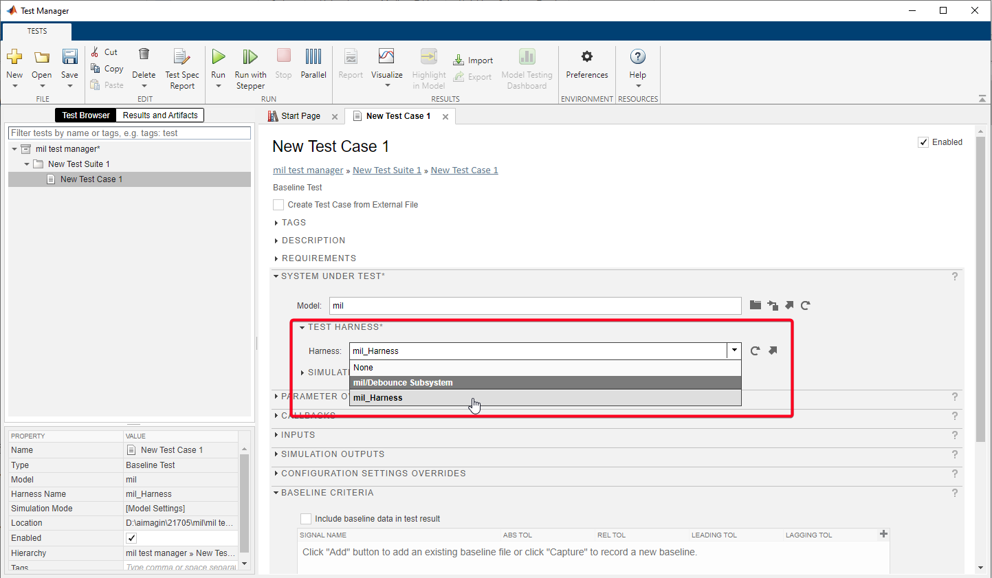
Step 07: SYSTEM UNDER TEST - Select Test Harness
Expand "TEST HARNESS" section and select test harness "mil_Harness"
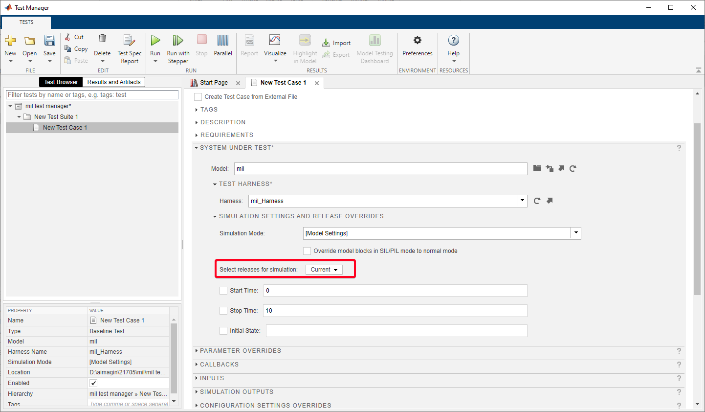
Step 08: SYSTEM UNDER TEST - Simulation Settings and Release override
Select the Matlab version/release to test, in the section "Select releases for simulation:". (Only shows the installed Matlab releases on the computer)
Tick the check boxes to configure specific "Start Time", "End Time" & "Initial State" for current test case.
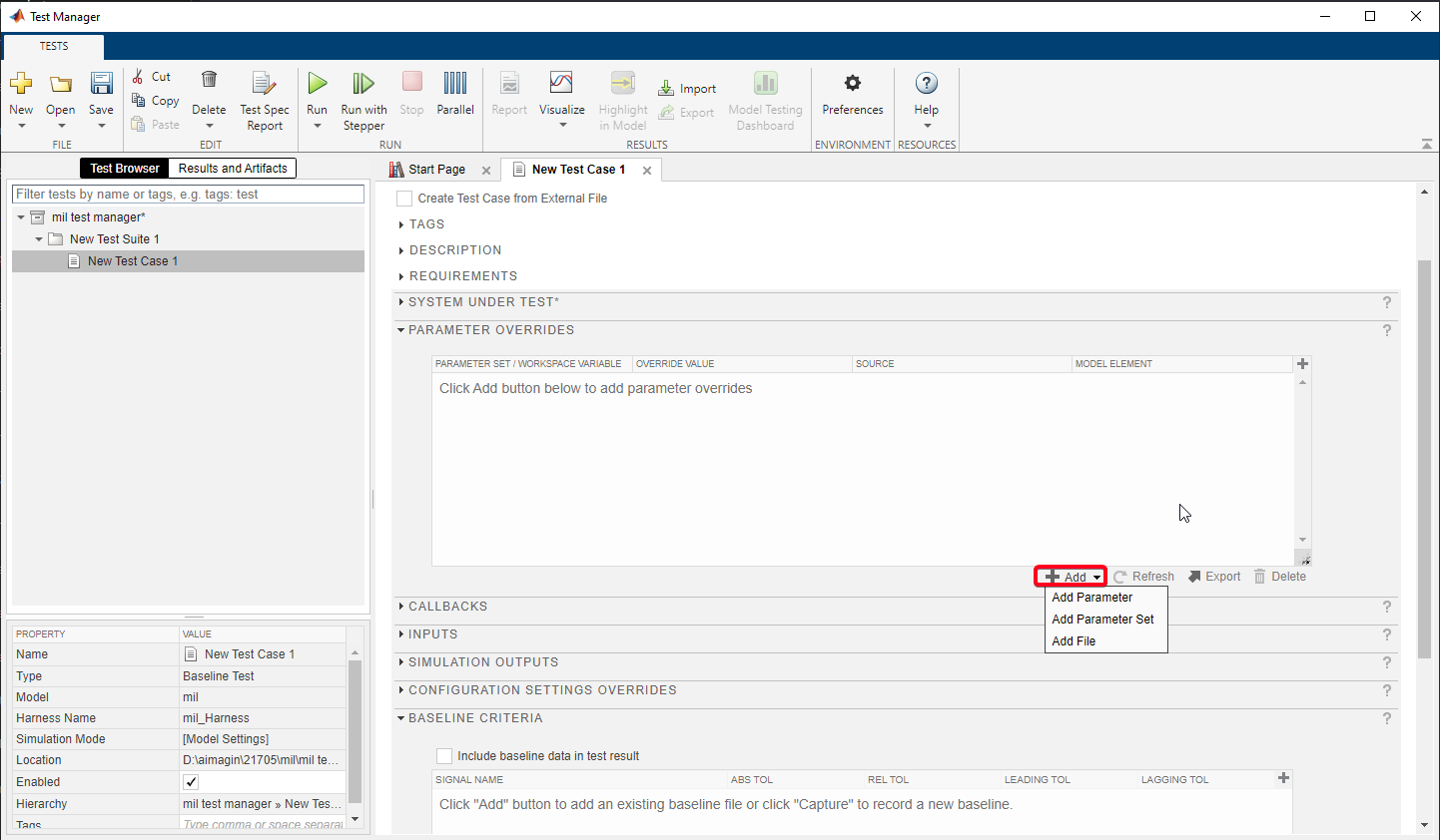
Step 09: PARAMETER OVERRIDES
Select "Add" icon and select "Add Parameters".
Click on refresh icon to display model parameter list.

Select Check boxes of "debouncerise" & "debouncefall" and select "OK"

To facilitate the creation of a test case that encompasses a range of parameter values, Right-click on the "Parameter Set 1" , then copy and paste to create the "Parameter Set 2".
Use "OVERRIDE VALUE" column to change parameter value.

Step 09: CALLBACKS
There are 3 callback options in the Simulink Test Manager:
1.PRE-LOAD - Runs before the model loads and any model callbacks.
2.POST-LOAD - Runs after the model loads and the model PostLoadFcn callback.
3.CLEANUP - Runs after Simulation and the all model callbacks.
Callbacks can be use to change model/mask parameters, add/remove/comment blocks which is useful while testing different functions using multiple test cases.
Note: This(MIL) tutorial does not use callbacks section in the Test manager. Please refer the Processor-in-the-Loop (PIL) Testing tutorial for more information.
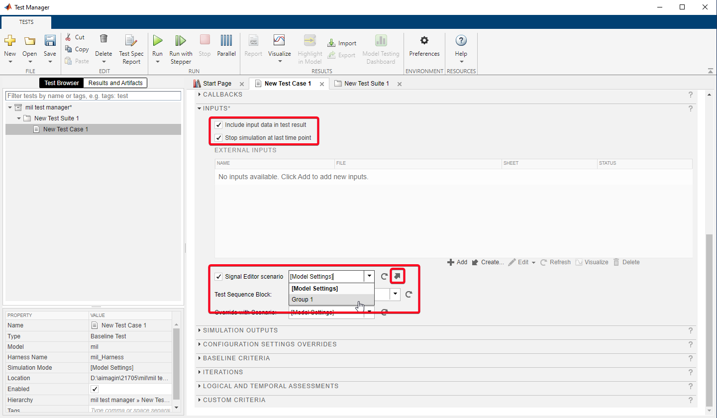
Step 10: INPUTS
•Check the first check box to display the input signal alongside the output signals in results.
•Check the second check box to stop simulation at the end point of the input signal.
In this tutorial signal builder block was used as the Source while creating the Test Harness. In order to use Signal builder block in test harness model check the "Signal Editor scenario" check box and select "Group 1".
In order to edit the selected signal click on the diagonal arrow icon.
Step 11: INPUTS - Creating Signals using Signal Builder
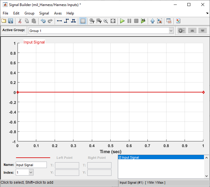
•Select the signal in the plot.
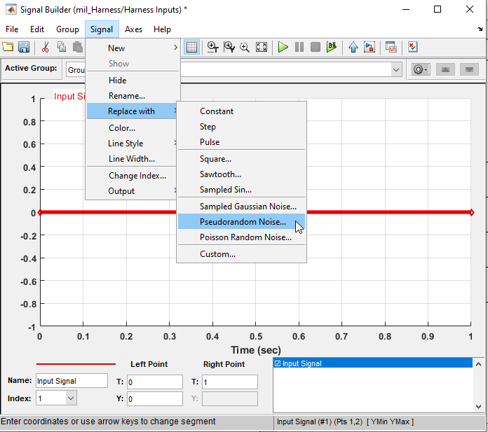
•Go to Signal > Replace with > Pseudorandom Noise.
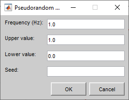
•Select "OK".
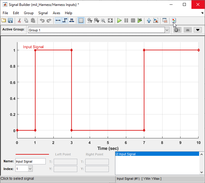
•Here is the random "Group 1" Signal
•To create a new group signal, Select the Gear icon next to the "Active Group" drop down.
•Then Select "copy".
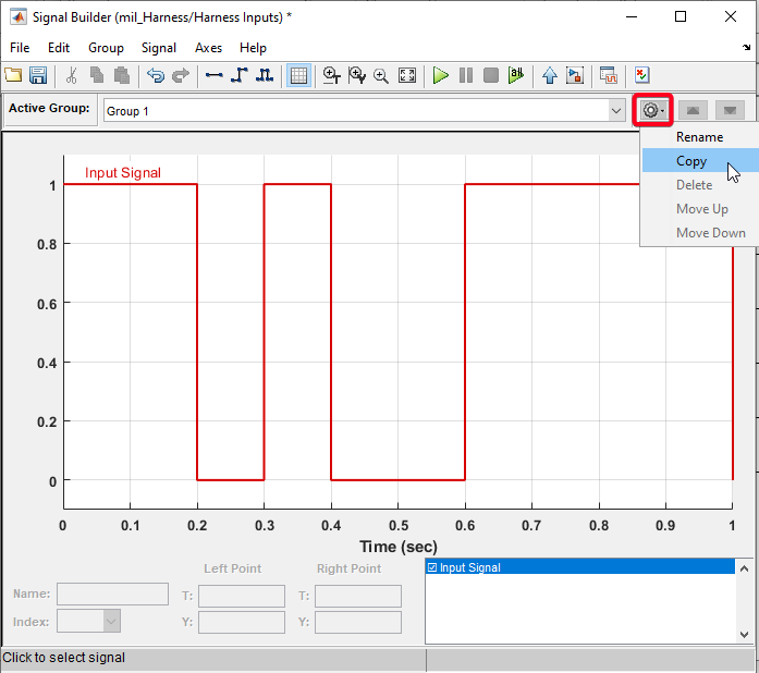
•Signal Builder will display a copy of the signal "Group 1" as "Group 2".
•Select the "Group 2" from the drop down.
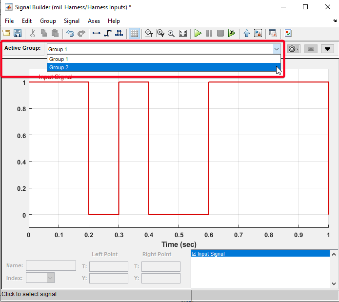
•Select the Signal on the plot & Go to Signal > Replace with > Pseudorandom Noise.
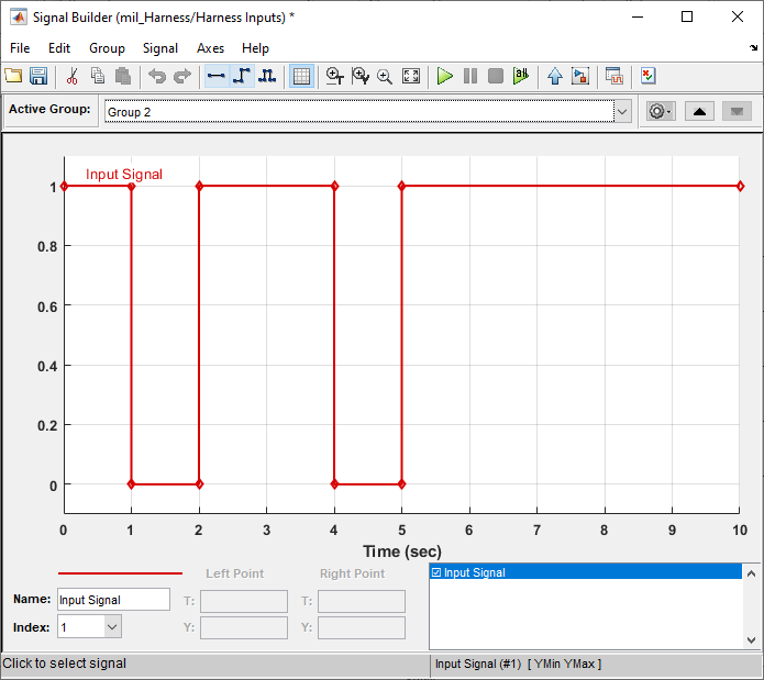
•Save the Signal Builder & Test Manager.
Step 12: SIMULATION OUTPUTS
•Select "+ Add" button to add outputs.

•Select output signals of the Test Harness:mil_Harness model & check the check boxes.
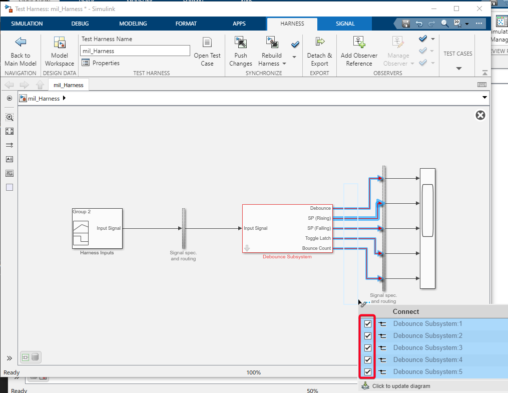
•Select "Done" in the Test Manager after selecting the output signals on Test Harness model.

•Above actions will create a "Signal Set 1" with the selected signal as shown in the following image.

Step 13: ITERATIONS - Auto Generating table iterations
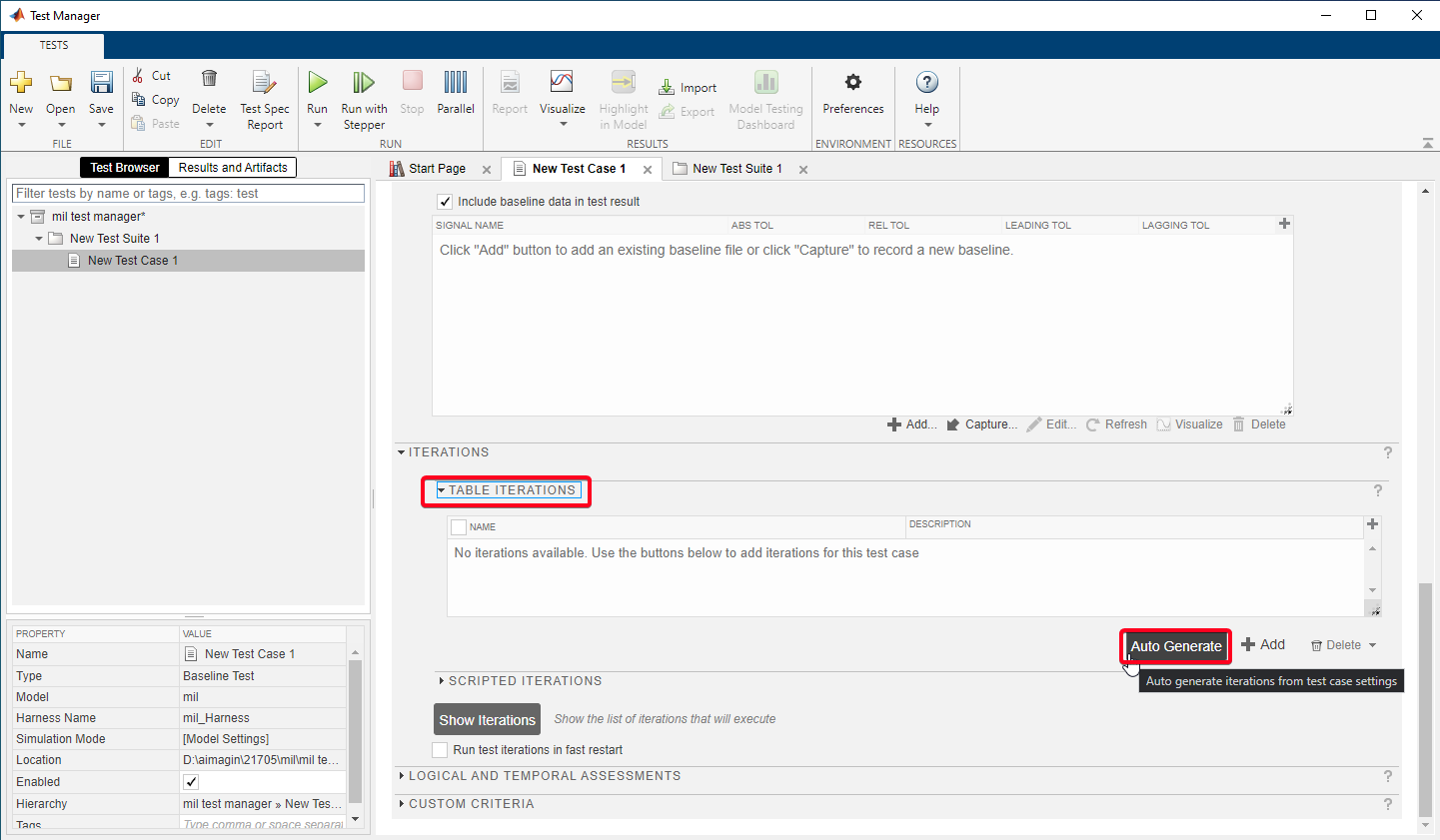
•Expand the "TABLE ITERATIONS" Section.
•Select "Auto Generate" button.
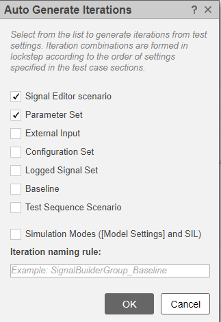
•Select "Signal Editor scenario" & "Parameter Set" check boxes and select "OK".
•In order to add additional iterations Select the "+ Add" button.
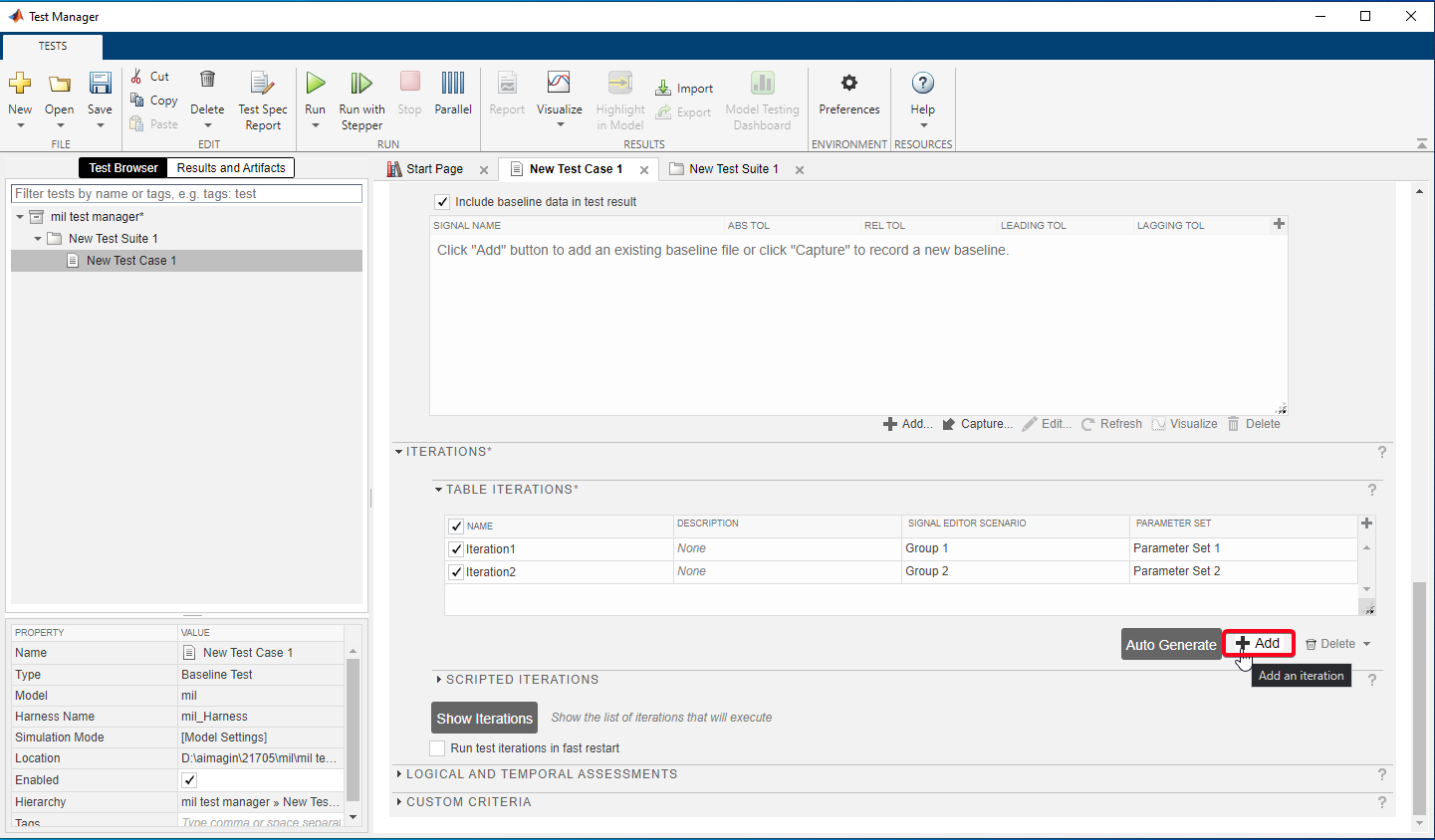
•Change Signal editor scenario and Parameter Set from drop down to create iteration table as follow:

Step 14: BASELINE CRITERIA - Capturing baseline data
•Select Check box for include baseline data in test result.
•In order to capture the baseline data select capture button.
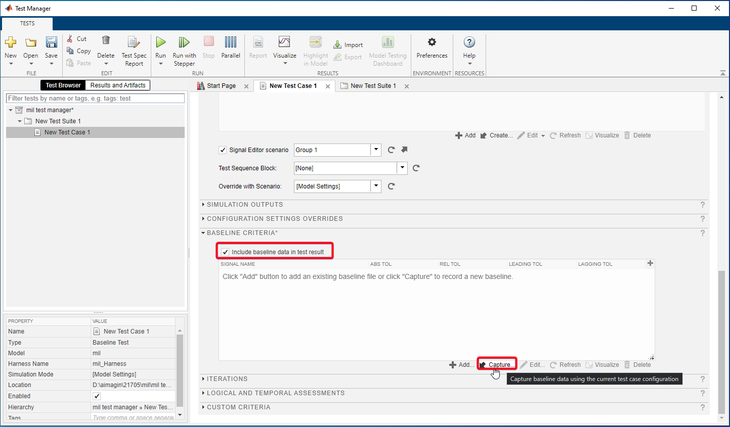
•Select file path to save the baseline data
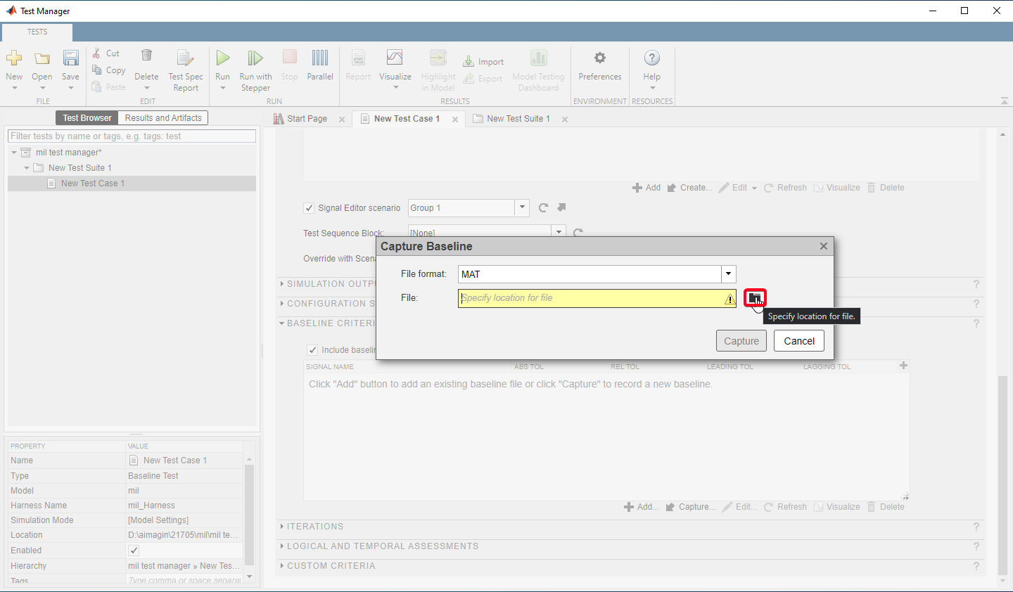
•Check the "Capture Baselines for Iterations" check box and select capture.

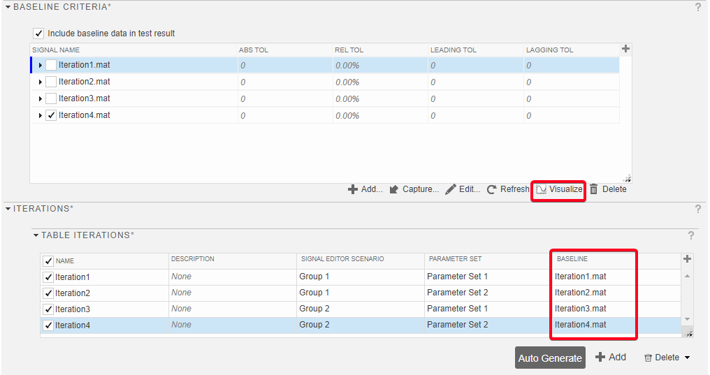
•Baselines can be visualize using the button call "Visualize" using the Data Inspector.
•Completion of capturing baseline will automatically update the corresponding baseline to the iteration in the "TABLE ITERATIONS"
How to create Test Spec Report
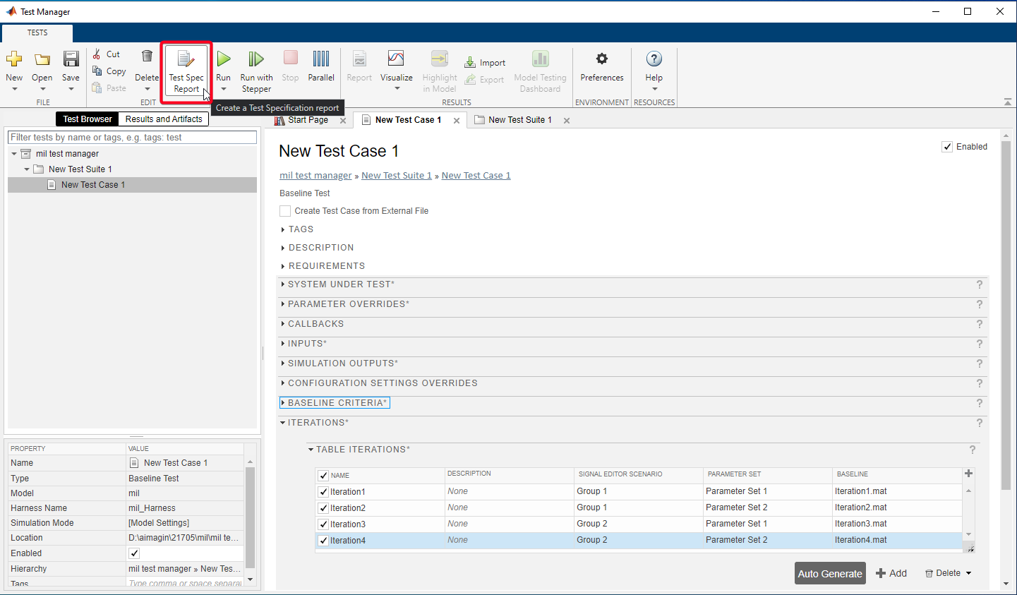
Step 01: Select "Test Spec Report"
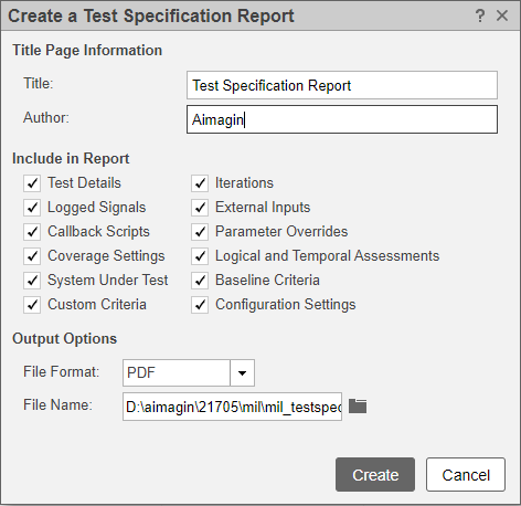
Step 02: Insert/Select Title, Author, Includes in Report, File Format, File Name etc.. and Select "Creat"
•Generated test spec file: mil_testspec.pdf
How to Run Test Cases
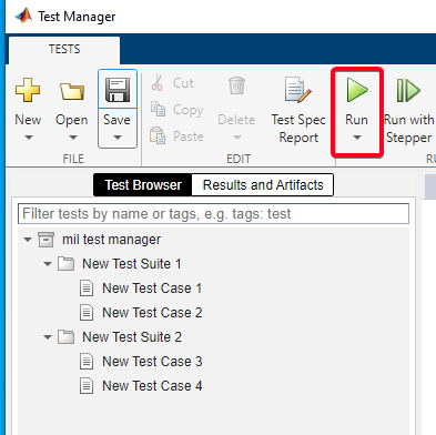
•In order to run, Select the test file/suite/case and click on "Run" button.
Test Results and Generate Test Result Report
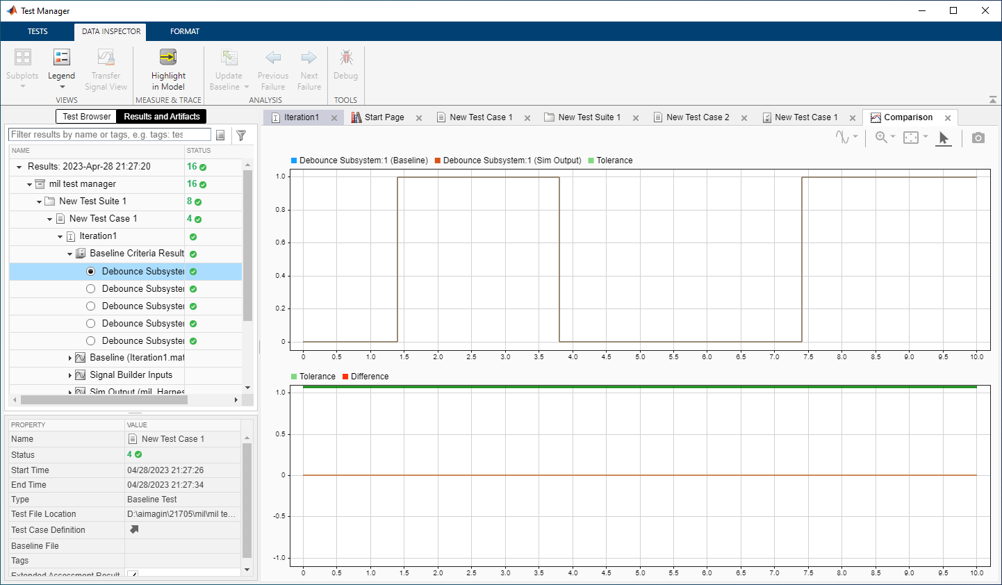
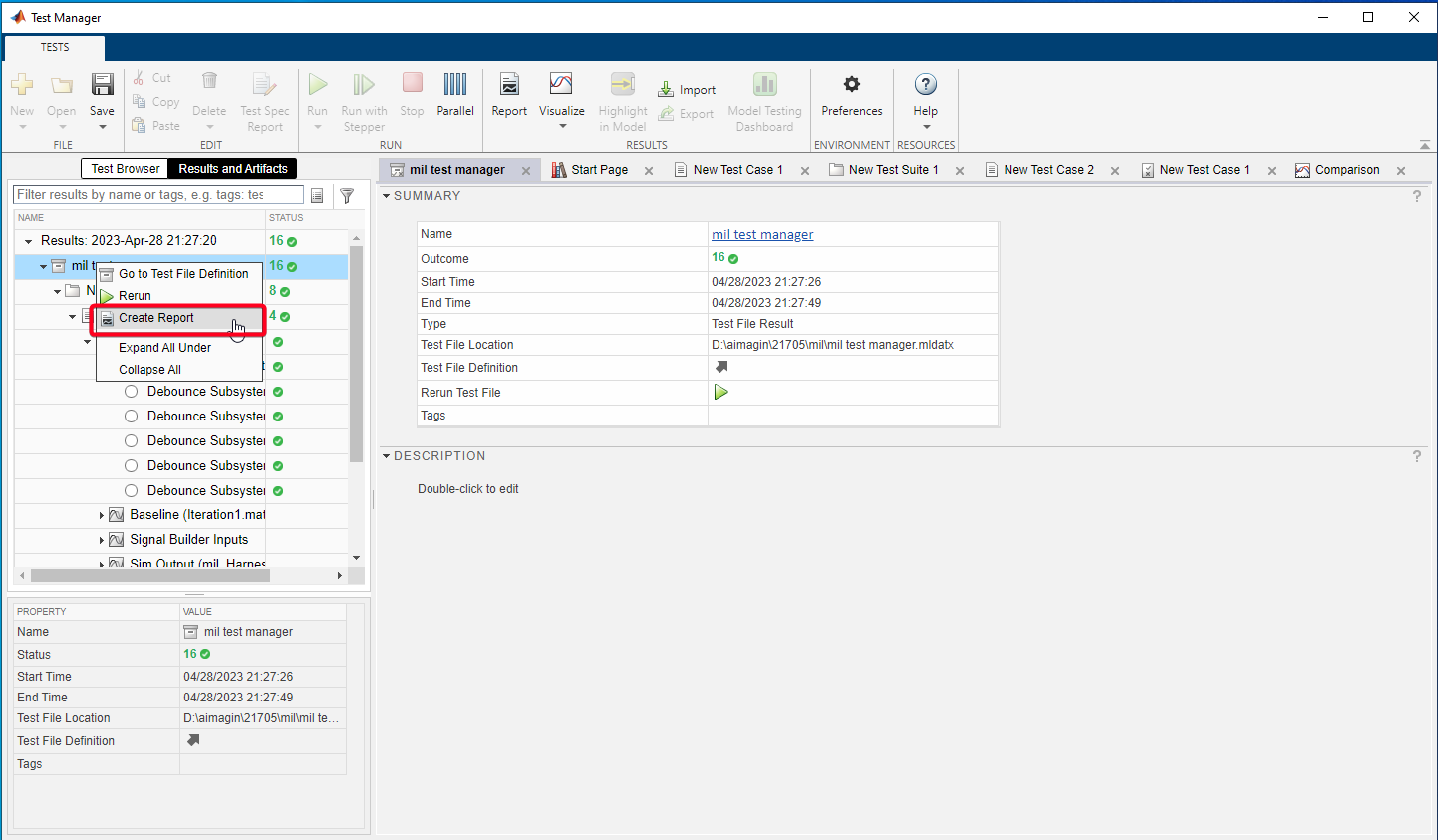
Step 01: Test Results can be visualize in the "Results & Artifacts" tab of Test Manager
Step 02: Generate Test Result Report
•Right -Click on the test file/suite/case and Select "Create Report".
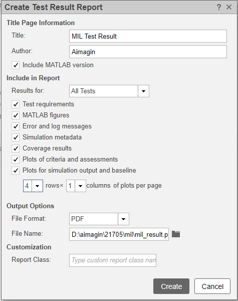
•Generated test Result file:mil_result.pdf
