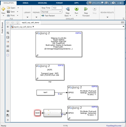
How this block appears in a Simulink model?
What can be configured?
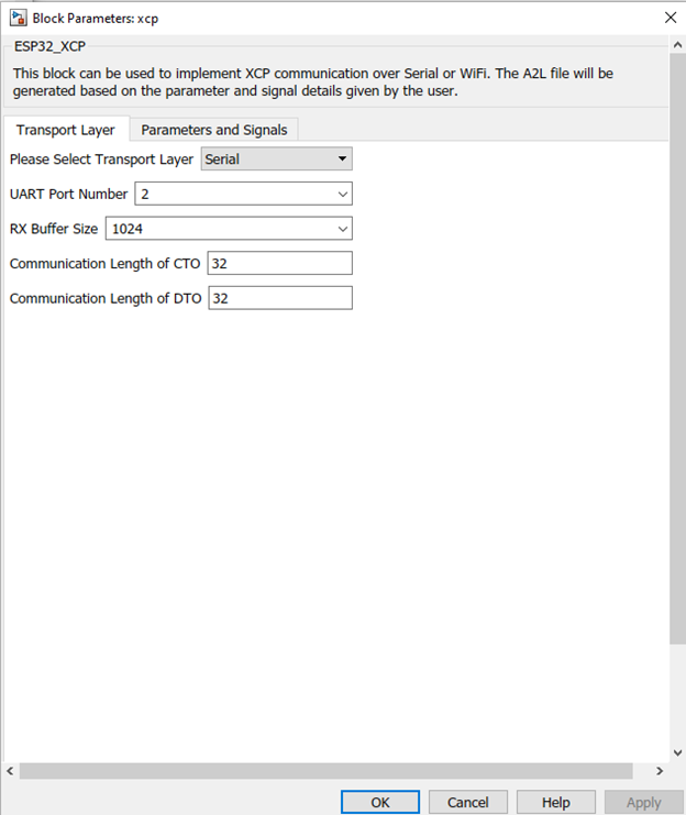
Transport Layer
Configuration Parameter |
Selectable Option/Value |
Description |
Transport Layer |
Serial/WiFi |
For selecting the communication method for the XCP communication between the Master and the Slave. |
UART Port Number |
0 to 4 |
The UART port number selected for the UART_Setup block needs to be entered here. When using the XCP over Serial method the UART_Setup block also need to be included in the Simulink Model. |
RX Buffer Size |
|
The Buffer size selected for Receive (RX) for the UART_Setup block needs to be entered here. |
Communication Length of CTO |
|
Set the communication length of the CTO. Default value is set to 32. Please refer XCP documentation linked under additional information for information about CTO. |
Communication Length of DTO |
Set the communication length of the DTO. Default value is set to 32. Please refer XCP documentation linked under additional information for information about DTO. |
|
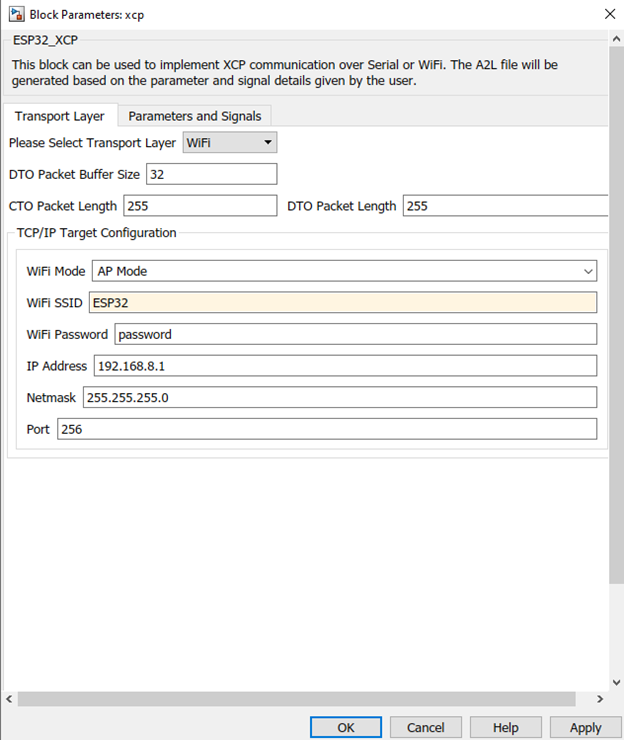
DTO Packet Buffer Size |
|
Set the packet size for the DTO buffer. Default value is set to 32. Please refer XCP documentation linked under additional information for information about DTO. |
CTO Packet Length |
|
Set the packet length of the CTO. Default value is set to 255. Please refer XCP documentation linked under additional information for information about CTO. |
DTO Packet Length |
|
Set the packet length of the DTO. Default value is set to 255. Please refer XCP documentation linked under additional information for information about DTO. |
WiFi mode |
AP Mode/STA Mode |
Select Access Point mode or Station Mode for the WiFi. |
WiFi SSID |
|
Set the SSID for the WiFi connection |
WiFi Password |
|
Set the password for the WiFi connection |
IP Address |
|
Set the IP address for the WiFi |
Gateway Address |
|
Set the Gateway address for the WiFi |
Netmask |
|
Set the Netmask for the WiFi |
Port |
|
Set the port number |
DNS IP |
|
Set the DNS IP |
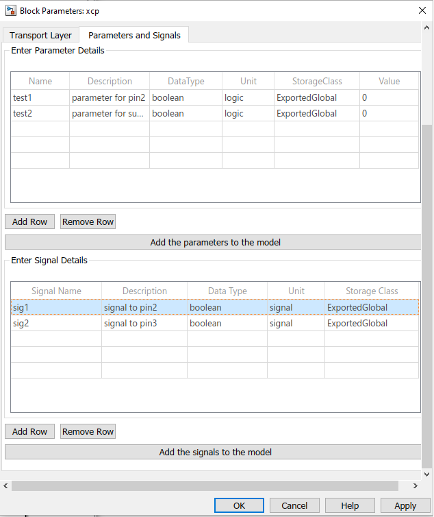
Parameters and Signals
Configuration Parameter |
Selectable Option/Value |
Description |
Name |
|
Enter the name of the parameter/signal |
Description |
|
Enter the description of the parameter/signal to be included in the A2L file. |
Data Type |
boolean, single, double, int8, uint8, int16, uint16, int32, uint32, int64, uint64 |
Select the data type of the parameter/signal |
Unit |
|
Enter the unit of the parameter/signal. This can be simulink based unit or any unit. Ex. Celsius/Fahrenheit |
Storage Class |
ExportedGlobal, Volatile, ConstVolatile |
Select the storage class of the parameter/signal. Storage classes volatile and constant volatile is only available for parameters. |
Value |
|
Enter the value of the parameter. |
Add Row |
|
Add additional rows into the parameter and signal tables. |
Remove Row |
|
Remove unnecessary rows from the parameter and signal tables. |
Add the parameters to the model |
|
Press this button to create Simulink.Parameter objects based on the information on the preceding table. |
Add the signals to the model |
|
Press this button to create Simulink.Signal objects based on the information on the preceding table. |
Note : Please note additional steps are required to add the signals and parameters to the simulink model other than entering the details in the mask shown above. Please see the demo below to see the additional steps required.
Demo 1: Serial
Demo file : esp32_xcp_serial_demo.slx

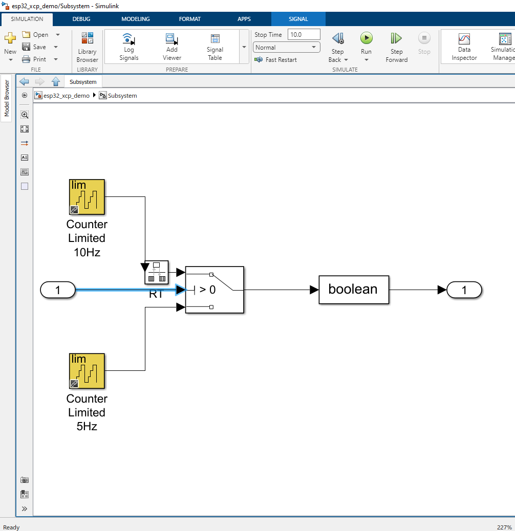
Inside the subsystem.
Description
In this demo the basic functionality of the XCP block will be demonstrated using Digital Output block with the open source HANtune software acting as the master and the ESP32 acting as the slave for the XCP communication over Serial.
Hardware/Software Setup
1. 1 x USB to TTL/UART serial converter
2. 2 x LED with appropriate resistors
3. HANtune build 68 (https://openmbd.com/wiki/Downloads/HANtune)
Download the HANtune open source software developed by HAN University in the above link. HANtune acts as the XCP master to the generated XCP code.
Step by step instructions to get the demo working.
1.Open the esp32_xcp_serial_demo.slx in Simulink. Connect the ESP32 with the USB connector to the PC and select the correct com port for the ESP32 in the Target Setup block.
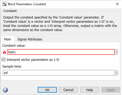
2.On the model double click on the constant blocks to open the mask. In the constant value edit box, enter a chosen name press apply and close the mask. Ignore the warning related to undefined variable which will be sorted by the XCP block on step 5. For this demo it has already been named as “test1” and “test2”.
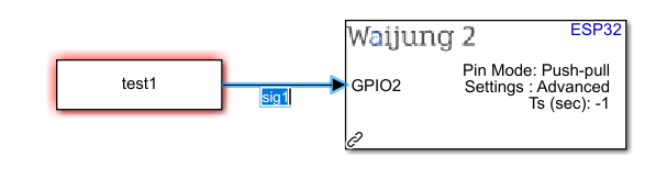
3.Name the signals that needs to be observed by the Master. In this demo we will observe the two signals connected to the two Digital Output blocks. Double click the signal to name it. The signal to GPIO2 should be named to “sig1” and the signal to GPIO3 should be named to “sig2”.
4.Open the XCP block, move to the Parameters and Signals tab.
5.Create the parameters “test 1” and “test2” and include the relevant data types and other information as shown in the image above. If different names were chosen for the parameters make sure to change the parameter names here accordingly. After it is complete press the “add parameters to the model” button to create the Simulink.Parameter objects that will be linked to the model and the A2L file.
6.Enter details for signals “sig1” and “sig2” and enter the relevant information as shown in the image above. Make sure the signal names given in step 3 is given here. Press the “add signals to the model” button to create the Simulink.Signal objects that will be linked to the model and the A2L file. The A2L file facilitates the communication between the XCP master and slave.
7.Open the UART Setup block mask and set the parameters as required. The default parameters used for this demo are as shown below. Please note that the baud rate has to be compatible with the baud rate selected for communication of HANtune software in step 10.
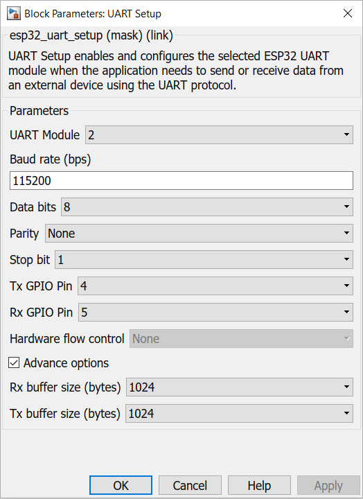
8.Open the XCP block mask and select the transport layer as Serial with the selected port number of step 7. At default it will be set to 115200. For this demo leave the dynamic configuration parameters at their default values.
9.Build and upload the program to the ESP32.
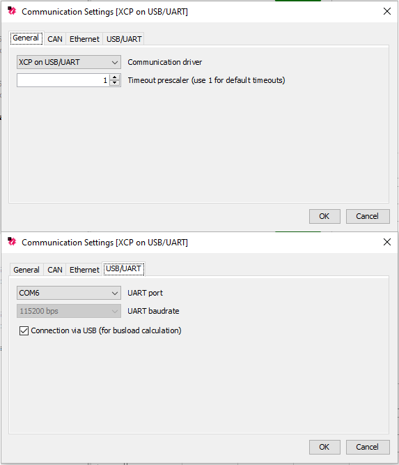
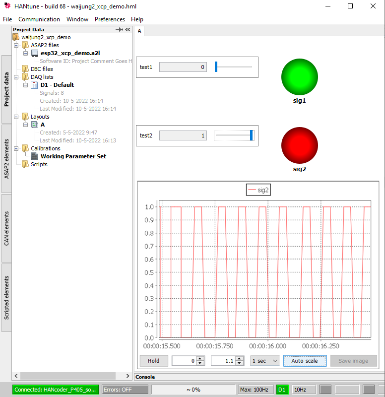
10.Open the HANtune software. Open the waijun2_xcp_demo.hml file included inside the xcp_demo folder. Select communication>communication settings to open up the communication settings tab shown below. Under the general tab select XCP on USB/UART as the communication driver. Under the USB/UART tab select the correct comport for the UART to USB converter connected to the PC. Select the baud rate as 115200. (make sure the baud rate set on the UART Setup block is the same as the baud rate selected here.)
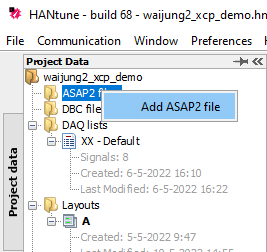
11.Make sure to load the generated A2L file by Right-Clicking the ASAP2 files folder and load the generated esp32_xcp_demo.a2l file. The A2l file can be found in 'esp32_xcp_ demo_esp32’ folder created in the location of the model file.
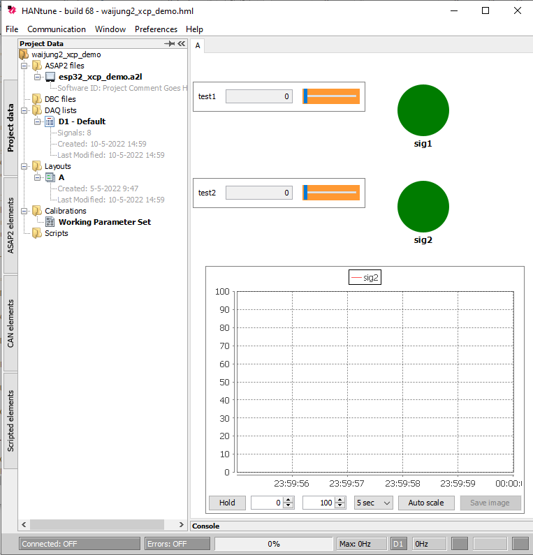
12.After the A2L file has been selected, double click on the name of the A2L file ‘esp32_xcp_ demo.a2l' to load it into the current project. The parameters and signal available from the loaded a2l file can be seen by going to the ASAP2 elements tab on the left side of the HANtune software. Please note a layout needs to be loaded into the project to add these parameters and signals to the interface area. For this demo a layout has already been created and loaded into the project. Any of the parameters and signals on the ASAP2 elements list can be dragged and dropped into the layout to be observed. For this demo “test1”, “test2”, “sig1” and “sig2” parameters and signals will be observed from the interface and should be already loaded in.
13.After the HANtune has also been correctly configured. Go to Communication and Select Connect (or press F5) to connect the master and the slave.Please increase the DAQ frequency from master side using option shown below (Press the green D1 button while communication is underway to get the window shown below) to get a better resolution of the received signals. It is advised to change this value to 100Hz at runtime.
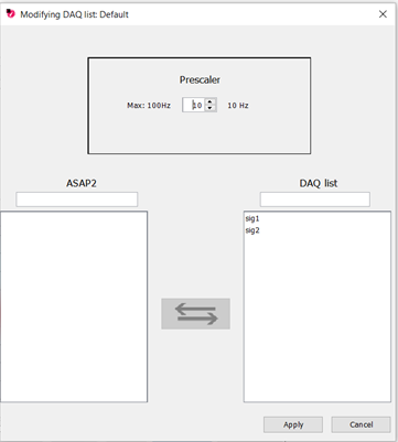
What should be happening?
After the communication has been setup correctly with the slave (ESP32), turning on/off the “test 1” parameter will turn on and off the GPIO pin 2. “Sig2” signal will also change based on the state of the “test1” parameter. This can also be seen if an LED is connected to the GPIO pin 2. If an ESP32 DEVKit board is used, the onboard LED will be turned on and off.
Turning on/off the “test 2” parameter will change the output of to the GPIO pin 3 and “sig2” signal between 10Hz and 5Hz. This can be seen by the graph in the project interface and also by connecting an LED to the GPIO pin 3.
Demo 2: WiFi
Demo file : esp32_xcp_wifi_demo.slx
Description
In this demo the basic functionality of the XCP block will be demonstrated using Digital Output block with the open source HANtune software acting as the master and the ESP32 acting as the slave for the XCP communication over Wifi.It is also possible to use HANtune open source software for this same purpose. Please refer documentation on demo for xcp over serial (Demo 1) to get a better idea how to use HANtune for this purpose.
Hardware/Software Setup
1. 2 x LED with appropriate resistors
2. HANtune build 68 (https://openmbd.com/wiki/Downloads/HANtune) or ASAP2Demo (https://jnachbaur.de/ASAP2Demo/Downloads.html)
Download the HANtune open source software developed by HAN University in the above link. HANtune acts as the XCP master to the generated XCP code.
Download the ASAP2Demo software developed by JNachbaur in the above link. ASAP2Demo can act as the XCP master to the generated XCP code.
Step by step instructions to get the demo working.
1.Open the esp32_xcp_serial_demo.slx in Simulink. Connect the ESP32 with the USB connector to the PC and select the correct com port for the ESP32 in the Target Setup block.
2.Please follow steps 2-6 from demo 1 to set up parameters and signals in the model and prep the model for A2L file generation which will be done during the build process.
3.Open the XCP block and move to the transport layer tab. Select the wifi mode. For this demo please select the AP mode. ASAP2Demo software chosen as the master for this demo does not support communication over STA mode. HANtune software chosen as the master for demo 1 supports both AP and STA modes.
Please set up the settings for AP mode Wifi connection on the XCP block as preferred.
If using HANtune as the master instead of ASAP2Demo, please make note of the IP address and port number which needs to be setup in HANtune before commencement of communication.
4.Build and upload the program to the ESP32.
5.If you are using HANtune as the Master software please follow below steps 6 to 9. Otherwise if you are using ASAP2Demo as the master follow steps 10 to 12.
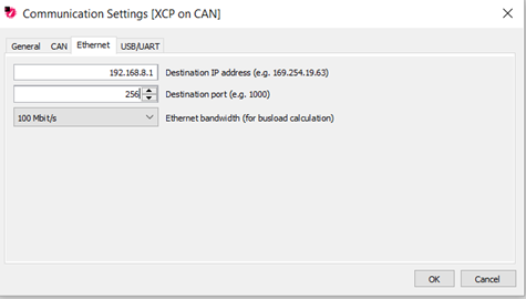
6.Open the HANtune software. Open the waijun2_xcp_demo.hml file included inside the xcp_demo folder. Select communication>communication settings to open up the communication settings tab shown below. Under the general tab select XCP on Ethernet as the communication driver. Under the Ethernet tab enter the correct IP address and port number from step 3.
7.Make sure to load the A2L file generated during the build process by Right-Clicking the ASAP2 files folder and load the generated esp32_xcp_demo.a2l file. The A2l file can be found in 'esp32_xcp_ demo_esp32’ folder created in the location of the model file with the name ‘modelname.a2l’.
8.After the A2L file has been selected, double click on the name of the A2L file ‘esp32_xcp_ demo.a2l' to load it into the current project. The parameters and signal available from the loaded a2l file can be seen by going to the ASAP2 elements tab on the left side of the HANtune software. Please note a layout needs to be loaded into the project to add these parameters and signals to the interface area. For this demo a layout has already been created and loaded into the project. Any of the parameters and signals on the ASAP2 elements list can be dragged and dropped into the layout to be observed. For this demo “test1”, “test2”, “sig1” and “sig2” parameters and signals will be observed from the interface and should be already loaded in.
9.After the HANtune has also been correctly configured. First connect your PC to the WiFi connection created by the ESP32 if using AP mode. If using STA mode instead make sure the PC is connected to the same WiFi connection ESP32 is connected. Go to Communication and select Connect (or press F5) to connect the master and the slave. Please increase the DAQ frequency from master side using option shown below to get a better resolution of the received signals. It is advised to change this value to 100Hz at runtime.
10.If you are using ASAP2Demo as the master, after the build is complete open the ASAP2Demo software and open the generated a2l file which can be found at 'esp32_xcp_ demo_esp32’ folder created in the location of the model file with the name ‘modelname.a2l’.
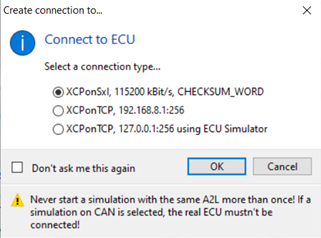
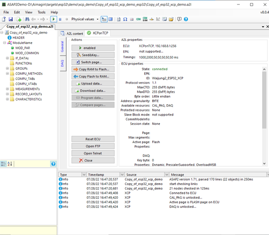
11.When the a2l file is loaded into ASAP2Demo software there will be a prompt to select the communication mode. Please select XCP_ON_TCP option with the IP address and port address as set by step 3. Then connect the PC to the Access Point for Wifi connected by the ESP32. If the connection is successful, you can see the connected status as shown below.
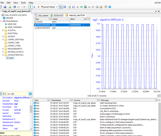
12.To start the data acquisition when using ASAP2Demo, please navigate to the file .bin file which can be found at 'esp32_xcp_ demo_esp32_build_system/build’ folder created in the location of the model file with the name ‘waijung2_esp32.bin’ using any file accessing app or File Explorer.Once navigated to the location, drag and drop the ‘waijung2_esp32.bin’ to the ASAP2Demo software. This should start the DAQ communication and the variables will be available for observation and editing as shown below.
Known issues and limitations
The largest stable frequency that can be observed without abnormal results is around 10Hz and 15Hz for Serial and WiFi respectively.
Generation of the A2L file is done through a matlab function implemented by Aimagin. This is a somewhat simpler a2l generation code which will be applicable in general situations. If the users desire more options to generate the A2L file, Users with Matlab 2021a and later can use the coder.asap2.export method to generate the A2L file through matlab instead after build is completed. If the user is using incompatible matlab versions, they can use A2lPrep (https://openmbd.com/wiki/A2lPrep) to generate the A2L file.
Depending on the user’s PC performance, establishing connection might end in error. If that happens please close all other applications except HANtune and try the connection again.
Additional Information
Refer the following link for additional information on the XCP protocol https://www.asam.net/standards/detail/mcd-1-xcp/wiki/