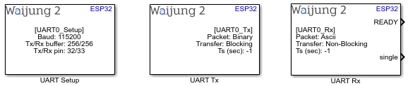
How do these blocks appear in a Simulink model?
What can be configured?
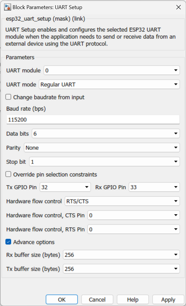
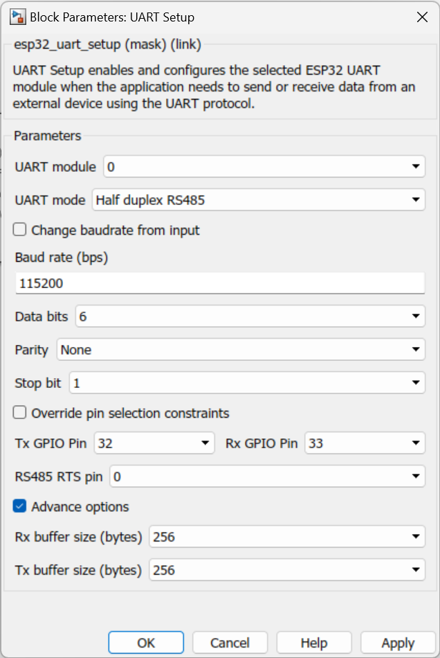
UART Setup
UART Mode - Regular UART
UART Mode - Half duplex RS485
Configuration Parameter |
Selectable Option/Value |
Description |
UART module |
0--1--2 |
Select UART module. |
UART Mode |
Regular UART -- Half duplex RS485 |
Select UART mode |
Change baud rate from input |
Check--Uncheck |
Able to get the baud rate from the input port |
Baud rate (bps) |
Communication speed configuration value, Example: 9600, 115200, or 1000000 |
Select baud rate. |
Data bits |
5--6--7--8 |
Data bit selection |
Parity |
None--Odd--Even |
Parity bit selection |
Stop bit |
1--1.5--2 |
Stop bit selection |
Override pin selection constraints |
Check--Uncheck |
|
TX GPIO Pin |
Not used--0 to 33 |
Pin connect (remap) configuration for transmit pin (Tx). Or select "Not used " to disable Tx for the selected module. |
RX GPIO Pin |
Not used--0 to 39 |
Pin connect (remap) configuration for transmit pin (Rx). Or select "Not used " to disable Rx for the selected module. |
Hardware flow control |
RTS/CTS |
RS 232 and RS485 flow controlling |
Hardware flow control, CTS pin |
0 -- 39 |
CTS pin selection |
Hardware flow control, RTS pin |
0 -- 39 |
RTS pin selection |
RS485 RTS Pin |
0 -- 39 |
RS485 RTS pin selection |
Advanced options |
Check--Uncheck |
This option is to enable advance configuration mode, include memory buffer size. |
Rx buffer size (bytes) |
0--256--512--1024--2048 |
Select buffer size for receiving (Rx) buffer, the size must be in a number of 2^N and higher than packet length. For example, to receive an Rx packet with a length of 90 bytes, the Rx buffer should be configured to 128 or higher. |
Tx buffer size (bytes) |
0--256--512--1024--2048 |
Similar to Rx buffer, the size must be in a number of 2^N and higher than transmit packet length. |
UART Tx
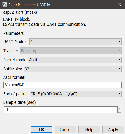
•Packet mode – ASCII
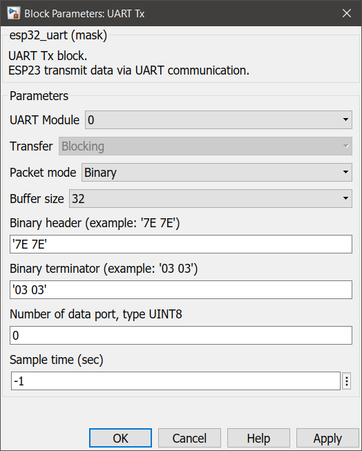
•Packet mode – Binary
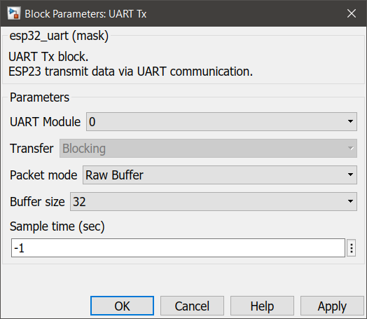
•Packet mode – Raw buffer
Configuration Parameter |
Selectable Option/Value |
Description |
UART module |
0--1--2 |
Select UART module to transmit the Tx data from |
Packet mode |
Ascii--Binary--Raw buffer |
Binary : This packet mode will transmit the packets that contain binary data, by specifying the Header, Data format, and Terminator of a packet to transmit. The block will not transmit the packet which contains an invalid Header or Terminator. Ascii : This packet mode will transmit the packets that contain ASCII data (string), by specifying the sscanf format. The block will create the input port corresponding to the sscanf % format. For example: for the packet format "Value=%d", the input port of the block will be uint32. Raw buffer : This packet mode is transmitting the raw string data. |
Buffer size |
32--64--128--256--512--1024 |
Specify the expected size of the buffer. |
ASCII format |
|
Scanf format specifier, start with %. Below is supported by the block. %u, %i, %d, %o, %x: sscanf input will be the type of uint32 %e, %g, %f : sscanf input will be the type of single %s: sscanf input will be the type of string. |
End of packet |
CR--LF--CRLF |
Terminator in ASCII mode is used to detect the end of the packet. The block will transmit ASCII with the terminator. |
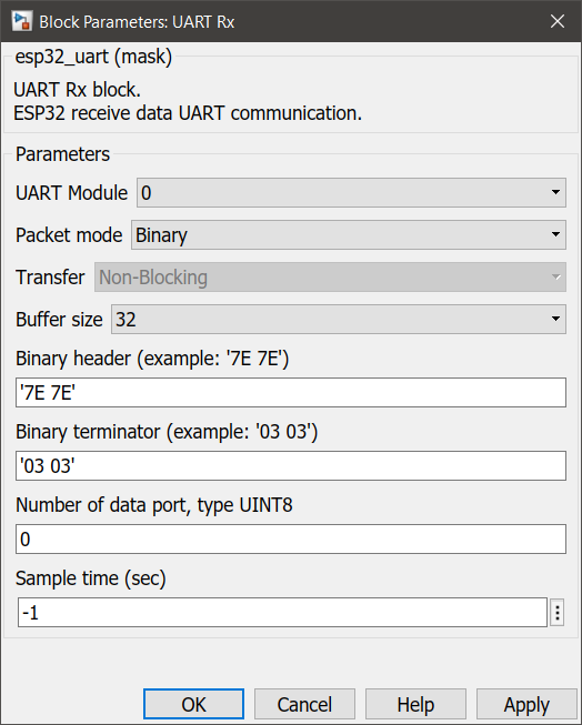
Binary header |
Specify the Header pattern of the packet to transmit |
This header is used for packet synchronization. |
Binary terminator |
Specify the terminator pattern of the packet to transmit |
This terminator is used for packet validation. |
Number of data port, Type UINT8 |
Number of data type uint8 in packet |
1 data port of this data type contains 1byte in the packet. |
Sample time (sec) |
-1 (inherited) or specify |
Specify the sample time. |
UART Rx
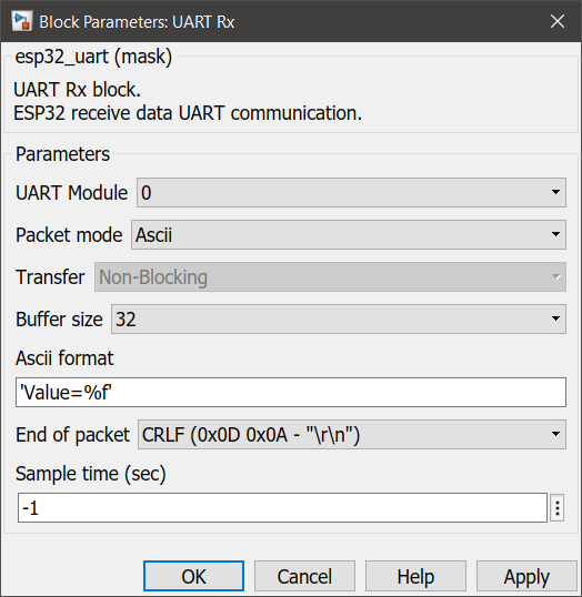
•Packet mode – ASCII
•Packet mode – Binary
•Packet mode – Read Line
•Packet mode – Raw Buffer
Configuration Parameter |
Selectable Option/Value |
Description |
UART module |
0--1--2 |
Select UART module to receive the Rx data from |
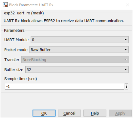
Packet mode |
Ascii--Binary--Read Line--Raw Buffer |
Binary : This packet mode will accept the packets that contain binary data, by specifying the Header, Data format and Terminator of a packet to receive. The block will not accept the packet which contains invalid Header or Terminator. Ascii : This packet mode will accept the packets that contain ASCII data (string), by specifying the sscanf format. The block will create the output port corresponding to the sscanf % format. For example: for the packet format "Value=%d", the output port of the block will be uint32. If packet "Value=100" is received, the block will return 100 to the output port of the block. Read Line : This packet mode is receiving the raw string data and stores it into the string buffer directly without processing the packet. Raw Buffer : This packet mode is receiving the raw data from the uart and output received data without any processing. |
Buffer size |
32--64--128--256--512--1024 |
Specify the expected size of the buffer. |
ASCII format |
|
Scanf format specifier, start with %. Below is supported by the block. %u, %i, %d, %o, %x: sscanf output will be the type of uint32 %e, %g, %f : sscanf output will be the type of single %s: sscanf output will be the type of string. |
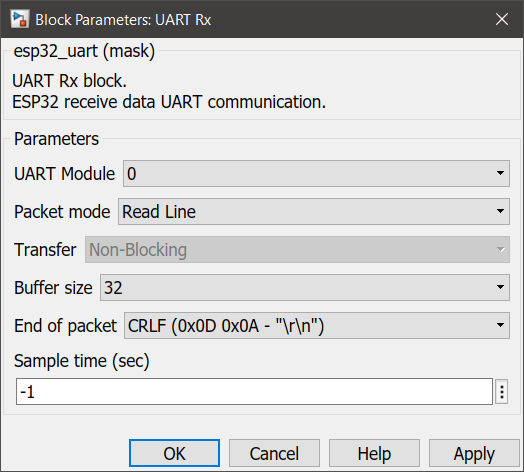
End of packet |
CR--LF--CRLF |
Terminator in ASCII mode is used to detect the end of the packet. The block will continue to receive ASCII and store it in a buffer, and detect terminator at the same time. After finding and matching the terminator, the block will perform the sscanf function to extract the value in a packet. |
Binary header |
Specify the Header pattern of the packet to receive |
This header is used for packet synchronization, the block will continue searching for the header, once the header is matched then the next bytes will be data. |
Binary terminator |
Specify the terminator pattern of the packet to receive |
This terminator is used for packet validation, once the header is matched and all data types are received, the next bytes will be terminator. if the terminator is not matched, the block will reject the previous bytes (Header and data), and continue searching for a new packet starting with header again. |
Number of data port, Type UINT8 |
Number of data type uint8 in packet |
1 data port of this data type contains 1byte in the packet. |
Sample time (sec) |
-1 (inherited) or specify |
Specify the sample time. |
When to use these blocks?
1.UART SETUP - The block must be placed into a Simulink model to enable/ configure the selected UART module when the application needs to send or receive data from an external device using the UART protocol.
2.UART TX - Use this block to transmit data from UART when an application needs communication between the device to device via UART protocol.
3.UART RX - Use this block to receive data from UART when an application needs communication between the device to device via UART protocol.
How do these blocks work?
UART SETUP
The following overview describes how to establish communication between an ESP32 and other UART devices using the functions and data types of the UART driver. The overview reflects a typical programming workflow and is broken down into the sections provided below:
1.Setting Communication Parameters - Setting baud rate, data bits, stop bits, etc.
2.Setting Communication Pins - Assigning pins for connection to a device.
3.Driver Installation - Allocating ESP32’s resources for the UART driver.
4.Running UART Communication - Sending / receiving data
5.Using Interrupts - Triggering interrupts on specific communication events
6.Deleting a Driver - Freeing allocated resources if a UART communication is no longer required
UART TX
The block will transmit data from the selected UART module depending on the configurations selected by the user.
UART RX
The block will receive data from the selected UART module buffer and process the packet depending on the configurations selected by the user.
Demo
Demo file : esp32_uart_demo.slx
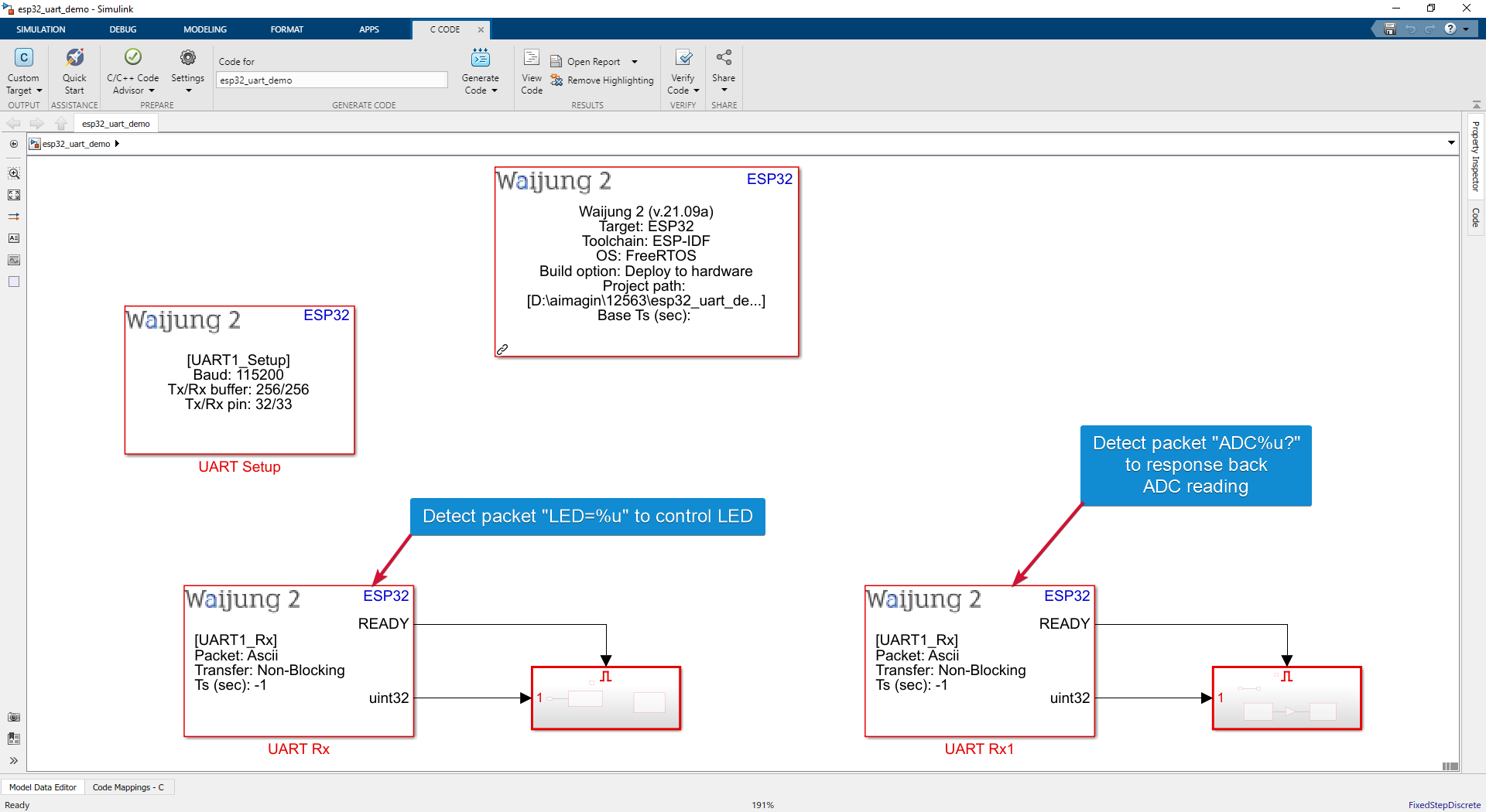
Description
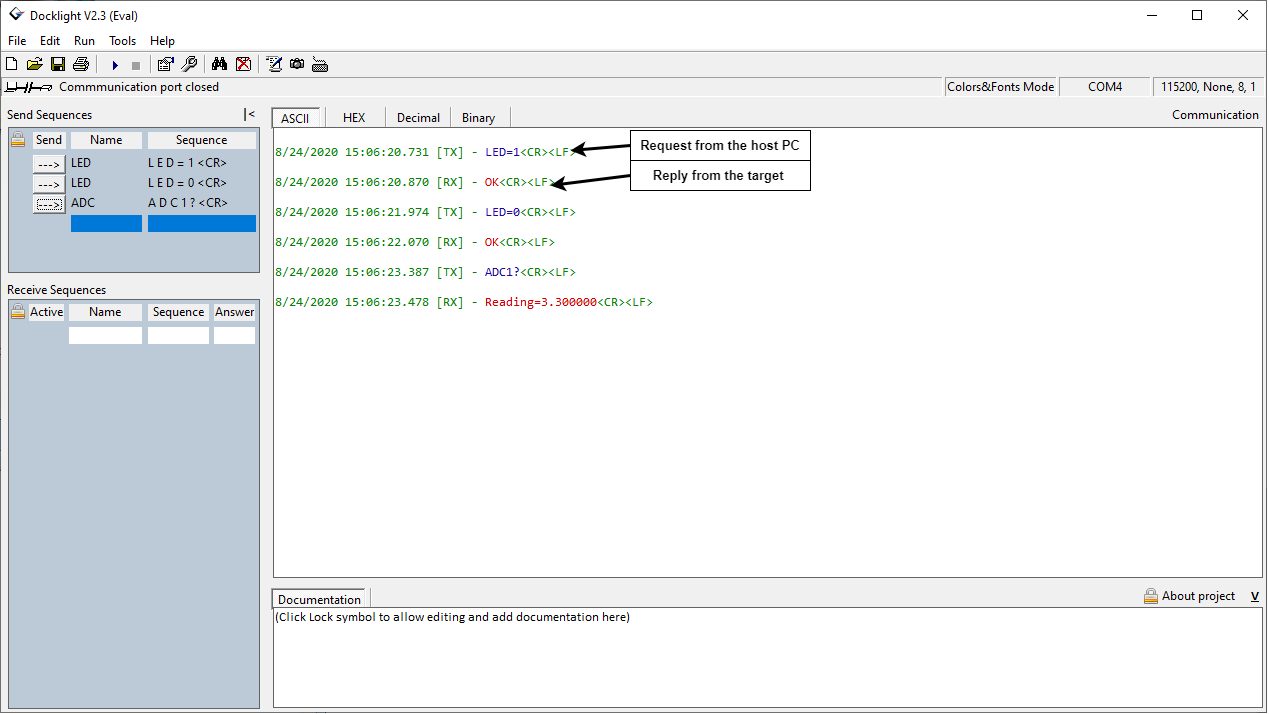
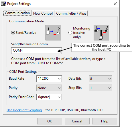
This demo shows the UART communication between the host pc and the target ESP32 using UART blocks. The user can send the string data (commands) to control or quarry data from ESP32 via COM port.
Software Setup
In this demo, the Docklight software is used to monitor the transmitted and received data from the host computer. The software can be downloaded from this link https://docklight.de/downloads/. The serial port configuration for this software is as below.
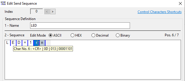
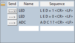
The transmitting data from the host computer
Commands in docklight
1.LED=1(press ctrl+enter to enter 'r' aka <CR>)(press ctrl+shift+enter to enter 'n' a.k.a. <LF>)
2.LED=0(press ctrl+enter to enter 'r' aka <CR>)(press ctrl+shift+enter to enter 'n' a.k.a. <LF>)
3.ADC1?(press ctrl+enter to enter 'r' aka <CR>)(press ctrl+shift+enter to enter 'n' a.k.a. <LF>)

Hardware Setup
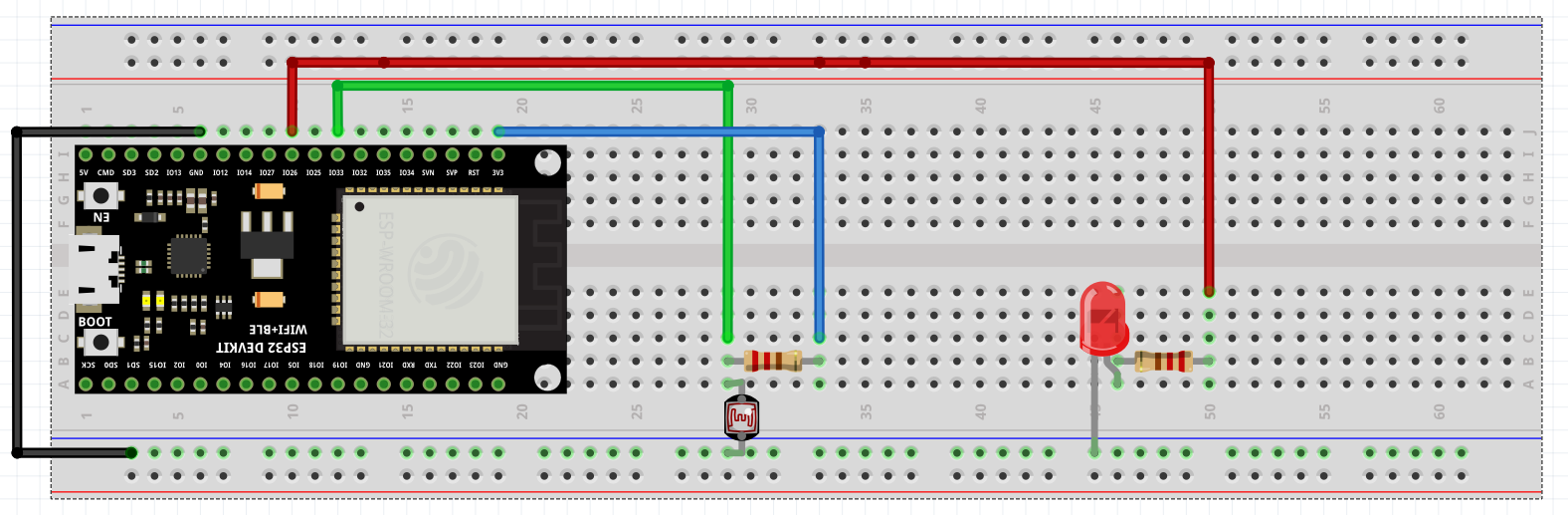
Note:
USB to UART converter is only needed when using UART modules other than UART0. UART0 is connected to serial programming port so only Tx and Rx pins need to be inputted. For our ESP32-WROOM development board, Tx and Rx pins are 1 and 3, respectively.
What should be happening?
There will be a response from the target module for each command from the host PC. For the command
•LED=1, response will be 'OK' and the GPIO26 will be HIGH
•LED=0 , response will be 'OK' and the GPIO26 will be LOW
•ADC1?, response will be the reading from the ADC pin in voltage