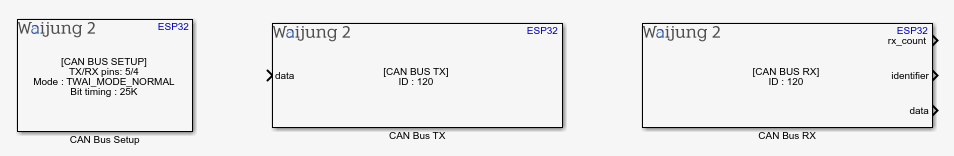
How do these blocks appear in a Simulink model?
What can be configured?
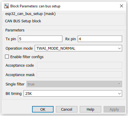
CAN BUS Setup
Configuration Parameter |
Selectable Option/Value |
Description |
Tx pin |
|
Enter CAN bus Tx pin |
Rx pin |
|
Enter CAN bus Rx pin |
Operation mode |
TWAI_MODE_NORMAL--TWAI_MODE_NO_ACK--TWAI_MODE_LISTEN_ONLY |
TWAI Controller operating modes TWAI_MODE_NORMAL - Normal operating mode TWAI_MODE_NO_ACK - Transmission does not require acknowledgment TWAI_MODE_LISTEN_ONLY - The TWAI controller will only receive messages |
Enable filter |
Check--Uncheck |
Check to filter messages |
Acceptance code |
|
Specifies the bit sequence which a message’s ID, RTR, and data bytes must match in order for the message to be received by the TWAI controller |
Acceptance mask |
|
Specifies the bit sequence which bits of the acceptance code can be ignored |
Single filter |
true--false |
Select single filter or dual filter. Look for more details in the expressif documentation |
Bit timing |
25K--50K--100K--125K--250K--500K--800K--1M |
Operating bit rate |
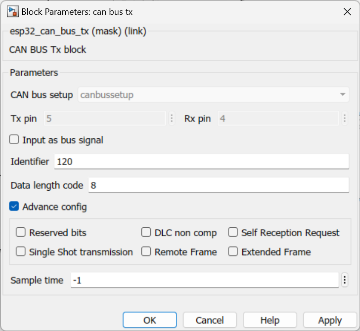
CAN BUS Tx
Configuration Parameter |
Selectable Option/Value |
Description |
Input as bus signal |
Check--Uncheck |
Iutput as Matlab CAN bus signal |
Identifier |
|
Enter identifier |
Data length code |
|
Enter dlc |
Advance config |
Check--Uncheck |
Input as bus signal should be unchecked, This will allows user to choose bellow params |
Reserved bits--DLC non comp--Self Reception Request--Single Shot transmission--Remote Frame--Extended Frame |
Check--Uncheck |
Check to output each data from the CAN message. |
Sample time |
-1 (inherited) or specify |
Specify the sample time. |
INPUT/ OUTPUT Port
Port Name |
Port Type |
Date Type |
Description |
data |
Scalar |
uint8 |
Input data to data |
reserved |
Scalar |
uint32 |
Input data to reserved |
dlc_non_comp |
Scalar |
uint32 |
Input data to dlc_non_comp |
self |
Scalar |
uint32 |
Input data to self |
ss |
Scalar |
uint32 |
Input data to ss |
rtr |
Scalar |
uint32 |
Input data to rtr |
extd |
Scalar |
uint32 |
Input data to extd |
can_msg_bus |
BUS |
CAN_MESSAGE_BUS |
Input data as can msg bus |
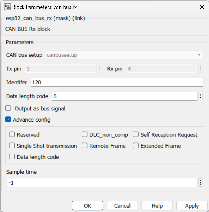
CAN BUS Rx
Configuration Parameter |
Selectable Option/Value |
Description |
Identifier |
|
Enter identifier to filter out from the received message |
Data length code |
|
Enter DLC for the received message |
Output as bus signal |
Check--Uncheck |
Output as Matlab CAN bus signal |
Advance config |
Check--Uncheck |
Output as bus signal should be unchecked, This will allows user to choose bellow params |
Reserved bits--DLC non comp--Self Reception Request--Single Shot transmission--Remote Frame--Extended Frame |
Check--Uncheck |
Check to output each data from the CAN message. |
Sample time |
-1 (inherited) or specify |
Specify the sample time. |
INPUT/ OUTPUT Port
Port Name |
Port Type |
Date Type |
Description |
identifier |
Scalar |
uint32 |
Output data to identifier |
dlc |
Scalar |
uint8 |
Output data to dlc |
data |
Scalar |
uint8 |
Output data to data |
reserved |
Scalar |
uint32 |
Output data to reserved |
dlc_non_comp |
Scalar |
uint32 |
Output data to dlc_non_comp |
self |
Scalar |
uint32 |
Output data to self |
ss |
Scalar |
uint32 |
Output data to ss |
rtr |
Scalar |
uint32 |
Output data to rtr |
extd |
Scalar |
uint32 |
Output data to extd |
can_msg_bus |
BUS |
CAN_MESSAGE_BUS |
Output data as can msg bus |
When to use these blocks?
1.CAN BUS Setup - The block must be placed into a Simulink model to enable/configure the CAN bus when the application needs to send or receive data from an external device using the CAN message.
2.CAN BUS Tx - Use this block to transmit data.
3.CAN BUS Rx - Use this block to receive data.
Note: External CAN transceiver required to transmit data.
How do these blocks work?
CAN BUS Setup : In the setup block Configuration & Installation of the drivers to support the CAN communication is be done.
CAN BUS Tx : The block will transmit CAN data.
CAN BUS Rx : The block will receive CAN data.
Demo
Tx Demo file : esp32_canbus_tx_demo.slx
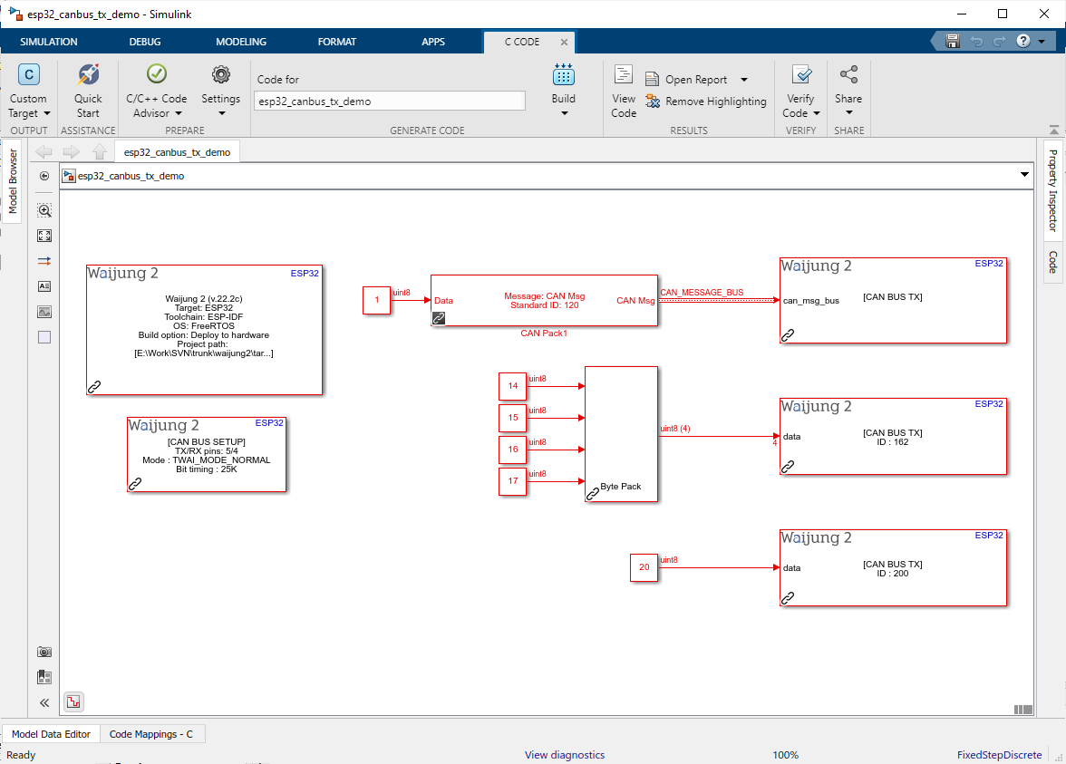
Description
This demo shows how the CAN Tx block can be used to transmit data to the can bus module. As in the example, there will be three messages transmitted every sample time. One use matlab can bus signal as an input, other two uses normal standard messages. Byte Pack block from matlab can be used to pack data bytes.
Rx Demo file : esp32_canbus_rx_demo.slx
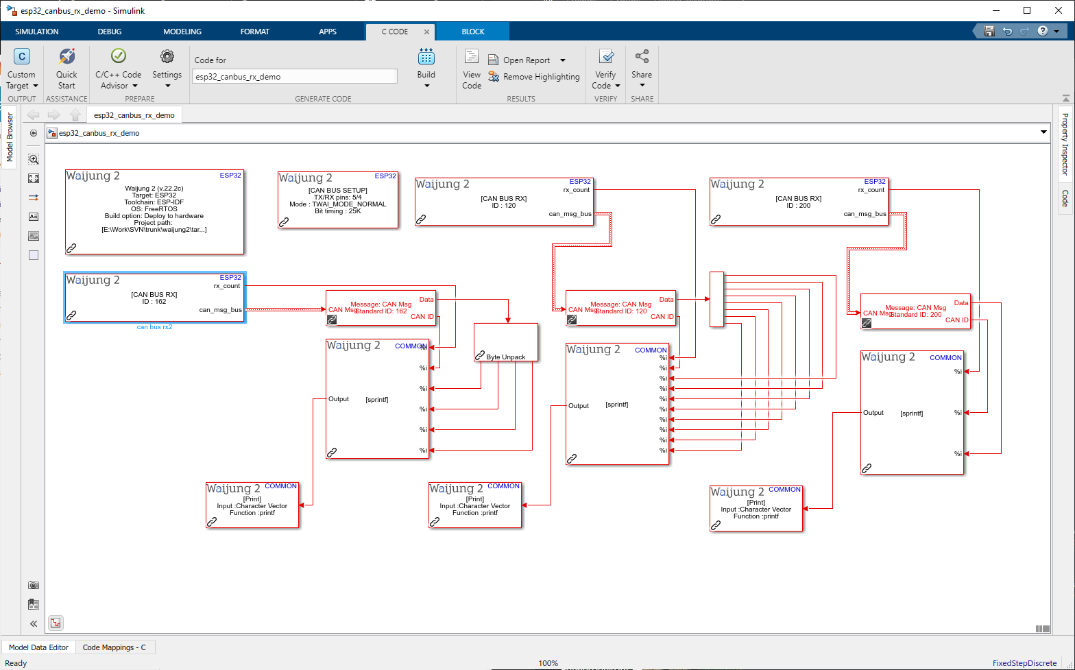
Description
This demo shows how CAN Rx block works. This will receive all 3 messages which sent from the previous example. RX counter will incremented every time if any value is received. Output will be given by every sample time.
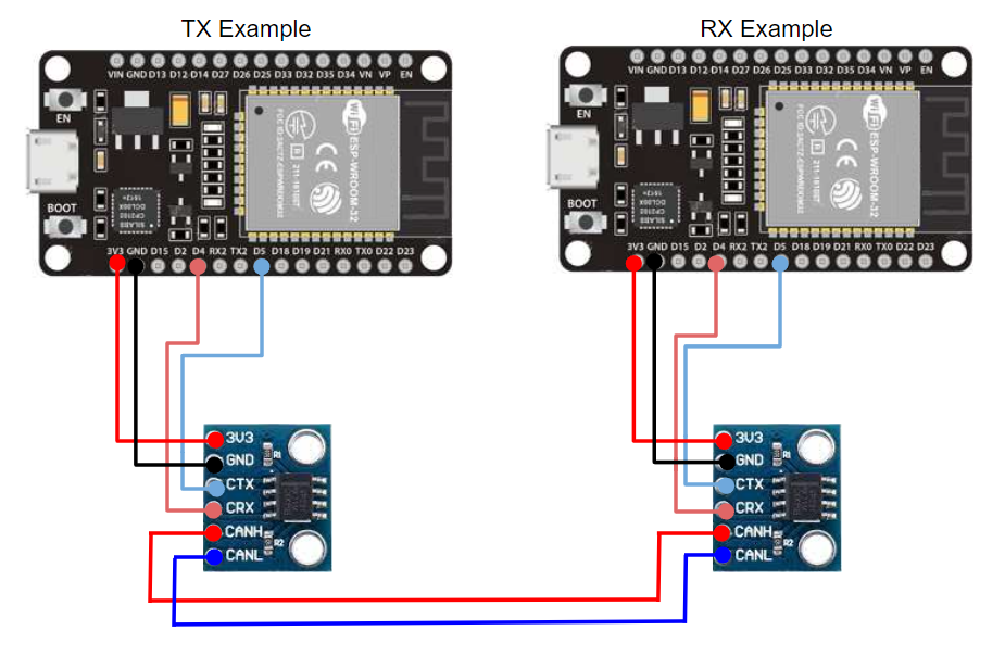
Hardware Setup
1.2 x ESP32 module
2.SN65HVD23x transceivers