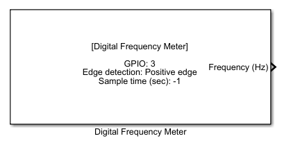
How this block appears in a Simulink model?
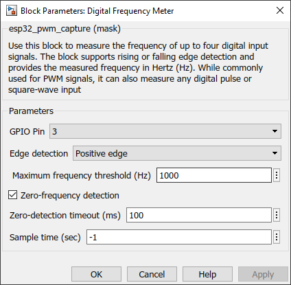
What can be configured?
Configuration Parameter |
Selectable Option/Value |
Description |
GPIO Pin |
All available GPIOs according to ESP32 family |
Select the input pin |
Edge detection |
Positive edge--Negative edge |
Select whether the block measures frequency using the signal’s rising (positive) edges or falling (negative) edges |
Maximum frequency threshold (Hz) |
- |
Defines the highest expected frequency that the block will measure. If the input signal exceeds this threshold, the block clamps or otherwise limits the measured value to avoid overflow or erroneous readings |
Zero-frequency detection |
Check--Uncheck |
Enables or disables the block’s ability to recognize when an input signal has effectively stopped toggling. When enabled, if no valid edges are detected within a predefined timeout period, the block reports 0 Hz to indicate that the signal frequency is zero. |
Zero-detection timeout (ms) |
- |
Define the timeout period to detect the Zero-frequency |
Sample time (sec) |
-1 (inherited) or specify |
Specify sample time for the block |
INPUT/ OUTPUT Port
Port Name |
Port Type |
Date Type |
Description |
Frequency (Hz) |
Scaler |
Single |
Outputs the measured frequency in Hz according to the input signal |
When to use this block?
Use the Digital Frequency Meter block whenever you need to measure the frequency of a digital or pulse-based signal on an ESP32 in real time. While it is particularly well-suited for reading PWM signals, it also works with any digital input that toggles between HIGH and LOW states.
How does this block work?
The block configures the ESP32’s internal timers or MCPWM capture units to detect digital signal transitions on a specified GPIO pin. Depending on your Edge detection parameter, it counts either rising or falling edges of the input signal.
Each time the selected edge occurs, the hardware capture notes the timestamp. The block’s underlying firmware then calculates the signal frequency by measuring the time difference between consecutive edges. This result is continuously updated and output in Hertz (Hz).
Limitations
This block doesn't support ESP32S2 and ESP32C3 families. The block supports measuring up to four independent digital signals simultaneously. The highest reliably measurable frequency depends on ESP32 clock speeds, timer resolution, and interrupt overhead. The block captures edges as they occur. If the input signal is noisy or contains spurious glitches, the measurement might be inaccurate.
Demo
Demo file : eps32_pwm_cap_demo.slx
Description
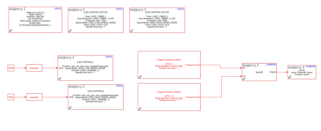
This demo model illustrates how to generate two PWM signals using the LEDC block and measure their frequencies in real time using the Digital Frequency Meter block. One LEDC channel is set to output a 1 kHz signal, while the other is set to 5 kHz. Each output is looped back into a corresponding GPIO input configured in the Digital Frequency Meter block, which then calculates the frequency and prints it to the serial monitor.
Hardware setup
•LEDC Output (1 kHz): GPIO 4 → Connect a jumper wire from GPIO 4 to GPIO 5.
•LEDC Output (5 kHz): GPIO 13 → Connect a jumper wire from GPIO 13 to GPIO 14.
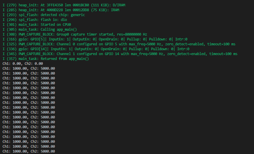
What should be happening?
The ESP32’s LEDC peripherals drive two PWM signals—one at ~1000 Hz, the other at ~5000 Hz. Each PWM output is physically fed into the Digital Frequency Meter’s input pins (GPIO 5 and GPIO 14). The Digital Frequency Meter block calculates the frequency of each channel and updates the values in the Simulink model every sample period. The measured frequencies are printed to the serial monitor.