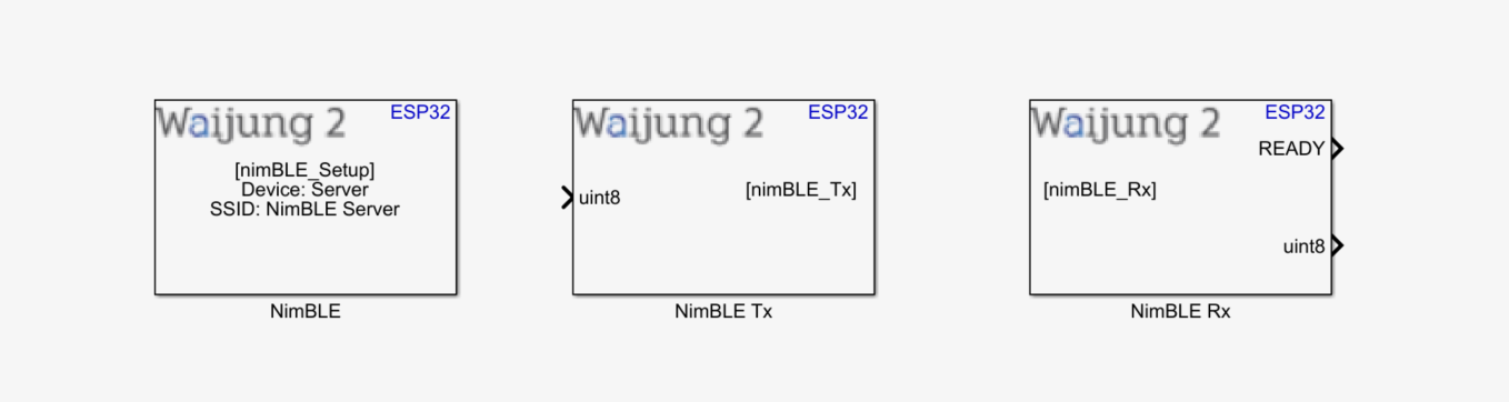
How this block appears in a Simulink model?
What can be configured?
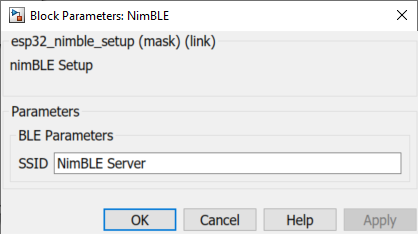
Nim-BLE Setup
Configuration Parameter |
Selectable Option/Value |
Description |
SSID |
|
Enter your preferred SSID |
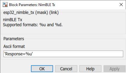
Nim-BLE Tx
Configuration Parameter |
Selectable Option/Value |
Description |
Ascii format |
|
Scanf format specifier, start with %. Below is supported by the block. %u : Output will be the type of uint8 %d: Output will be the type of int32 |
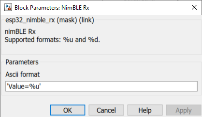
NimBLE Rx
Configuration Parameter |
Selectable Option/Value |
Description |
Ascii format |
|
Scanf format specifier, start with %. Below is supported by the block. %u : Input will be the type of uint8 %d: Input will be the type of int32 |
When to use this block?
1.NimBLE Setup - The block must be placed into a Simulink model to enable/ configure BLE server to send and receive data from an external device using the BLE (NimBLE) protocol.
2.NimBLE Tx - Use this block to transmit data via NimBLE protocol. The transmitted data can be checked from the client device using the 0xFEF4 Read attribute set by the NimBLE Setup.
3.NimBLE Rx - Use this block to receive data via NimBLE protocol. The data is sent from the client device using the 0xDEAD Write attribute set by the NimBLE Setup.
How does these blocks work?
The following overview describes how to establish communication between an ESP32 and a mobile BLE scanner application.
NimBLE Setup
Set up the desired SSID for the BLE server.
NimBLE Tx
The block will transmit data to the client, depending on the configurations selected by the user
NimBLE Rx
The block will receive data from the client and process the data packet depending on the configurations selected by the user.
Demo
Demo file : esp32_NimBLE_demo.slx
Description
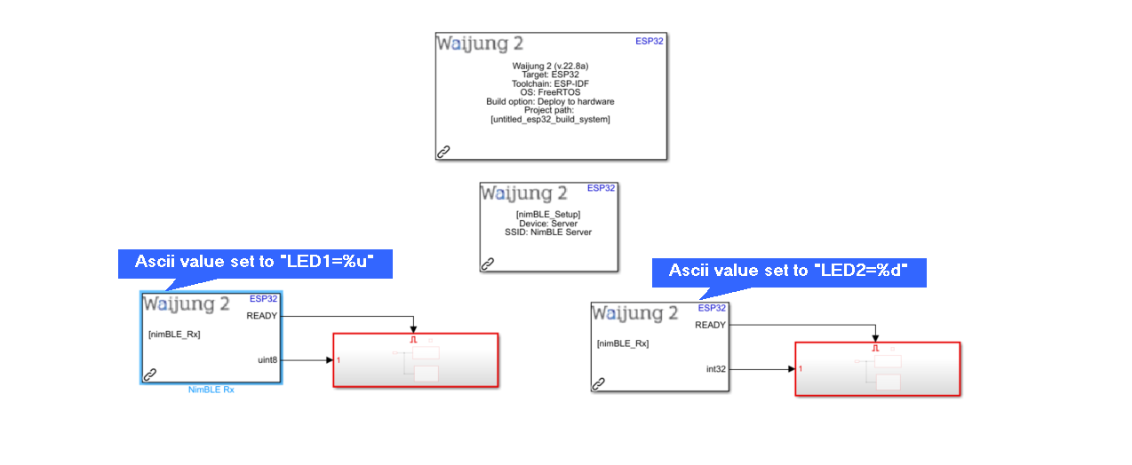
This demo shows how to establish communication between an ESP32 and a mobile BLE scanner application. For this example the "nRF Connect for Mobile" by Nordic Semiconductor ASA mobile application have been chosen. The user can send data in UTF8 format by using the mobile app to switch on/off LEDs attached to the ESP32 unit. There are two Rx blocks in the model where the first block is configured to listen to data sent by the user in the format of "LED1=%u", while the second block listens to data sent in the format of "LED2=%d".
Note: The "READY" output of the Rx block will be set to '1' only if the client sends correct prefix. For a wrong prefix, the "READY" will be set to '0'. For example, in this case Rx block 1 expects a prefix of "LED1" and Rx block 2 expects a prefix of "LED2". If the user sends a command which is mismatching to prefixes defined in the model, no subsystem will trigger. (Ex: Value=1, Val=1, Val1=1, etc).
Attached to the two blocks are two subsystems with similar functionality. Given below is subsystem 01.
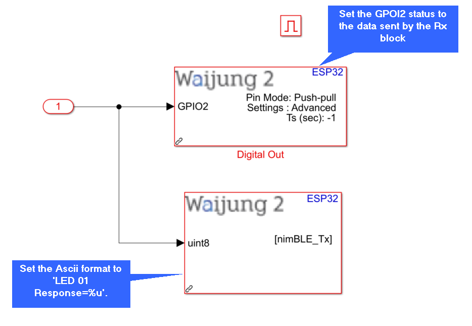
Consider the above subsystem 01 attached to Rx block 01, listening for "LED1=%u" events. In this subsystem, the output value from Rx block is taken in, and passed to Digital Out block where GPIO2 is selected. The Built-In LED (Assuming it is GPIO2 in your ESP32) will light up for any value except 0. The Tx block will take in the output value from the Rx block and send data to client as 'LED 01 Response=%u".
Mobile Application setup
1.From the play store (for Android) or the App store (for ios), download "nRF Connect for Mobile" by Nordic Semiconductor ASA.
2.Once downloaded, please enable blue-tooth in your phone.
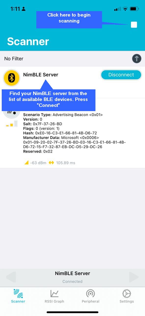
3.Once your ESP32 has the Simulink model uploaded, begin scanning for BLE devices from the app.
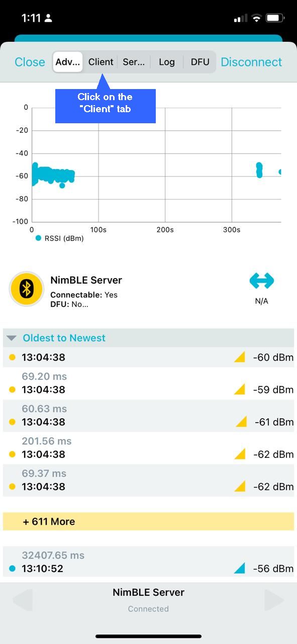
4.Find your NimBLE Server from the list and click on "Connect".
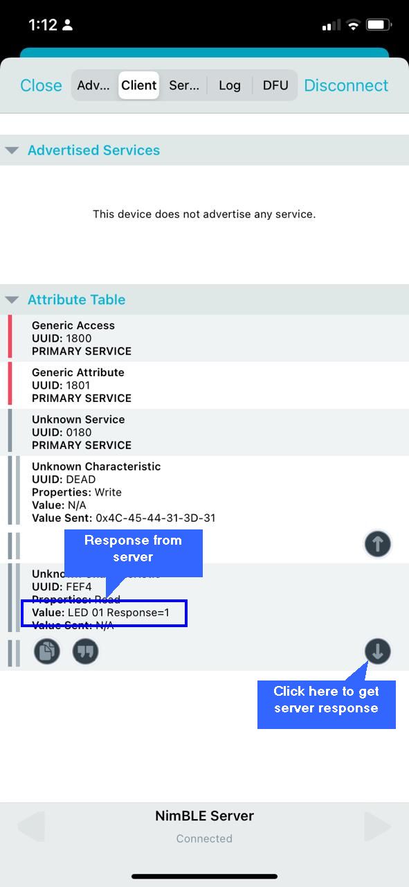
5.This will navigate you to the below window. From the tabs shown above, select "Client".
6.In the "Client" tab, you can see the attributes related to the NimBLE server. Here there are two attributes with the following services:
a.UUID = 0xDEAD is the service related to writing information to the Server.
b.UUID = 0xFEF4 is the service related to reading information from the Server.
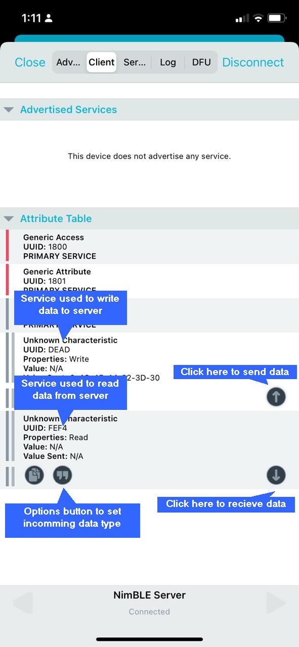
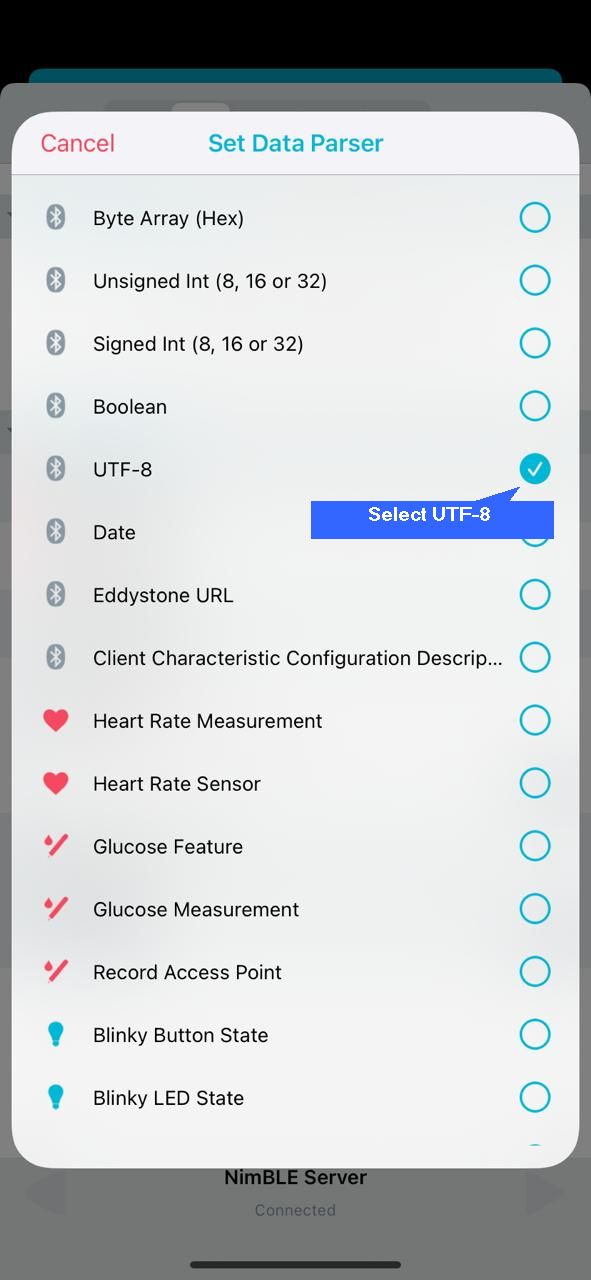
7.Before reading information sent from the server, please click on "options" button in the Read service, and set the data parser as "UTF-8".
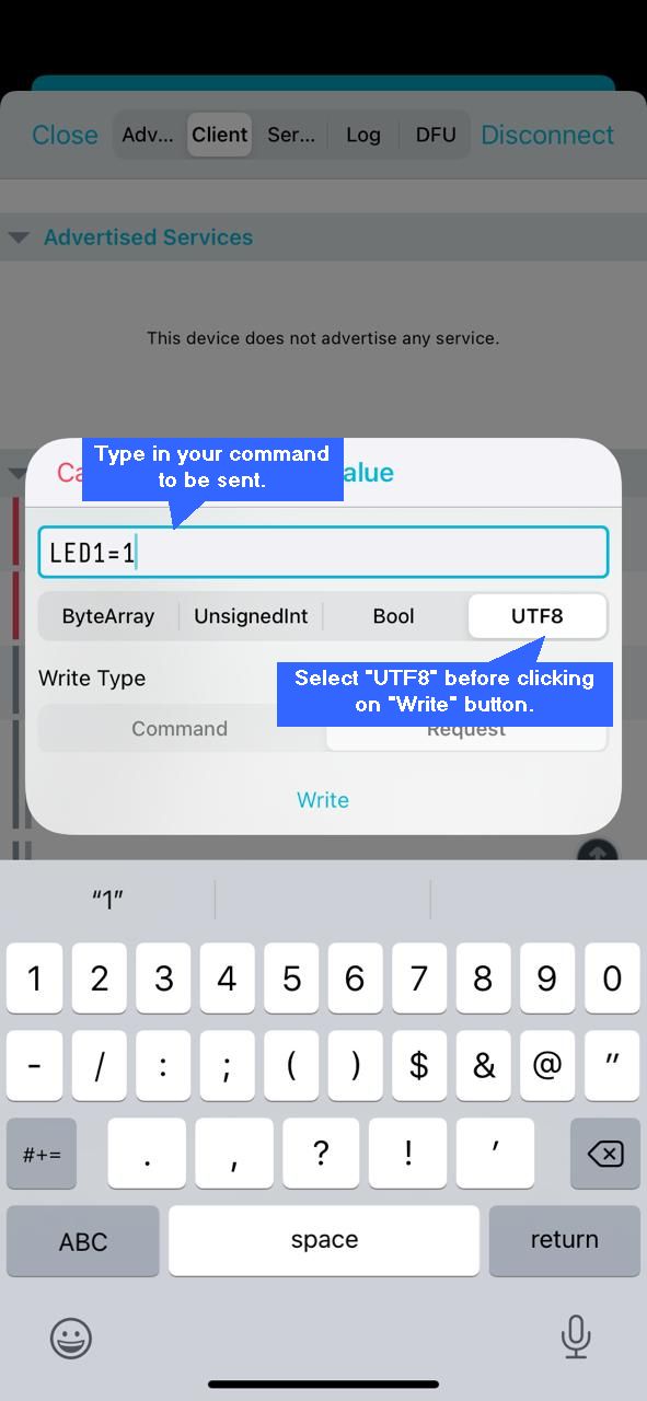
8.Now you are ready to send data to server. To send data, please click on the "Up-Arrow" key in the Write service attribute. Type in your required data and select "UTF8" before clicking on the "Write" button.
Hardware setup
1. ESP32 module
2. Mobile phone
3. Host PC
What should be happening?
There will be LED switch on/off event occurring when user sends data in the correct format. The events are listed below:
1.When the user sends "LED1=1" the GPIO2 will be HIGH. Response from server: 'LED 01 Response=1'
2.When the user sends "LED1=0" the GPIO2 will be LOW. Response from server: 'LED 01 Response=0'
3.When the user sends "LED2=1" the GPIO5 will be HIGH. Response from server: 'LED 02 Response=1'
4.When the user sends "LED2=0" the GPIO5 will be LOW. Response from server: 'LED 02 Response=0'
5.Note: To read the server response please click on the "Down-arrow" key in the Read service.