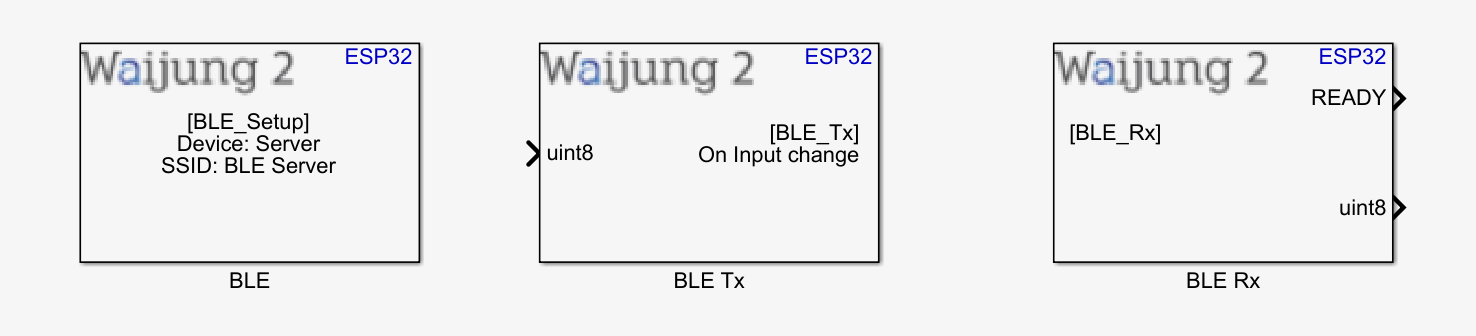
How this block appears in a Simulink model?
What can be configured?
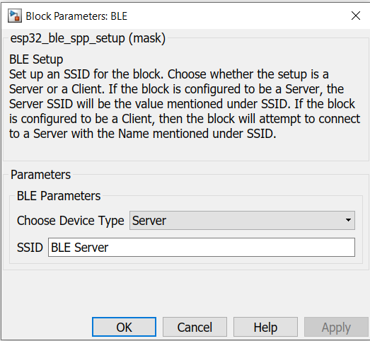
SPP-BLE Setup
Configuration Parameter |
Selectable Option/Value |
Description |
Choose Device Type |
Server/ Client |
Selects the operation of the BLE setup block. |
SSID |
|
Enter your preferred SSID |
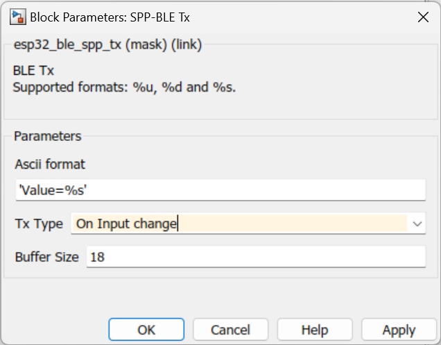
SPP-BLE Tx
Configuration Parameter |
Selectable Option/Value |
Description |
Ascii format |
|
Scanf format specifier, start with %. Below is supported by the block. %u : Output will be the type of uint8 %d: Output will be the type of int32 %s: Output will be the type of uint8 array. (Once %s is set, please enter the required buffer size in the "Buffer size" field, now visible.) |
Tx Type |
On Input change/ Consistent |
On Input change: The Tx block will send data only if the input value had changed since the previous transmission of data.
Consistent: The Tx block will continuously send data at the base sample time of the model. |
Buffer size |
|
Buffer size of the sending data |
SPP-BLE Rx
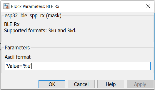
Configuration Parameter |
Selectable Option/Value |
Description |
Ascii format |
|
Scanf format specifier, start with %. Below is supported by the block. %u : Input will be the type of uint8 %d: Input will be the type of int32 %s: Output will be the type of uint8 array. (Once %s is set, please enter the required buffer size in the "Buffer size" field, now visible.) |
When to use this block?
1.SPP-BLE Setup - The block must be placed into a Simulink model to enable/ configure BLE Server/ Client to send and receive data from an external device using the BLE-SPP protocol.
2.SPP-BLE Tx - Use this block to transmit data via BLE-SPP protocol.
3.SPP-BLE Rx - Use this block to receive data via BLE-SPP protocol.
How does these blocks work?
The following overview describes how to establish communication between two ESP32 devices and a mobile BLE scanner application.
SPP-BLE Setup
Set up the desired SSID for the SPP-BLE Server/ Client.
SPP-BLE Tx
The block will transmit data to the client, depending on the configurations selected by the user
SPP-BLE Rx
The block will receive data from the client and process the data packet depending on the configurations selected by the user.
Demo 01: SPP-BLE connection between Server and BLE Scanner Application
Demo File: esp32_BLE_Server_Demo.slx
Description
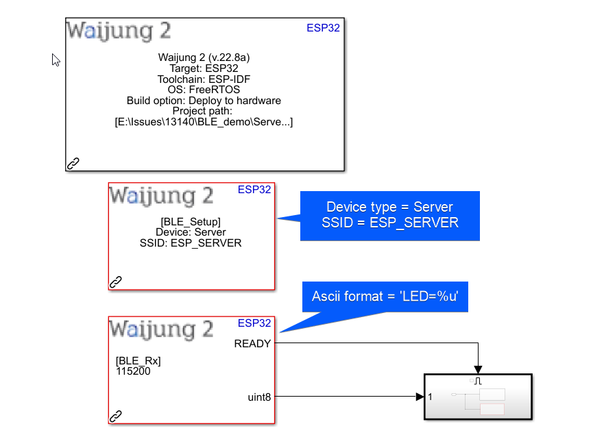
For this demo, please use the "esp32_BLE_Server_Demo.slx" model.
This demo shows how to establish communication between an ESP32 and a mobile BLE scanner application. For this example the "nRF Connect for Mobile" by Nordic Semiconductor ASA mobile application have been chosen. The user can send data in UTF8 format by using the mobile app to switch on/off LED attached to the ESP32 unit. The Rx block in the model is configured to listen to data sent by the user in the format of "LED=%u".
Note: The "READY" output of the Rx block will be set to '1' only if the client sends correct prefix. For a wrong prefix, the "READY" will be set to '0'. For example, in this case the Rx block expects a prefix of "LED". If the user sends a command which is mismatching to prefixes defined in the model, no subsystem will trigger. (Ex: Value=1, Val=1, Val1=1, etc).
Attached to the Rx block is the subsystem to light up LED. Given below is the subsystem:
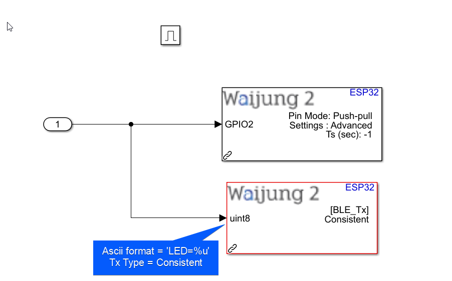
Consider the above subsystem attached to Rx block, listening for "LED=%u" events. In this subsystem, the output value from Rx block is taken in, and passed to Digital Out block where GPIO2 is selected. The Built-In LED (Assuming it is GPIO2 in your ESP32) will light up for any value except 0. The Tx block will take in the output value from the Rx block and send data to client as 'LED=%u".
Mobile Application setup
1.From the play store (for Android) or the App store (for ios), download "nRF Connect for Mobile" by Nordic Semiconductor ASA.
2.Once downloaded, please enable blue-tooth in your phone.
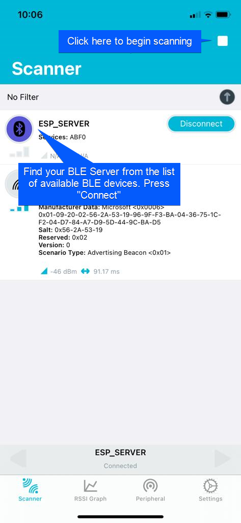
3.Once your ESP32 has the Simulink model uploaded, begin scanning for BLE devices from the app.
4.Find your BLE Server from the list and click on "Connect".
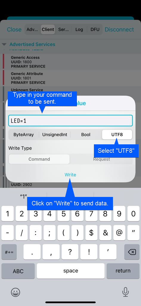
5.This will navigate you to the below window. From the tabs shown above, select "Client".
6.In the "Client" tab, you can see the attributes related to the BLE server. The required service for the example is UUID: ABF3
7.Now you are ready to send data to server. To send data, please click on the "Up-Arrow" key in the Write service attribute. Type in your required data and select "UTF8" before clicking on the "Write" button.
Hardware setup
1. ESP32 module configured as the Server.
2. Mobile phone with "nRF Connect for Mobile" by Nordic Semiconductor ASA mobile application installed.
3. Host PC.
What should be happening?
There will be LED switch on/off event occurring when user sends data in the correct format. The events are listed below:
1.When the user sends "LED=1" the GPIO2 will be HIGH.
2.When the user sends "LED=0" the GPIO2 will be LOW.
Demo 02: SPP-BLE connection between two ESP32 devices
Demo File: esp32_BLE_Client_Demo.slx
Description
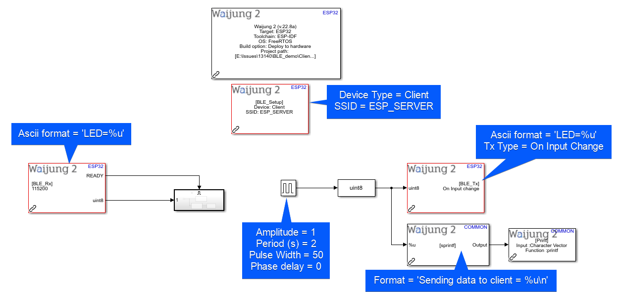
For this demo, please use the already configured ESP32 device from the Demo 01 as the Server. For the client, please use the "esp32_BLE_Client_Demo.slx" model. Use a separate ESP32 device to build the model. Given below is the description for the client model. The sample time of the model is governed by the pulse generator which have a sample time of 1 second. Therefore every 1 second, the Tx block will be triggered to send data to Server. A serial statement will be printed out when sending data.
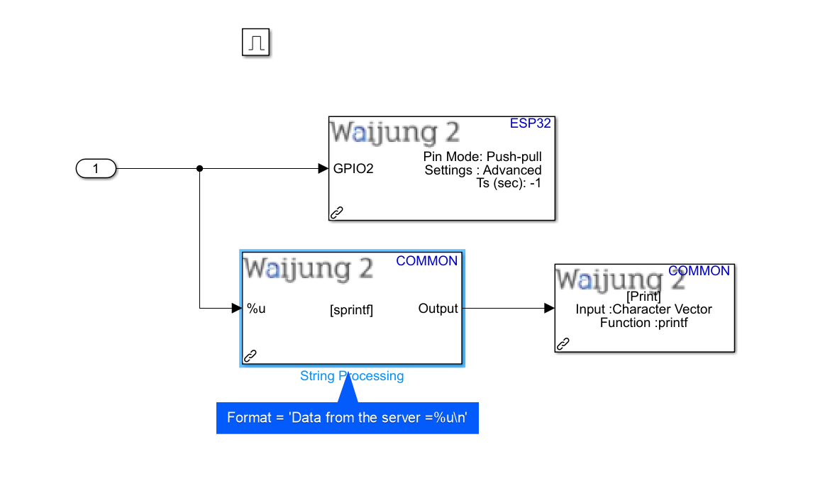
When data is received by the Client through the Rx block, the below subsystem will be triggered. It will set the GPIO pin to the received value and print out a serial statement containing information about the received data.
Hardware setup
1. ESP32 module configured as the Server.
2. ESP32 module configured as the Client.
3. Host PC.
What should be happening?
1. Once proper communication connection is built between the Server and Client, the LED attached to the GPIO2 pin of both the Server and Client ESP devices will begin to toggle on and off.
2. When the LED of the Server is at the "ON" state, the LED of the Client will be at "OFF" state, and vice-versa.
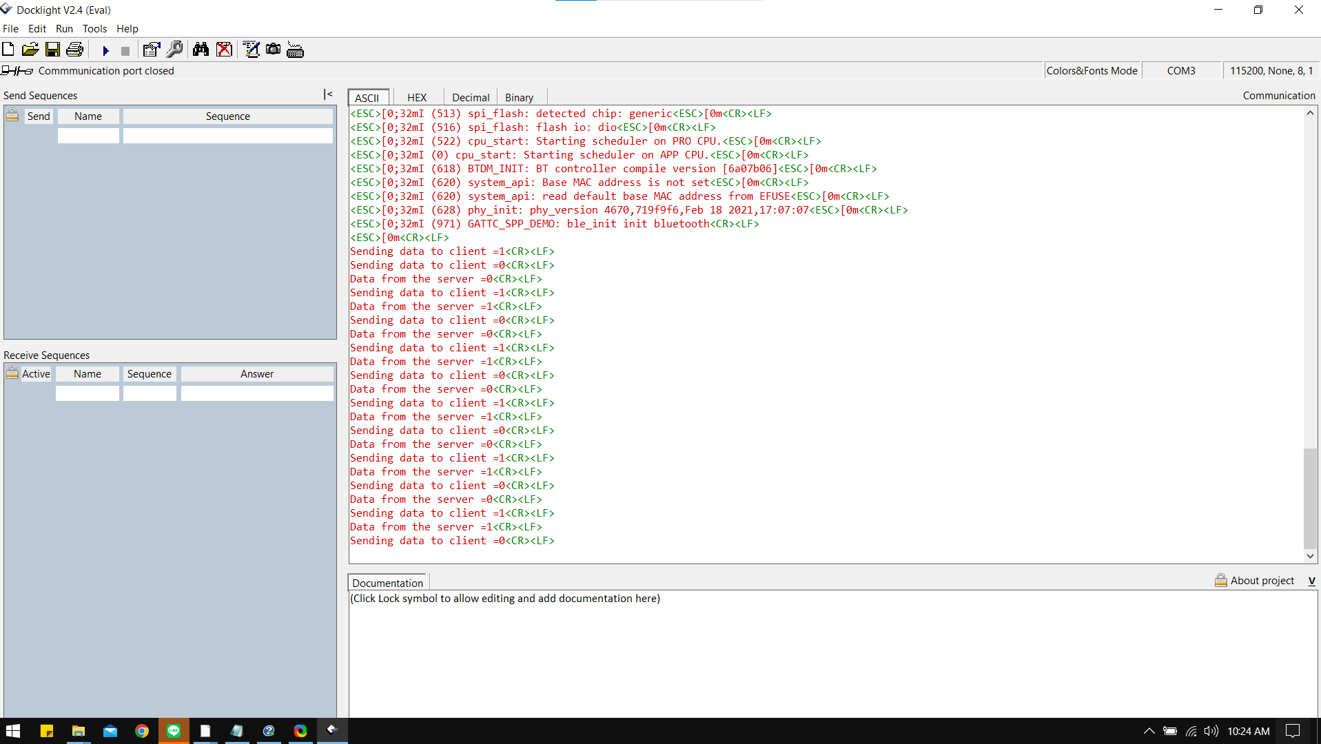
3. The Serial monitor attached to the Client will display the occurring events as shown below:
Demo 03: SPP-BLE send information in %s format from Server to Client
Demo File: BLE_Demo_03.zip
Description
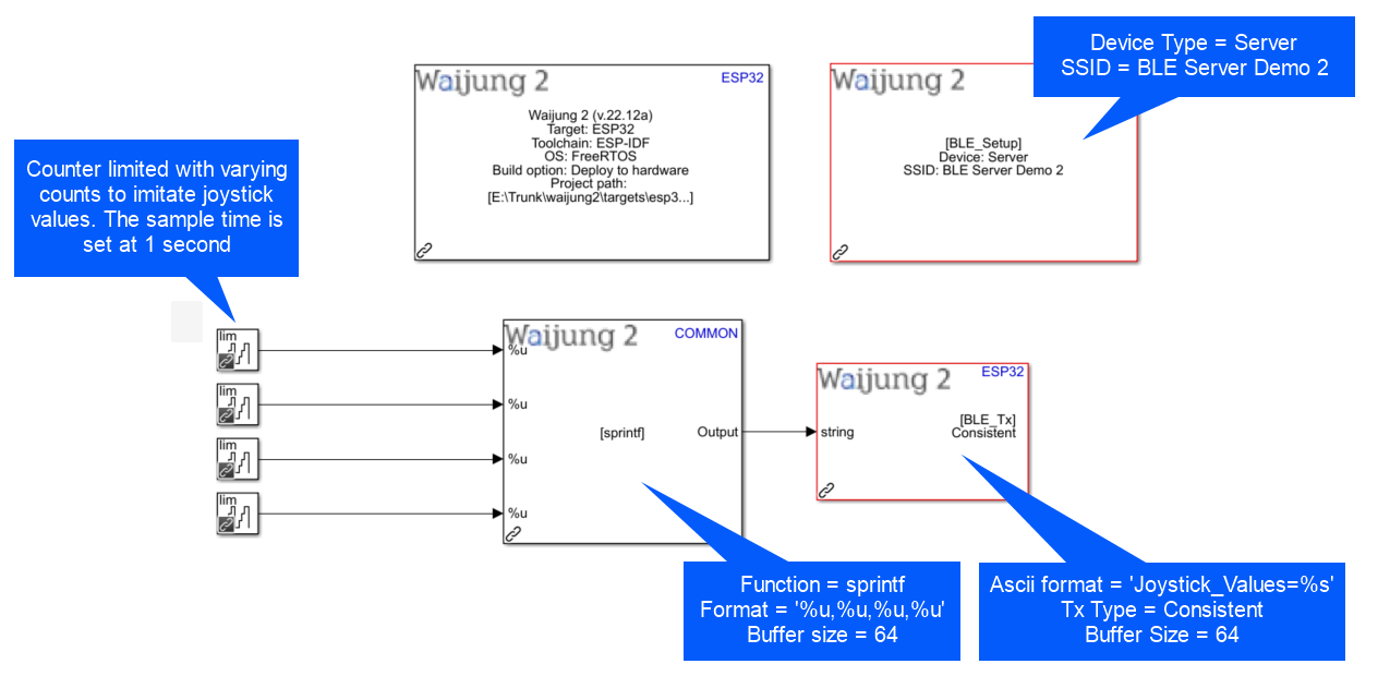
For this demo, extract the above zip file, upload the "esp32_BLE_Client_Demo_03.slx" to the ESP32 device to be setup as the client. Upload the "esp32_BLE_Server_Demo_03.slx" to the ESP32 device to be setup as the server. Given below is the description for the server model. The Server will attempt to send four %u values at once to the client.
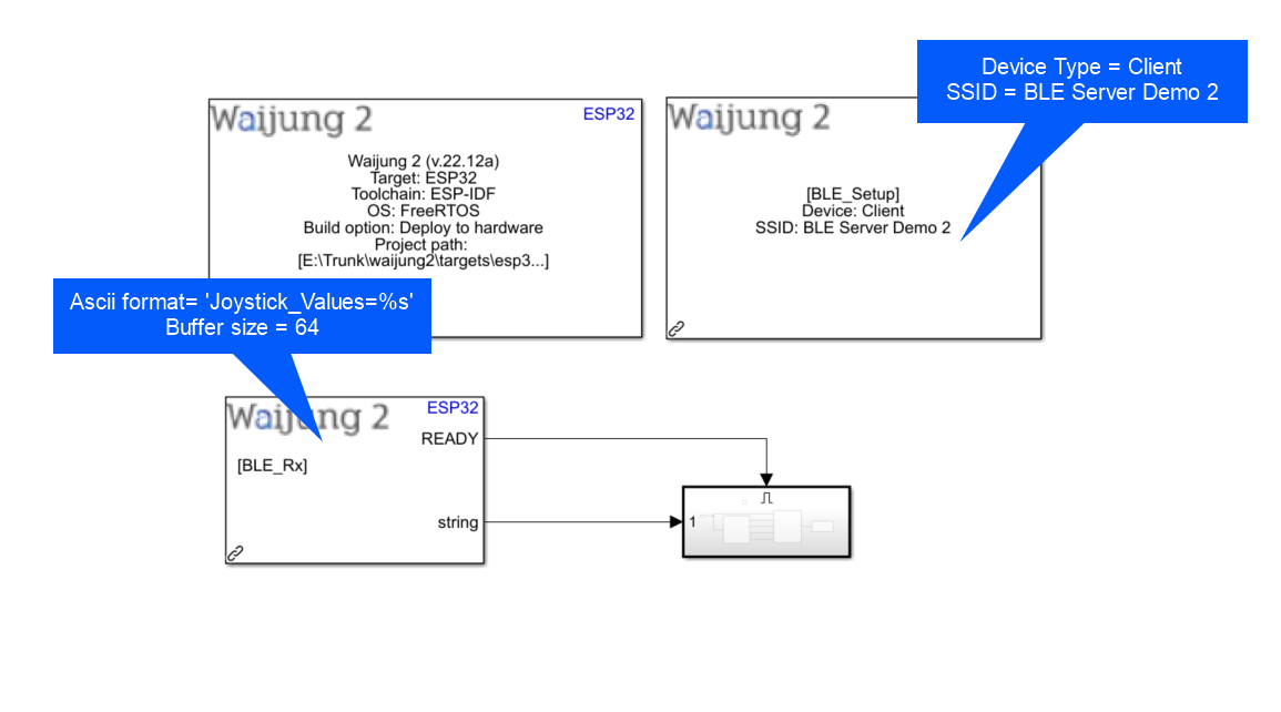
The client model is shown below. Here, the BLE Rx will be listening to messages from Server, and if the recieved messages fits the Rx criteria (Joystick_Values=%s), then the enabled subsystem is triggered.
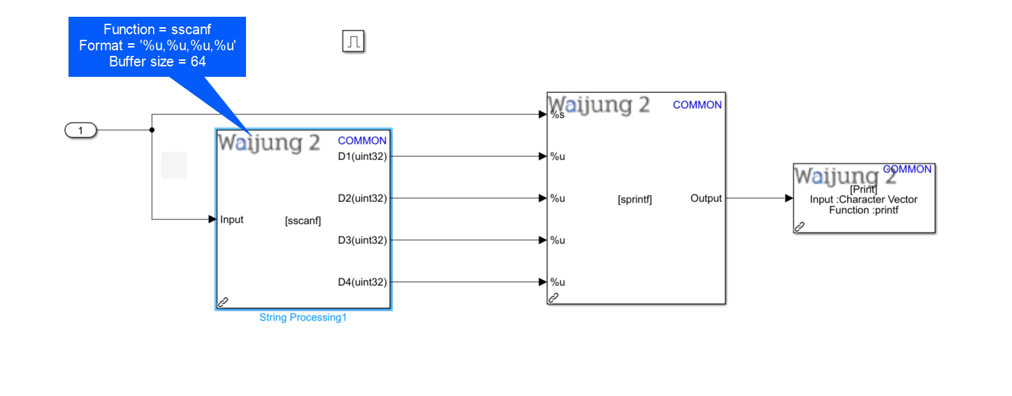
In the enabled subsystem, the individual values are decoded by using the string processing block as shown below.
Hardware setup
1. ESP32 module configured as the Server.
2. ESP32 module configured as the Client.
3. Host PC.
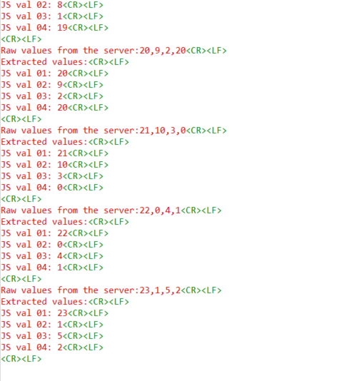
What should be happening?
1. Once proper communication connection is built between the Server and Client, the client will print out the below messages from the serial monitor. Here, the raw data coming from the Server is printed and then the extracted information is also printed.