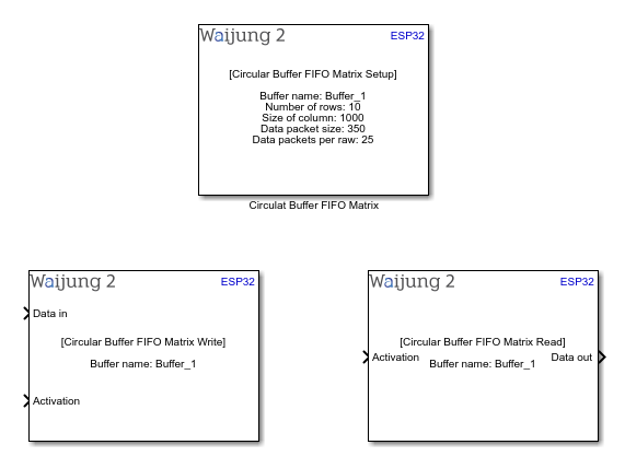
How this block appears in a Simulink model?
What can be configured?
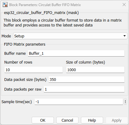
Setup Block
Configuration Parameter |
Selectable Option/Value |
Description |
Mode |
Setup |
Select the operation mode |
Buffer name |
|
Allocate a name for the circular buffer FIFO matrix |
Number of rows |
|
Number of rows in matrix buffer |
Size of column (bytes) |
|
Maximum size of the data expect to store in column in FIFO matrix |
Data packet size (bytes) |
|
Size of one data packet which going store in column |
Data packets per raw |
|
Number of data packets expect to store in raw |
Sample time (sec) |
-1(inherited) or specify |
Specify the sample time |
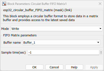
Write Block
Configuration Parameter |
Selectable Option/Value |
Description |
Mode |
Write |
Select the operation mode |
Buffer name |
|
Select the buffer name which you given in the Setup block |
Sample time (sec) |
-1(inherited) or specify |
Specify the sample time |
INPUT Port
Port Name |
Port Type |
Date Type |
Description |
Data in |
Vector |
uint8 |
Feed char vector with the data to be stored |
Activation |
Scalar |
Boolean |
Set activation status to high to store data in the FIFO matrix buffer |
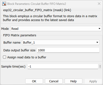
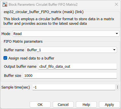
Read Block
Configuration Parameter |
Selectable Option/Value |
Description |
Mode |
Read |
Select the operation mode |
Buffer name |
|
Select the buffer name which you given in the Setup block |
Data output buffer size |
Check--Uncheck |
Assign output port buffer size |
Assign read data to a buffer |
Check--Uncheck |
Enable to assign read data to a common buffer |
Output buffer name |
|
Assign a name for common buffer |
Buffer size |
|
Size of common buffer |
Sample time (sec) |
-1(inherited) or specify |
Specify the sample time |
INPUT Port
Port Name |
Port Type |
Date Type |
Description |
Activation |
Scalar |
Boolean |
Set activation status to high to read data from the FIFO matrix buffer. if it set to low that mean it does read data from FIFO matrix buffer |
OUTPUT Port
Port Name |
Port Type |
Date Type |
Description |
Data out |
Vector |
uint8 |
The port outputs a vector with the data that read from the FIFO matrix |
When to use this block?
This block functions as an effective means of storing data within a matrix buffer, following a First In First Out (FIFO) principle. Through this methodology, data is systematically organized in a FIFO cycle, where incoming information is added while concurrently shifting existing data by one position. Consequently, the oldest data is gradually phased out as the buffer size dictates. The primary purpose of this buffer mechanism is to uphold the most current data within an application.By employing this FIFO circular approach, memory usage is streamlined, and the need for frequent memory reallocation is mitigated. This design permits the continuous recording or processing of data, optimizing operational efficiency without necessitating excessive memory adjustments.
How does this block work?
Once you define parameters of the setup block the matrix creates depending on the given settings.Lets consider following as an example.

In the given configuration, the matrix has 10 rows, each with columns capable of storing up to 1000 bytes. The arrangement specifies one data packet per row, and each packet can be as large as 350 bytes. This design ensures that a single data packet is accommodated in each row.The process involves transmitting a JSON packet, which adheres to the size limit of 350 bytes outlined in the setup section. It's important to note that these settings are adjustable to match specific requirements, and the mentioned configuration is solely an illustrative example.Once these settings are configured, you can conceptualize the creation of the buffer within the code. This visualization corresponds to the image provided, helping you better understand the internal buffer structure.
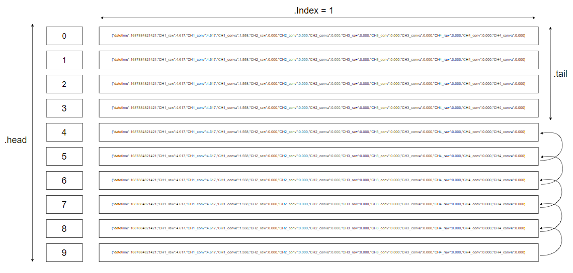
The image presented illustrates the operation whereby a JSON packet is introduced into the input port of the write block. The matrix then proceeds to store this packet by incrementing its header value. Upon reaching a header value of 9, the data undergoes a shifting process, with all entries shifting by one position, and the latest packet finding its place in the last position. Subsequently, when new data is introduced through the input port, the entire data set shifts by one position again, and the most recent data occupies the final slot. This mechanism follows the FIFO concept, resulting in the gradual removal of the oldest data from the buffer.
This cyclic behavior guarantees an efficient process of data storage and replacement. Upon executing the read block, all previously unread data is retrieved and presented as a unified entity, with each datum separated by commas. To attain a more comprehensive understanding of this sequence, highly recommend engaging with the provided demo. It will furnish you with practical insights into the operational dynamics of this buffer system.
Demo
Write data and read data from circular buffer FIFO matrix
Demo1 file: esp32_cbuf_FIFO_matrix_demo1.slx
Demo 1 : Write data and read data from circular buffer FIFO matrix
Description
This example serves as an educational tool to showcase the operational dynamics of circular buffer FIFO matrix blocks when executed within a singular task. The primary goal of this example is to facilitate a clear comprehension of the process of writing data into the block and subsequently reading data from it.
Full Model
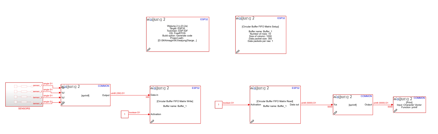
What should be happening?
Build the "demo1" file by compiling the provided demo file. Upon successful deployment of this file to the hardware, proceed to initiate the serial communication software for testing the aforementioned demo. In the software interface, choose the appropriate COM port to establish a connection for data monitoring.
Referring to the image above, you'll observe a comprehensive depiction of the process. This image illustrates the seamless flow of sensor data being written into the matrix buffer and subsequently read from it, all within the confines of a single task execution. This visual representation highlights the inherent efficiency of circular buffer FIFO matrix blocks in managing data operations.By following these steps, you will gain valuable hands-on experience in comprehending the real-world functioning of the circular buffer FIFO matrix blocks, solidifying your understanding of data writing and reading processes within a cohesive task environment.
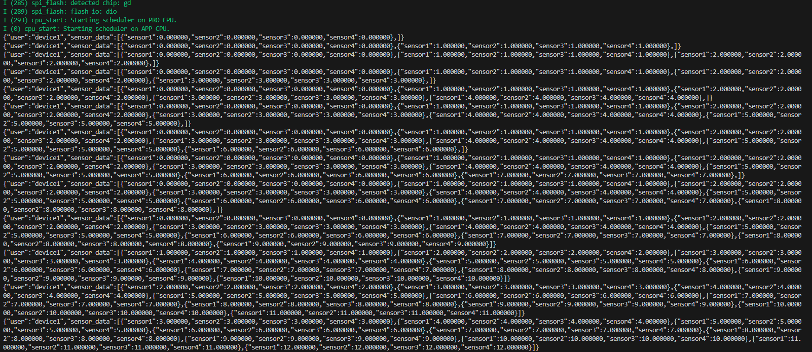
By analyzing the serial print data sequentially, a clear understanding of the operational process emerges. Given the buffer's configuration of 10 rows, the initial ten executions result in a gradual filling of each row, with one entry added per execution. Once these ten executions transpire, the buffer attains its full capacity.Subsequently, as new data continues to be added, a shift in positions occurs: all entries shift by one position, and the most recent data finds its place in the last row. This dynamic pattern persists, thereby facilitating a continuous cycle. The shifting process effectively maintains the buffer's content in accordance with the FIFO concept, with older data progressively being phased out.
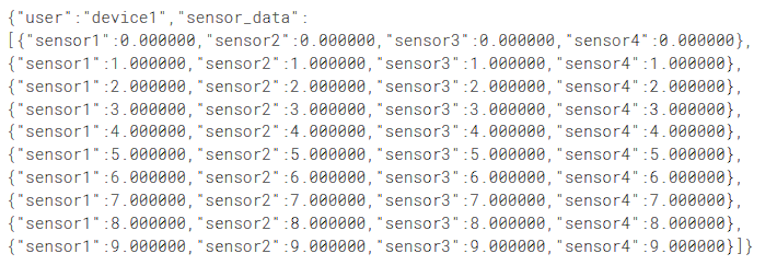
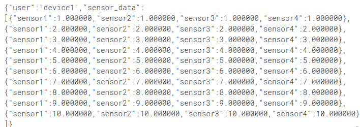
The image provided visually elucidates this shifting mechanism. By observing this representation, you can tangibly perceive how data shifts and relocates over the course of successive executions, contributing to a clearer grasp of the entire process.