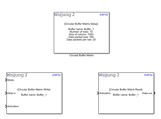
How this block appears in a Simulink model?
What can be configured?
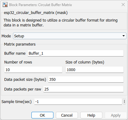
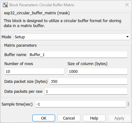
Setup Block
Configuration Parameter |
Selectable Option/Value |
Description |
Mode |
Setup |
Select the operation mode |
Buffer name |
|
Allocate a name for the circular buffer matrix |
Number of rows |
|
Number of rows in matrix buffer |
Size of column (bytes) |
|
Maximum size of the data expect to store in column in matrix |
Data packet size (bytes) |
|
Size of one data packet which going store in column |
Data packets per raw |
|
Number of data packets expect to store in raw |
Sample time (sec) |
-1(inherited) or specify |
Specify the sample time |
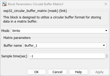
Write Block
Configuration Parameter |
Selectable Option/Value |
Description |
Mode |
Write |
Select the operation mode |
Buffer name |
|
Select the buffer name which you given in the Setup block |
Sample time (sec) |
-1(inherited) or specify |
Specify the sample time |
INPUT Port
Port Name |
Port Type |
Date Type |
Description |
Mode |
Scalar |
Boolean |
Mode = 0 means it store only one data packet per raw even though you set data packet per raw to a large number. Mode = 1 means it store data packets that equal to the setting you set in Setup block |
Data in |
Vector |
uint8 |
Feed char vector with the data to be stored |
Activation |
Scalar |
Boolean |
Set activation status to high to store data in the matrix buffer. if it set to low that mean it does store the data to the buffer |
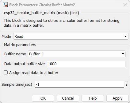
Read Block
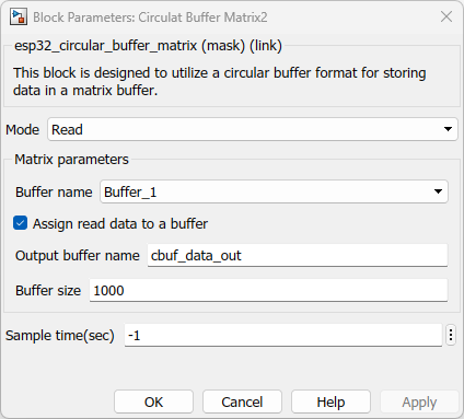
Configuration Parameter |
Selectable Option/Value |
Description |
Mode |
Read |
Select the operation mode |
Buffer name |
|
Select the buffer name which you given in the Setup block |
Data output buffer size |
Check--Uncheck |
Assign output port buffer size |
Assign read data to a buffer |
Check--Uncheck |
Enable to assign read data to a common buffer |
Output buffer name |
|
Assign a name for common buffer |
Buffer size |
|
Size of common buffer |
Sample time (sec) |
-1(inherited) or specify |
Specify the sample time |
INPUT Port
Port Name |
Port Type |
Date Type |
Description |
Activation |
Scalar |
Boolean |
Set activation status to high to read data from the matrix buffer. if it set to low that mean it does read data from matrix buffer |
OUTPUT Port
Port Name |
Port Type |
Date Type |
Description |
Data out |
Vector |
uint8 |
The port outputs a vector with the data that read from the matrix |
When to use this block?
This block serves the purpose of efficiently storing data within a matrix buffer. The key characteristic of this implementation is its adherence to the circular buffer concept. In essence, this approach ensures that data is managed in a cyclical manner, with new information being added while also overwriting the oldest data when the buffer reaches its capacity.Therefore, you need to make sure the data reads before it reaches to its capacity. This circular mechanism optimizes memory usage and allows for continuous data recording or processing without the need for excessive memory reallocation.
How does this block work?
Once you define parameters of the setup block the matrix creates depending on the given settings.Lets consider following as an example.
In the given configuration, the matrix has 10 rows, each with columns capable of storing up to 1000 bytes. The arrangement specifies one data packet per row, and each packet can be as large as 350 bytes. This design ensures that a single data packet is accommodated in each row.The process involves transmitting a JSON packet, which adheres to the size limit of 350 bytes outlined in the setup section. It's important to note that these settings are adjustable to match specific requirements, and the mentioned configuration is solely an illustrative example.Once these settings are configured, you can conceptualize the creation of the buffer within the code. This visualization corresponds to the image provided, helping you better understand the internal buffer structure.
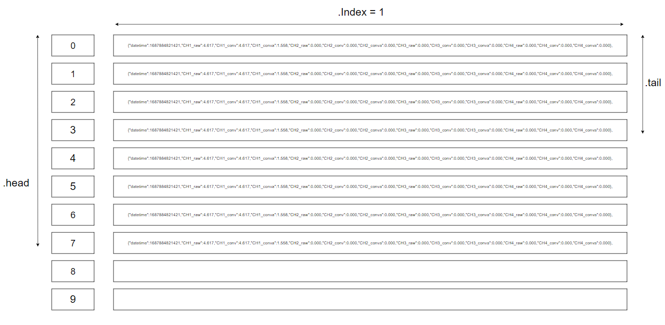
The depicted image demonstrates that when a JSON packet is fed into the input port of the write block, the matrix saves this packet by incrementing its header value. When the header value reaches 9, it's reset to 0, and the most recent packet is stored in the zero position. This cyclic behavior ensures efficient data storage and replacement.Considering this block design, it's crucial to implement reading of data before the header value reaches its maximum limit. When the read block is executed, it ensures the retrieval of all unread data as a unified entity, separated by commas.For a more comprehensive grasp of this process, I recommend trying out the provided demo. It will offer practical insight into the functioning of this buffer system.
Demo
Write data and read data in a single task
Demo1 file: esp32_cbuf_matrix_demo1.slx
Write data and read data in multiple task
Demo2 file: esp32_cbuf_matrix_demo2.slx
Demo 1 : Write data and read data in a single task
Description
This example serves as an educational tool to showcase the operational dynamics of circular buffer matrix blocks when executed within a singular task. The primary goal of this example is to facilitate a clear comprehension of the process of writing data into the block and subsequently reading data from it.
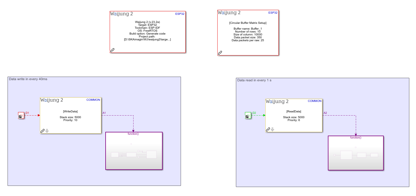
Full Model
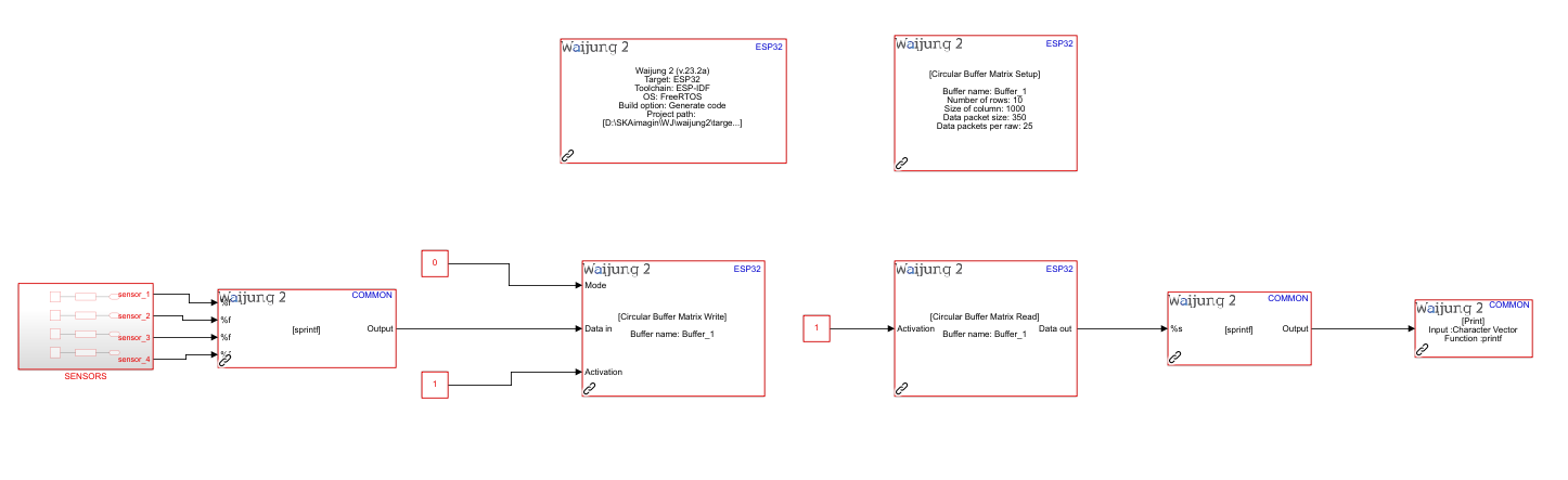
What should be happening?
Build the "demo1" file by compiling the provided demo file. Upon successful deployment of this file to the hardware, proceed to initiate the serial communication software for testing the aforementioned demo. In the software interface, choose the appropriate COM port to establish a connection for data monitoring.
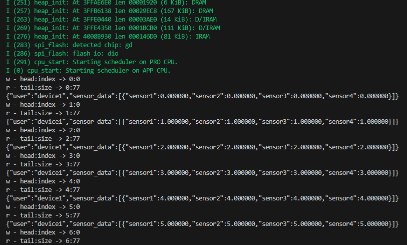
Referring to the image above, you'll observe a comprehensive depiction of the process. This image illustrates the seamless flow of sensor data being written into the matrix buffer and subsequently read from it, all within the confines of a single task execution. This visual representation highlights the inherent efficiency of circular buffer matrix blocks in managing data operations.By following these steps, you will gain valuable hands-on experience in comprehending the real-world functioning of the circular buffer matrix blocks, solidifying your understanding of data writing and reading processes within a cohesive task environment.
As evident from the image above, sensor data has been successfully written into the matrix buffer and subsequently read from it. The displayed information includes the write position (head) and the corresponding column index, providing a point of reference. Additionally, the read position (tail) along with the packet size is also indicated for your convenience.
Demo 2 : Write data and read data in a multiple task
Description
This scenario is similar to the 'demo1' setup. It involves the concurrent operation of both write and read blocks within multiple tasks, each operating at distinct sample times: 40ms for the write block and 1 second for the read block.
Full Model
What should be happening?
Build the "demo2" file by compiling the provided demo file. Upon successful deployment of this file to the hardware, proceed to initiate the serial communication software for testing the aforementioned demo. In the software interface, choose the appropriate COM port to establish a connection for data monitoring.
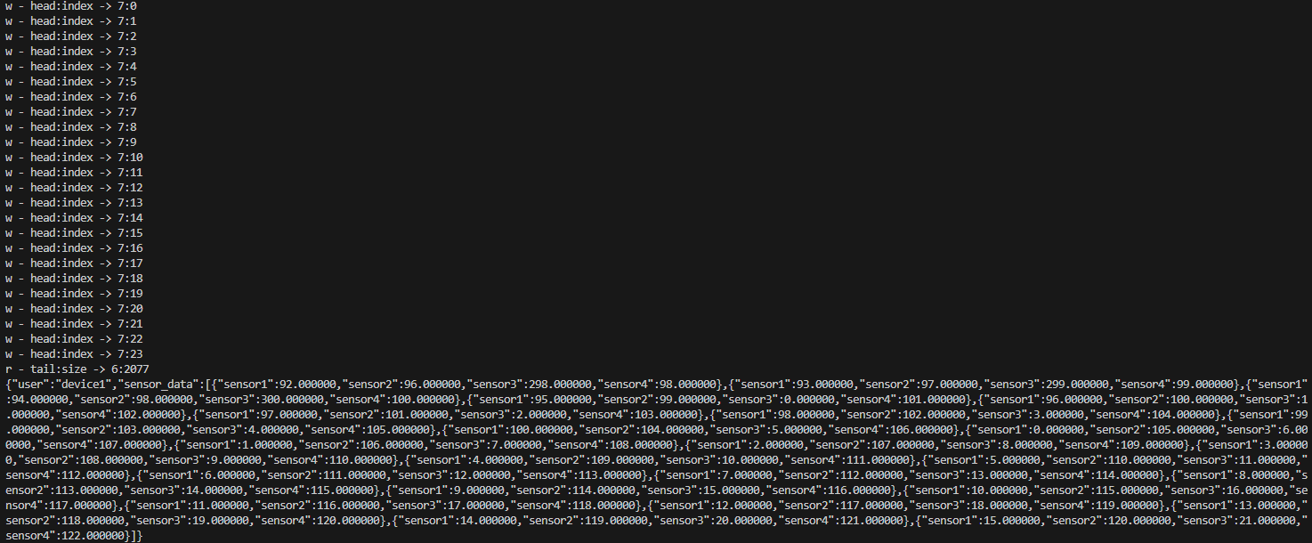
Given that the write block operates at a frequency of 40ms, it effectively writes 25 data points into the buffer every second. Consequently, within the span of 1 second, it accumulates and stores 25 JSON packets within each row of the buffer. On the other hand, the read block, scheduled at a 1-second interval, retrieves data. As evidenced by the serial print, this read operation extracts and displays 25 JSON packets, aligning with the write block's rate.