The “Developing a Stand-alone System” topic focuses on creating an integrated system that combines the control algorithm with a web application. This allows for real-time monitoring and control of the robot’s movements and behavior through a user-friendly web interface. The stand-alone system is designed to operate independently, ensuring that the robot can perform its tasks without the need for constant supervision or connection to development tools. This topic will cover the steps involved in integrating the components, testing the system’s functionality, and deploying it for practical use. It’s the culmination of the project, where all the individual parts come together to form a cohesive and autonomous robotic system.
Example Simulink Model: br_dth_remote.slx
Step 01: Start Simulink
Open MATLAB and start Simulink. Create a new model.
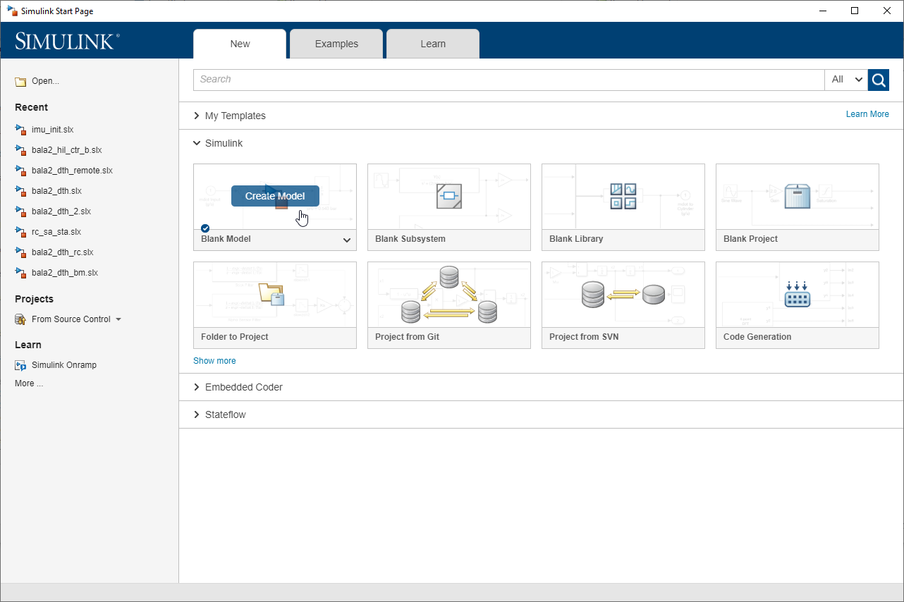
Figure 196: Create new Simulink model
Step 02: Add Waijung 2 Target Setup Block
From the Waijung2 blockset, find the Target setup block and add it to your model.
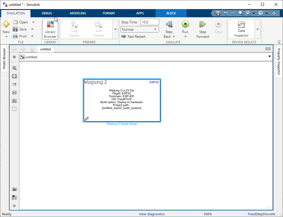
Figure 197: Add Waijung 2 Target Setup block to the model
Step 03: Configure Target Setup Block
Double-click on the Target setup block to open its configuration parameters. Set the build option to ‘Deploy to Hardware’. This mode allows you to run real-time simulations, which will be handy in later steps when reading the robot tilt angle.
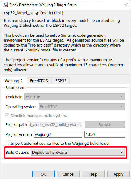
Figure 198: Select Deploy to Hardware as Build Option
Select FreeRTOS tab and change "Default xTaskCreate_stack depth" to 20480.
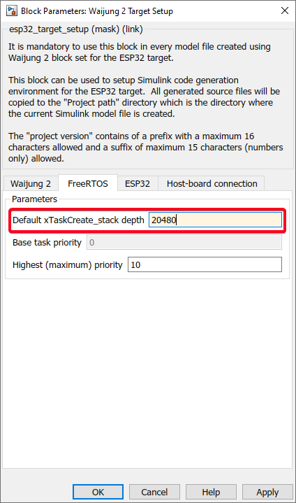
Figure 199: Increase Default xTaskCreate_stack depth to 20480
Select ESP32 tab and Select the COM port connected to M5Stack BALA2 FIRE. Also edit the Partition table and increase the factory partition Size to 2M.
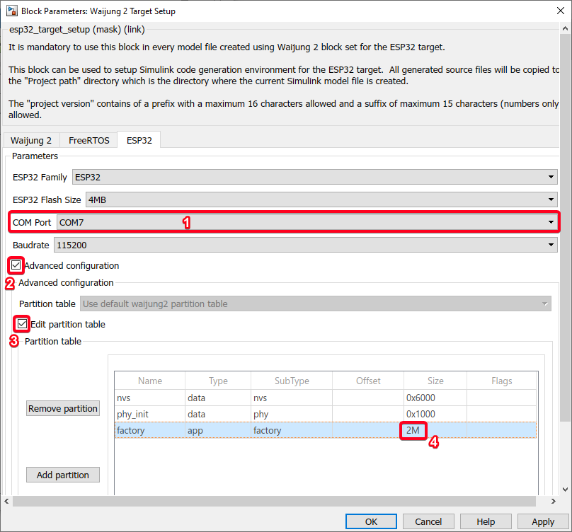
Figure 200: Select ESP32 COM port and edit partition table
Step 04: Add SD Setup block
From the Waijung2 blockset, find the SD Setup block and add it to your model. Configure it as following figure:
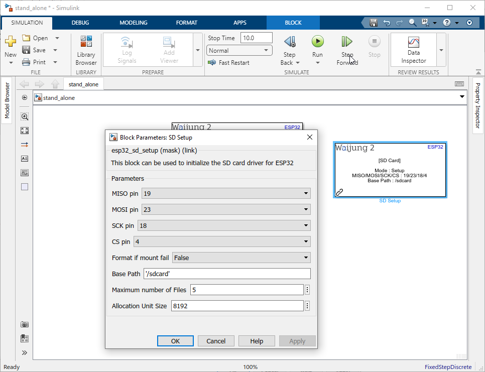
Figure 201: Configure SD Setup block for the SD card.
Step 05: Add Wifi Setup block
From the Waijung2 blockset, find the WIFI Setup block and add it to your model. Configure it as WIFI AP mode with ssid and password:
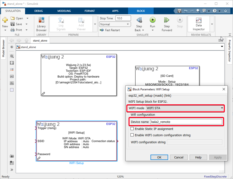
Figure 202: Add Wifi Setup block
Step 06: Add String Processing blocks and Step block
From the Waijung2 blockset, find the String Processing block and add two blocks to your model. Set Function to sprintf and insert Wifi SSID and Password in the Formal property. Also add a Step block to trigger the Wifi Setup block and use following configuration on the figure:
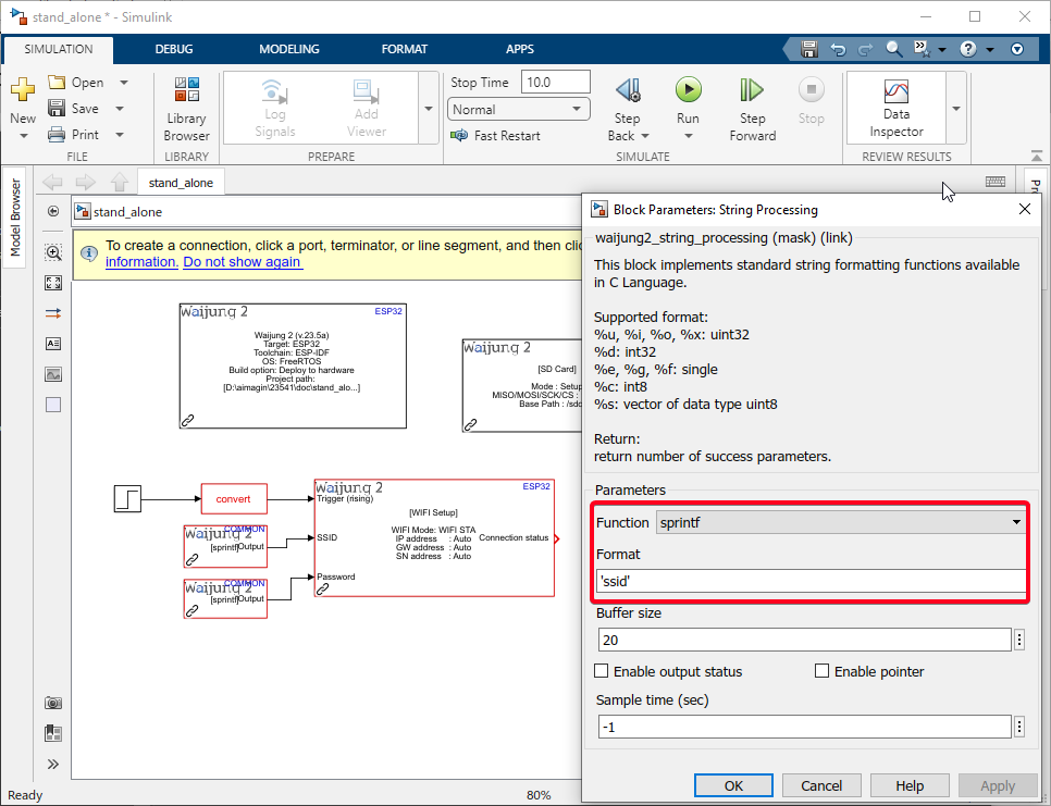
Figure 203: Insert SSID and Password
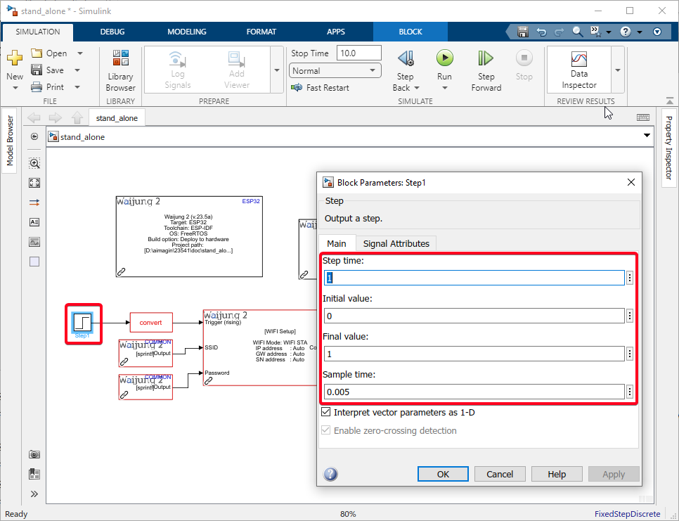
Figure 204: Create a trigger using Step block
Step 07: Add Enable Subsystem
From the Simulink blockset, find the Enable Subsystem block and add it to your model. Connect it to a status of Wifi Setup block through a comparison block. Compare to constant block will enable the subsystem when the value of wifi setup status equal to 0 (This represents a successful initialization of the Wifi connection without errors).
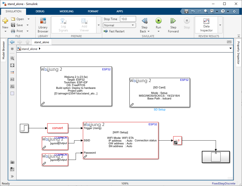
Figure 205: Add Enable Subsystem
Step 08: Add Aimagin Connect blocks
From the Waijung2 block set, find the Aimagin Connect Server block and Aimagin Connect Custom mode block add it to your model. Configure Aimagin Connect Custom mode block by adding the new mode name get_input.
Note: Enter the same mode name used in the init callback of the created web page.
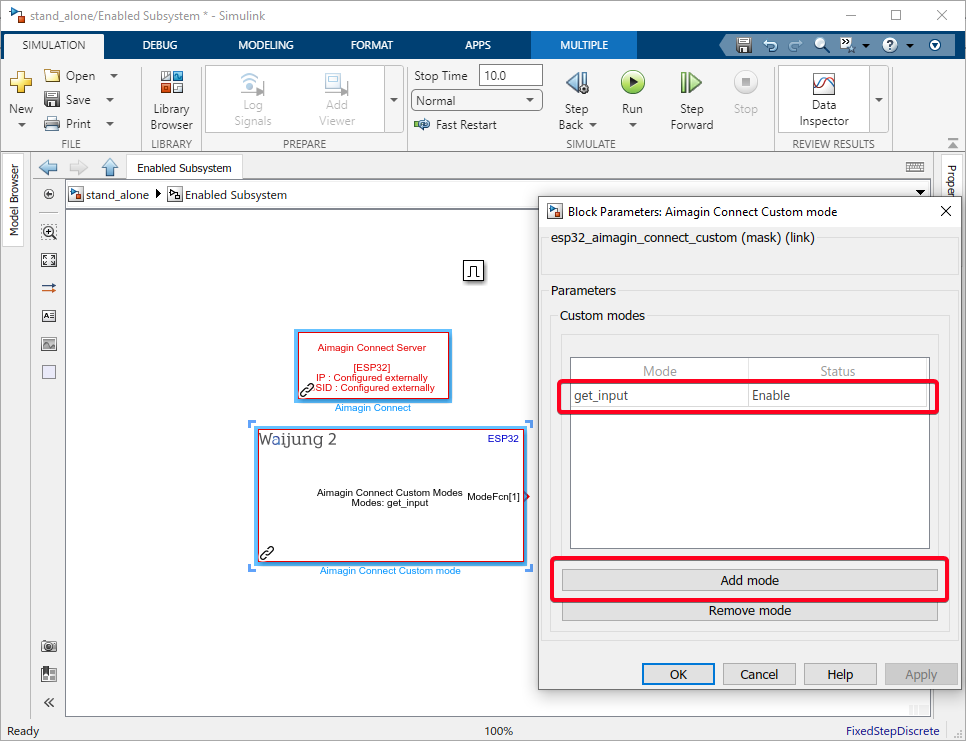
Figure 206: Add Aimagin Connect Server and Custom blocks
Step 09: Add Function-Call Subsystem
From the Waijung2 blockset, find the Function-Call Subsystem block and add it to your model.
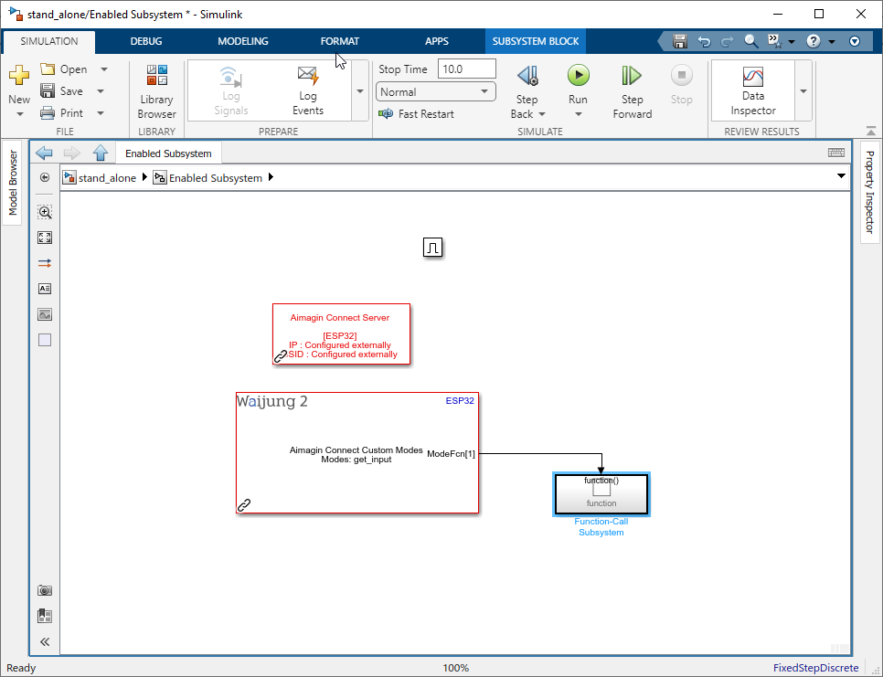
Figure 207: Add Function-Call Subsystem
Step 10: Add Aimagin Connect Read Request block
From the Waijung2 blockset, find the Aimagin Connect Read Request block and add it to your model. Use String Processing block with sscanf Configuration to extract the web page push button actions.
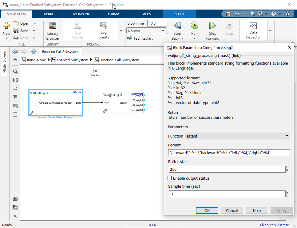
Figure 208: Read data from the web page inputs
Step 11: Include Movement Control Algorithm
Copy and paste the Movement Control Algorithm implemented on the Developing and Testing Movement Control Algorithm tutorial.
Add two more conditions to prevent the robot from moving when conflicting commands are given, such as pressing both the forward and backward buttons or the left and right buttons at the same time. This is important for devices that support multi-touch, where multiple buttons can be pressed simultaneously.
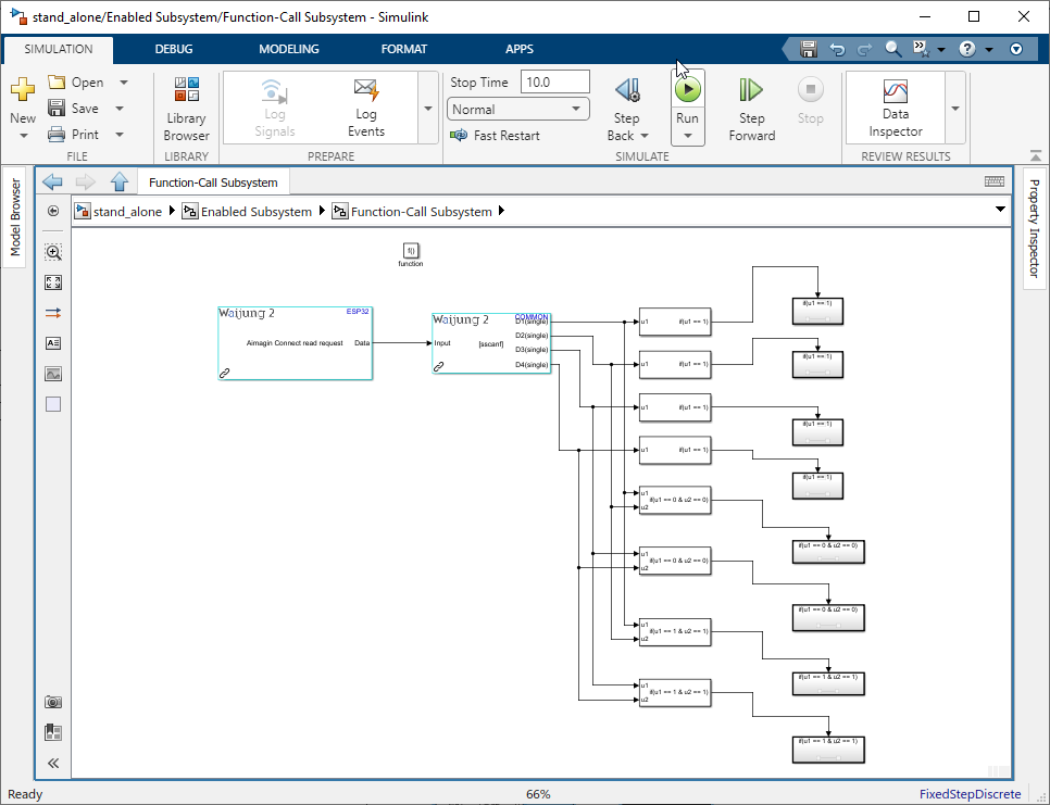
Figure 209: Copy the Movement control algorithm
Step 12: Add Aimagin Connect Send Response
From the Waijung2 blockset, find the Aimagin Connect Send Response block and add it to your model. Use the String Processing block with sprintf Function to send a response confirming the receipt of the push button values.
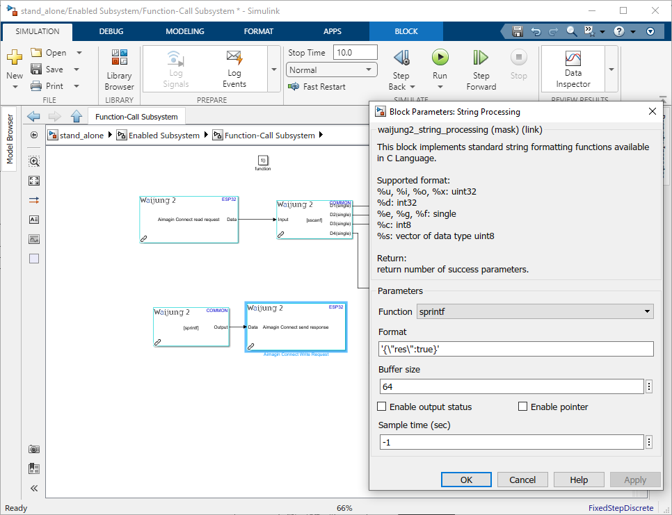
Figure 210: Sending response to confirm data received
Step 13: Add Balancing components
Copy and paste the Balancing components from the br_control_movement.slx.
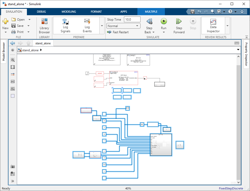
Figure 211: Copy the balancing components
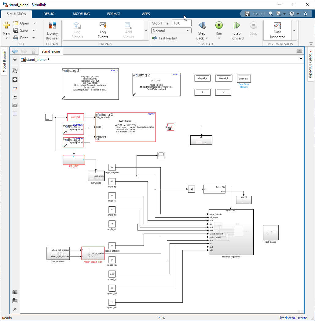
Figure 212: Stand alone model
Example Simulink Model:br_dth_remote.slx
Step 14: Open Embedded Coder
Select APPS from the toolstrip and Select Embedded Coder.
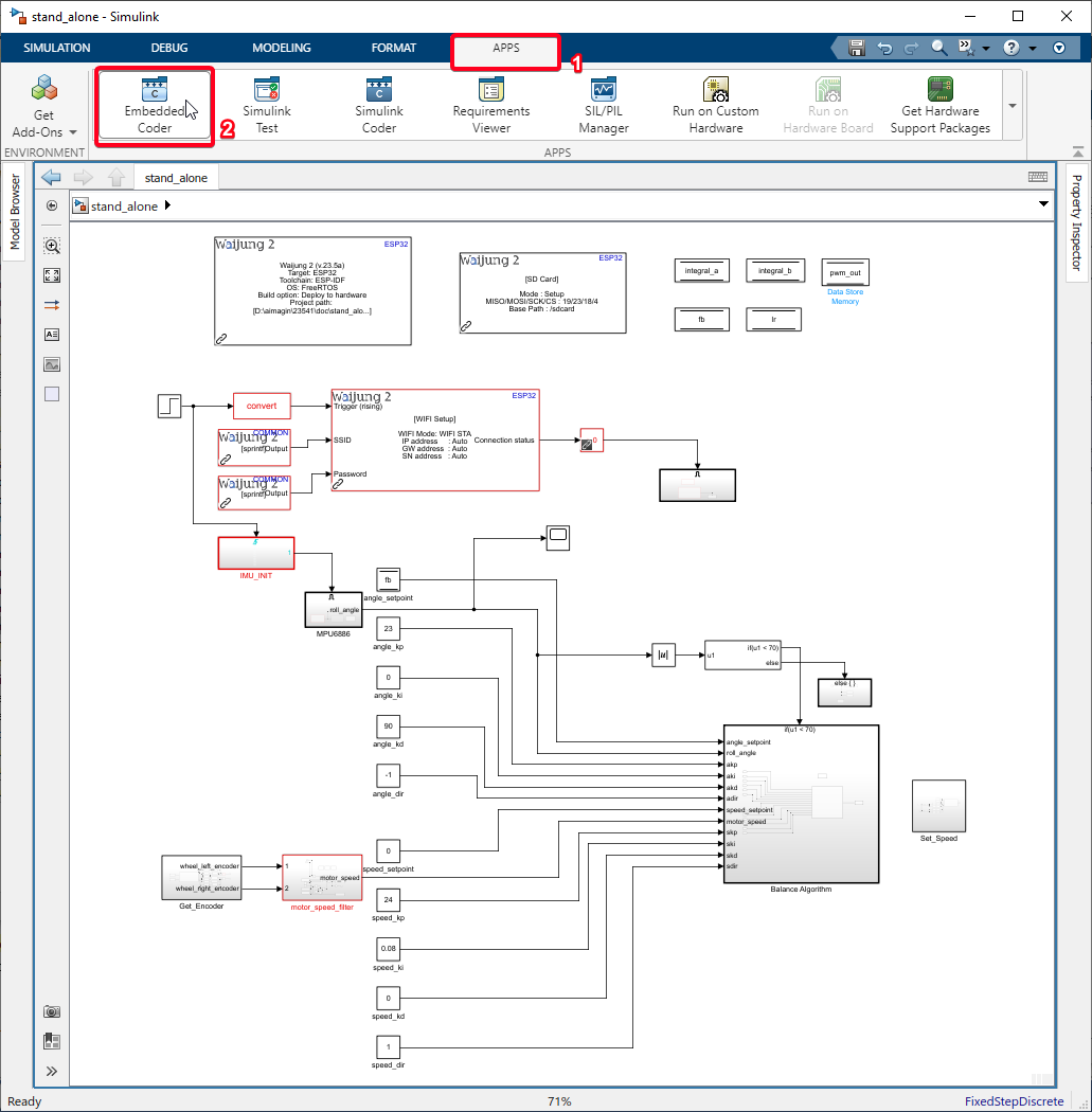
Figure 213: Open Embedded Coder
Step 15: Build the Simulink Model
Select the Build button to build the Simulink model to the balancing robot.
Note: Insert the SD Card to the balancing robot with the web app exported data before building the model.
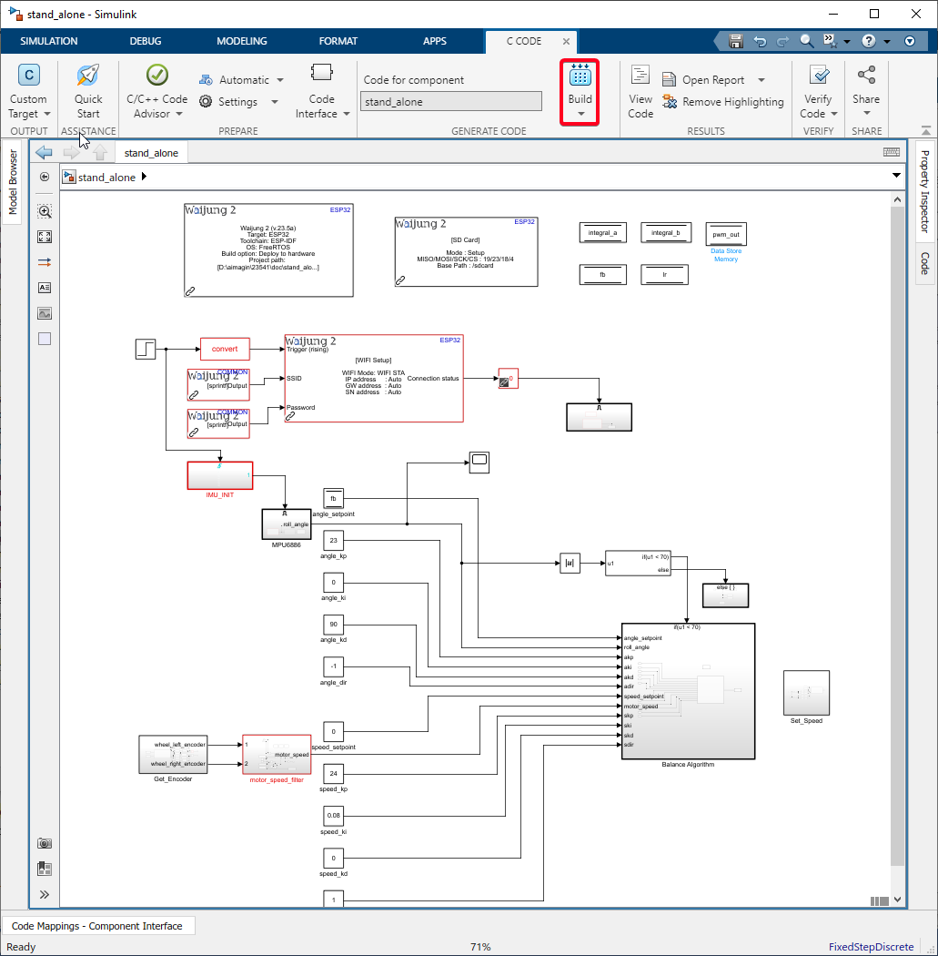
Figure 214: Build Model to Bala2 Robot
Step 16: Find the IP address
Find the IP Address of the Balancing robot by connecting to the COM port using a Serial Monitor(eg: Docklight,Putty).
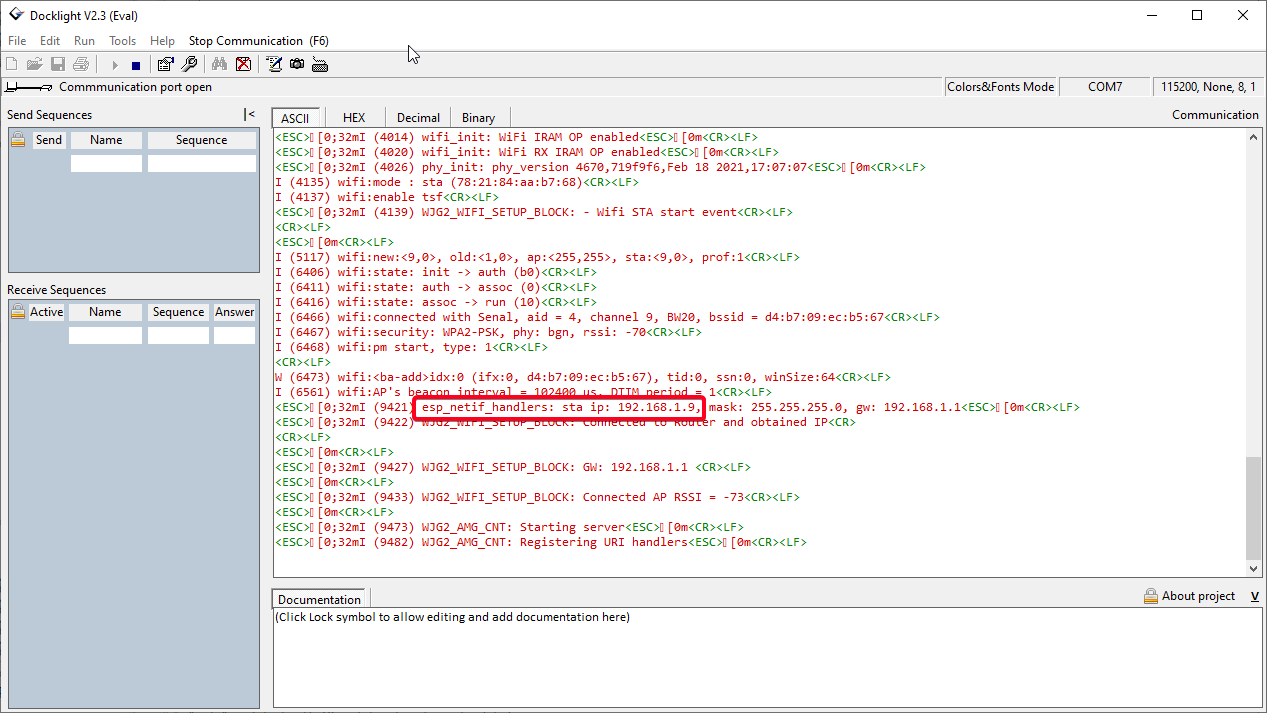
Figure 215: Find IP address
Step 17: Sign-in to Aimagin Analytics Account
Open a web browser and enter the IP address on the address bar. Sign in to the Aimagin Analytic account using SSID and password.
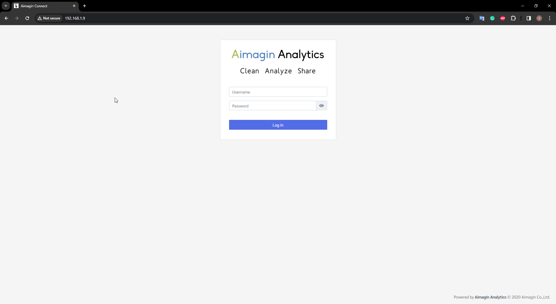
Figure 216: Enter IP address and sign in to Aimagin Analytics account
Step 18: Open Web App
Select the BALA2 in the web app.
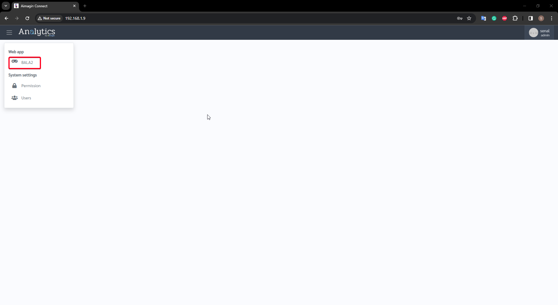
Figure 217: Open Web app
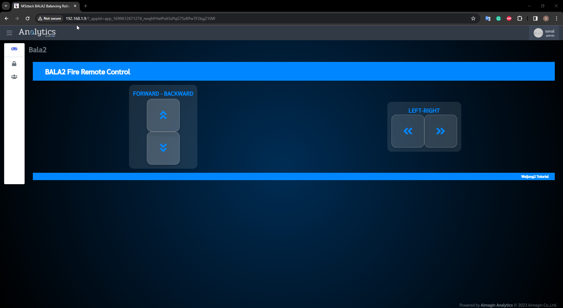
Figure 218: Web App
Self balancin robot remote control (Video)