Description
In this example M5StickC board is programmed to switch between two LED toggle patterns with the single push button using Simulink Stateflow with External mode. This will be the extension of Example 1.
Note: Before trying the tutorial please install the patch for digital input block.
Hands-on Simulink model
Step 1: Complete the steps up to Step 4 in previous example
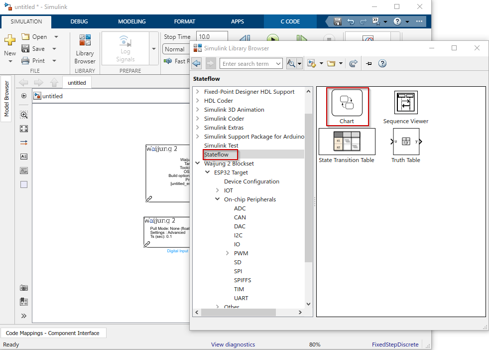
Step 2: Add Stateflow chart to the Simulink model
Step 3: Modify the Stateflow diagram as below
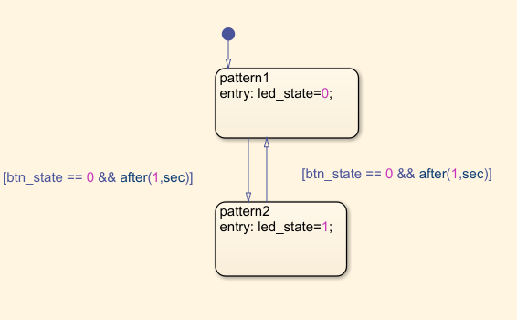
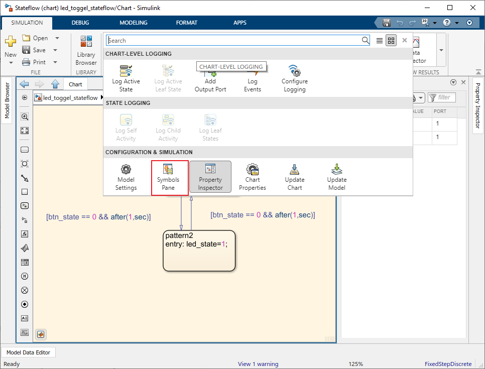
This Stateflow diagram has two states, pattern1 and pattern2 and the state transition will be occurred when the state of the push button (btn_state) is low and after 1 second elapsed. So it will be bouncing between two states when the push button is pressed. In each state there will be an output signal, led_state which will be used to switch the LED toggle patterns. In the pattern1 the led_state will be 0 and in the pattern2 it will be 1. Once the Stateflow diagram is modified as above, update the type of the state variables in the Symbols Pane. To open the Symbol Pane you can go to Simulation tab in Simulink and in the Prepare section Symbol Pane in the drop down menu
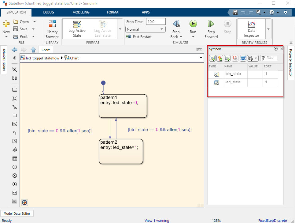
For this instance, btn_state will be input signal and the led_state will be output signal. Therefore
1.Set the type of btn_state as Input Data
2.Set the type of led_state as Output Data
Step 4: Add Switch, Constant and Pulse Generator blocks to the model and modify the mask parameters as below
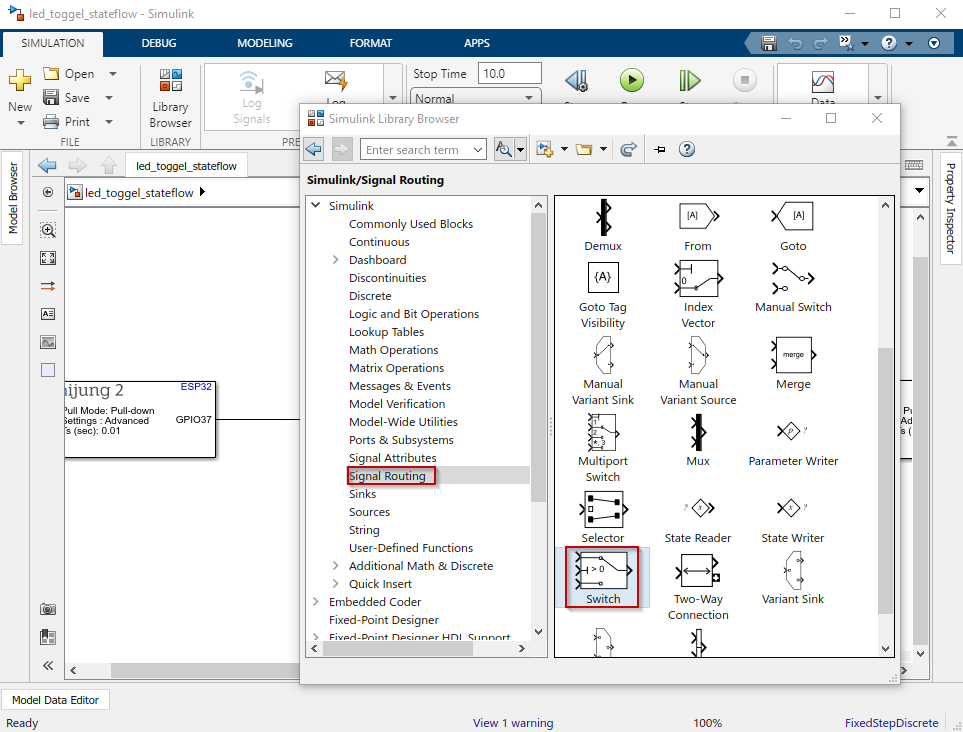
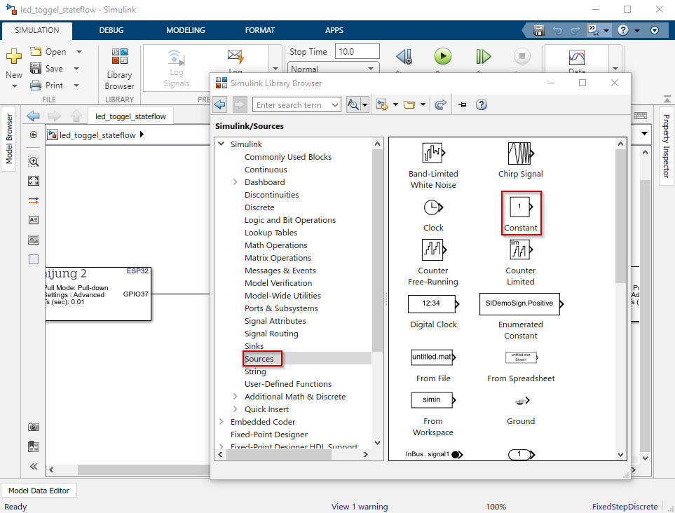
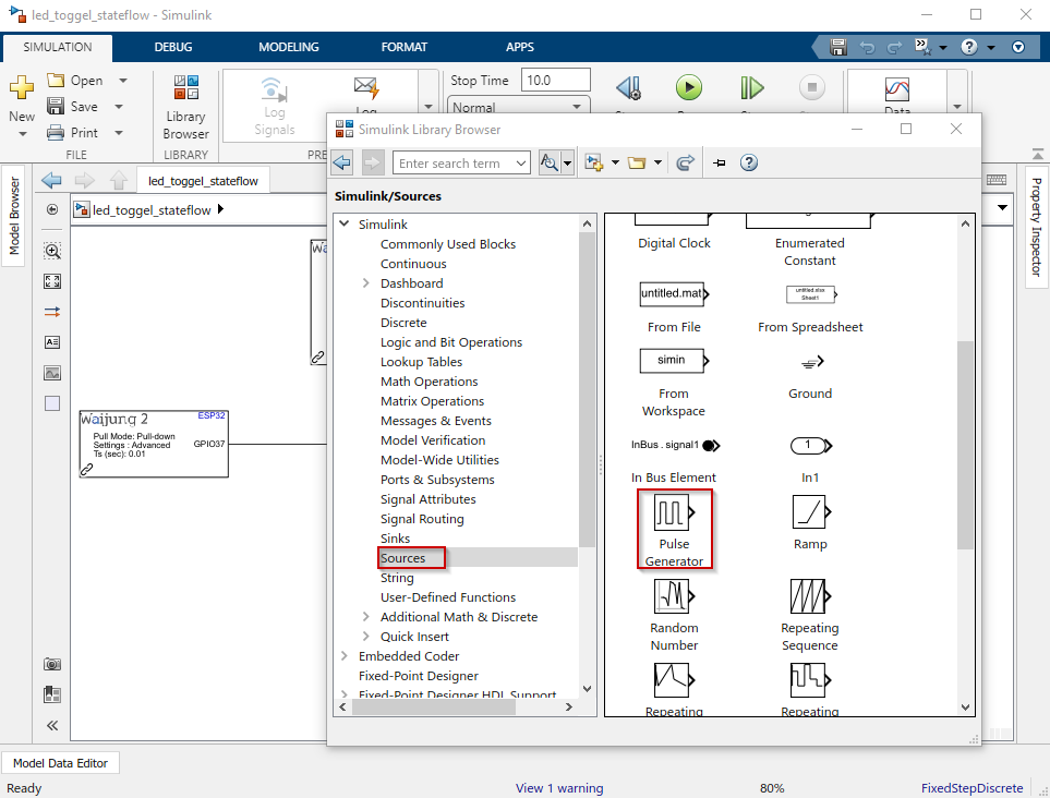
Modify Switch block parameters,
1.Set Threshold as 0
Modify Constant block parameters,
1.Set Constant value as 0
2.Set Sample time as -1
Modify Pulse Generator block parameters,
1.Set Pulse type as Sample based
2.Set Amplitude as 1
3.Set Period as 50
4.Set Pulse width as 25
5.Set Sample time as 0.01
Once the parameters are set connect each block as follow
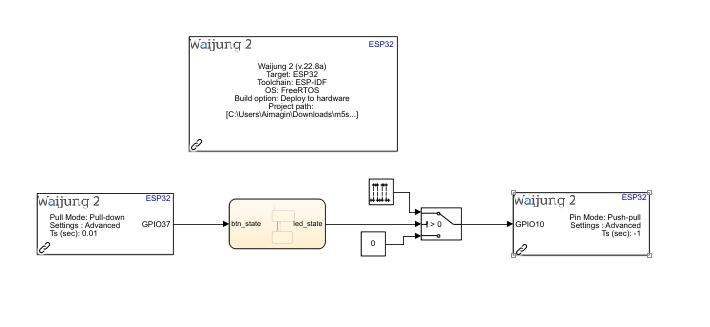
Step 5: Setting up the External mode
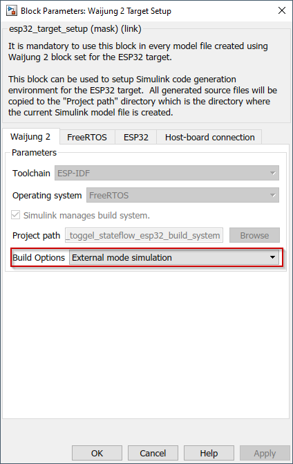
To enable the External mode in Waijung 2 go to Waijung 2 Target Setup block and open the block mask. Go to Waijung 2 tab and set the Build Options to External mode simulation.
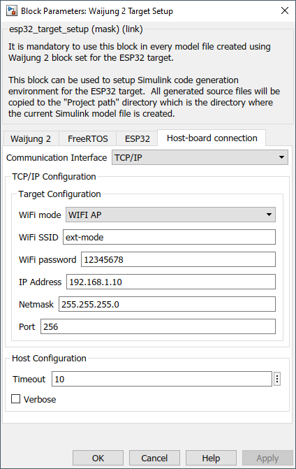
Then go to Host-board connection tab and set the configurations as below
1.set WiFi mode as WIFI AP
2.set WiFi SSID as ext-mode
3.set WiFi passward as 12345678
4.set IP Address as 192.168.1.10
5.set Netmask as 255.255.255.0
6.set Port as 256
Step 6: Save the Simulink model and Build
To build the Simulink model with External mode, go to Hardware tab in Simulink and click on Monitor & Tune drop down. Then click on Build for Monitoring.

Step 7: Once the model is uploaded to the ESP32, connect the computer to the ESP32 WiFi access point with the given WiFi SSID and Password in the Target Setup block mask. Then go to Hardware tab and open Control Panel. Click on Connect button to start the simulation
Once the simulation is started, press the push button to change the LED toggle pattern. The Stateflow diagram will simulate according to the button press.
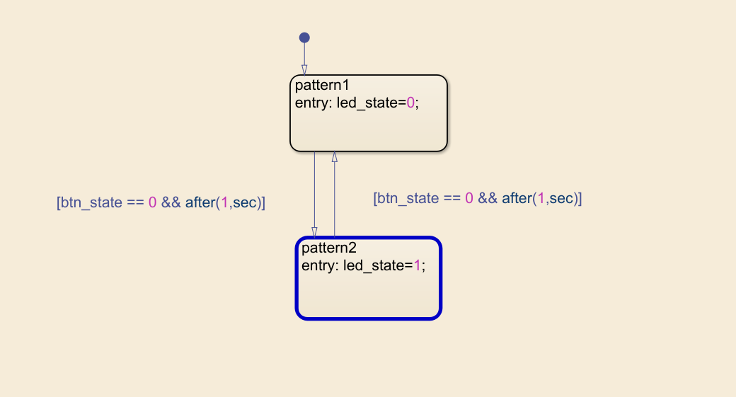
patteren1 : Solid LED HIGH signal
patteren2 : LED blinking pattern with the sample time of 500ms
Simulink model file: led_toggel_stateflow.slx