Description
This example demonstrates how to read gyroscope values from the onboard IMU MPU6886 via I2C communication.
Note: Before trying the tutorial please install the patch for digital input block.
Hands-on Simulink model
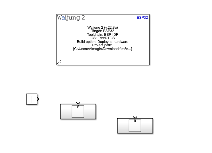
Step 1: Create new Simulink model and add Waijung 2 Target Setup, Step, Triggered Subsystem and Enabled Subsystem blocks to the model
Step 2: Add 14 I2C Master blocks to the Triggered Subsystem as below. This triggered subsystem is used to initialize the IMU
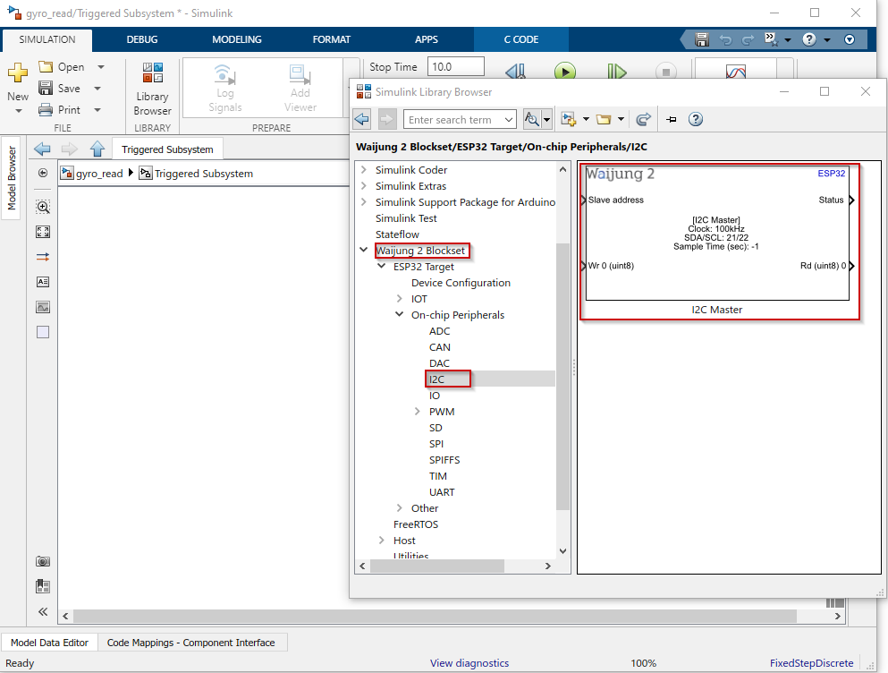
Step 3: Configure I2C Master blocks in the Triggered subsystem and add other required blocks
Configure mask parameters of I2C Master blocks,
1.Set Mode as Continuous
2.Set Clock speed as 100KHz
3.Set SDA pin as 21
4.Set SCL pin as 22
5.Set Bytes write count as 2
6.Set Bytes read count as 0
7.Set Sample time as -1
Add constant blocks with inherit sample time(-1) for each input port for each I2C Master block (except for the slave address port. One constant block is enough for all slave address port for each I2C Master block). Please refer the following table to identify byte values for each I2C Master block. For each block the Slave address will be 0x68.
I2C Master Block # |
1st write byte (register address) |
2nd write byte (register value) |
#1 |
0x6B |
0X00 |
#2 |
0x6B |
0x80 |
#3 |
0x6B |
0x01 |
#4 |
0x1C |
0x10 |
#5 |
0x1B |
0x18 |
#6 |
0x1A |
0x01 |
#7 |
0x19 |
0x01 |
#8 |
0x38 |
0x00 |
#9 |
0x1D |
0x00 |
#10 |
0x6A |
0x00 |
#11 |
0x23 |
0x00 |
#12 |
0x37 |
0x22 |
#13 |
0x38 |
0x01 |
#14 |
0x1B |
0x18 |
For more information about the sensor please refer the mpu6886_datasheet.
Add a OR gate block with 14 inputs to check the Status port value of each I2C Master block and add Compare To Constant block to compare the all of the status signals are 0 as below. Connect that signal to an output port.
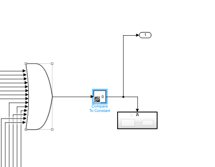
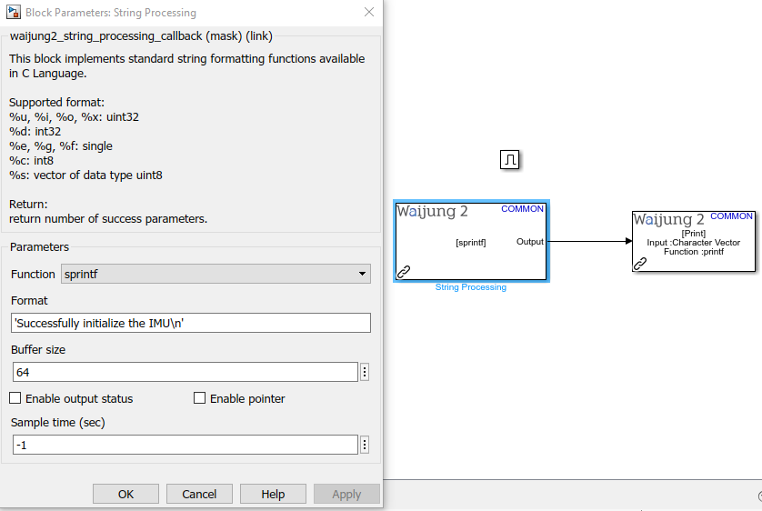
The additional Enabled Subsystem will be used to notify the user that the sensor is initialized successfully with a message through the serial interface using String Processing block and the Print block.
Step 4: Add I2C Master block and required blocks to read the sensor data in Enabled Subsystem
Add I2C Master block to the Enabled Subsystem and configure the mask parameters as below.
1.Set Mode as Continuous
2.Set Clock speed as 100KHz
3.Set SDA pin as 21
4.Set SCL pin as 22
5.Set Bytes write count as 1
6.Set Bytes read count as 6
7.Set Sample time as -1
For Input ports of I2C Master block, use Constant blocks with inherit sample time (-1) ,
1.Slave address: 0x68
2.Write byte0: 0x43
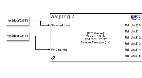
There will be 6 bytes read from the above registry. Each two bytes represent the gyroscope values through x,y and z axis of the IMU.
•Rd0: Most significant byte of X axis
•Rd1: Least significant byte of X axis
•Rd2: Most significant byte of Y axis
•Rd3: Least significant byte of Y axis
•Rd4: Most significant byte of Z axis
•Rd5: Least significant byte of Z axis
Each pair of bytes should be converted to a 16-bit value convert it to a physical value

The last Enabled Subsystem is used to print the values of the gyroscope via the serial interface
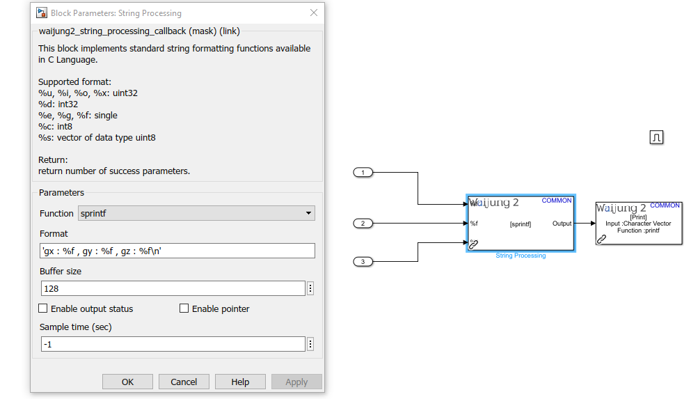
Step 5: Configure the Step block parameters and connect the main Triggered Subsystem and Enabled Subsystem as below
Set Sample time of the Step block to 0.2
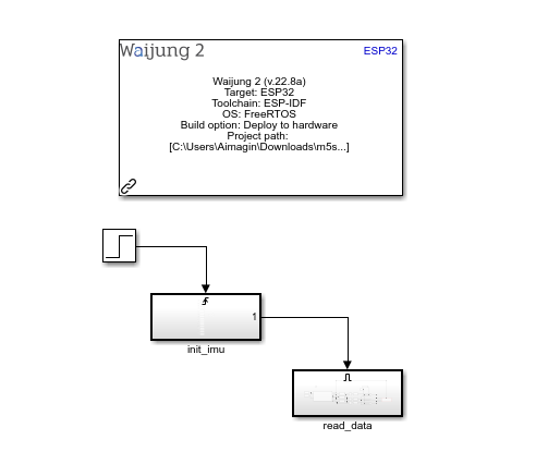
Step 6: Build the model to compile and upload to the ESP32
Step 7: Once the Simulink model is uploaded to the target, open the serial monitor to view the gyroscope values
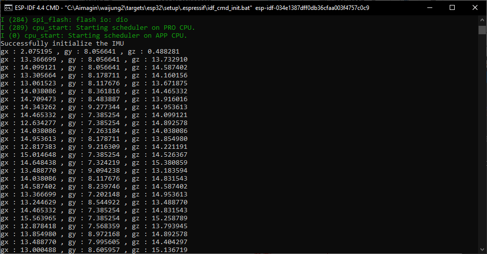
Simulink model file: gyro_read.slx