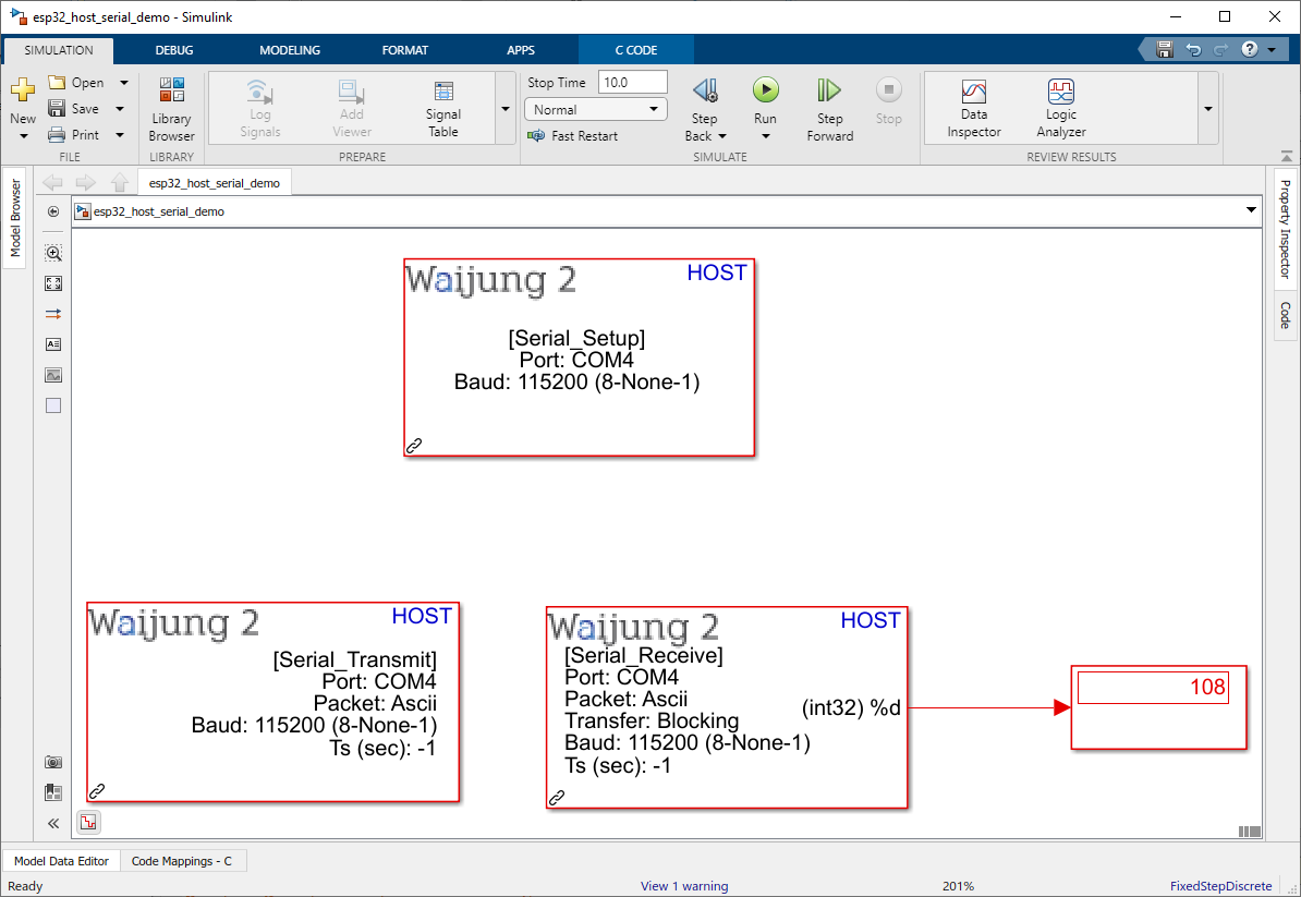
How do these blocks appear in a Simulink model?

What can be configured?
HOST SERIAL SETUP
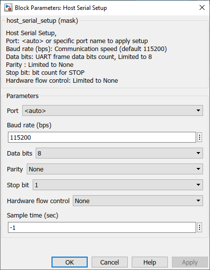
Configuration Parameter |
Selectable Option/Value |
Description |
Port |
auto--available ports |
Select COM port. |
Baud rate (bps) |
Communication speed configuration value, Example: 9600, 115200, or 1000000 |
Select baud rate. |
Data bits |
8 |
The block limit Data bit selection to 8. |
Parity |
None |
The block limit Parity bit selection to None. |
Stop bit |
1--1.5--2 |
Stop bit selection. |
Harware flow control |
None |
The block limit Hardware flow control to None. |
Sample time (sec) |
-1 (inherited) or specify |
Specify the sample time. |
HOST SERIAL Tx
Packet mode – ASCII / Binary / Binary Vector
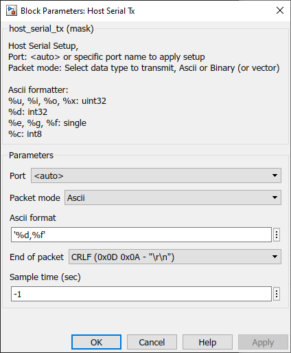
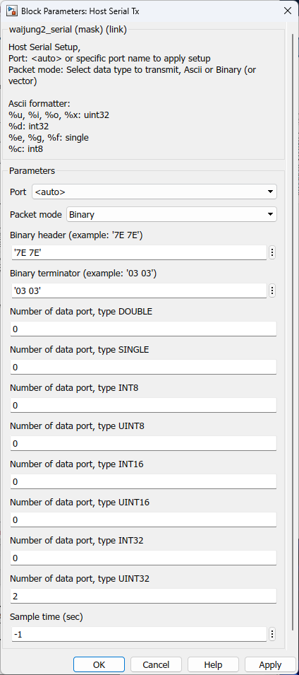
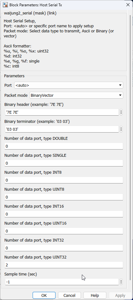
Configuration Parameter |
Selectable Option/Value |
Description |
Port |
auto--available ports |
Select COM port |
Packet mode |
Ascii--Binary--Binary Vector |
Ascii : This packet mode will transmit the packets that contain ASCII data (string), by specifying the sscanf format. The block will create the input port corresponding to the sscanf % format. For example: for the packet format "Value=%d", the input port of the block will be int32. Binary : This packet mode will transmit the packets that contain binary data, by specifying the Header, Data format, and Terminator of a packet to transmit. The block will not transmit the packet which contains an invalid Header or Terminator. Binary Vector : Same as Binary format, but the input port will be vector. |
ASCII format |
|
Scanf format specifier, start with %. Below is supported by the block. %u, %i, %d, %o, %x: sscanf input will be the type of uint32 %e, %g, %f : sscanf input will be the type of single %s: sscanf input will be the type of string. |
End of packet |
CR--LF--CRLF |
Terminator in ASCII mode is used to detect the end of the packet. The block will transmit ASCII with the terminator. |
Binary header (example: '7E 7E') |
Specify the Header pattern of the packet to transmit |
This header is used for packet synchronization. |
Binary terminator (example: '03 03') |
Specify the terminator pattern of the packet to transmit |
This terminator is used for packet validation. |
Number of data port, type DOUBLE |
Specify the number of data type double |
For packet mode: Binary - Number of input port type double BinaryVector - Port width of port type double |
Number of data port, type SINGLE |
Specify the number of data type single |
For packet mode: Binary - Number of input port type single BinaryVector - Port width of port type single |
Number of data port, type INT8 |
Specify the number of data type int8 |
For packet mode: Binary - Number of input port type int8 BinaryVector - Port width of port type int8 |
Number of data port, type UINT8 |
Specify the number of data type uint8 |
For packet mode: Binary - Number of input port type uint8 BinaryVector - Port width of port type uint8 |
Number of data port, type INT16 |
Specify the number of data type int16 |
For packet mode: Binary - Number of input port type int16 BinaryVector - Port width of port type int16 |
Number of data port, type UINT16 |
Specify the number of data type uint16 |
For packet mode: Binary - Number of input port type uint16 BinaryVector - Port width of port type uint16 |
Number of data port, type INT32 |
Specify the number of data type int32 |
For packet mode: Binary - Number of input port type int32 BinaryVector - Port width of port type int32 |
Number of data port, type UINT32 |
Specify the number of data type uint32 |
For packet mode: Binary - Number of input port type uint32 BinaryVector - Port width of port type uint32 |
Sample time (sec) |
-1 (inherited) or specify |
Specify the sample time. |
HOST SERIAL Rx
Packet mode – ASCII / Binary / Binary Vector
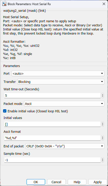
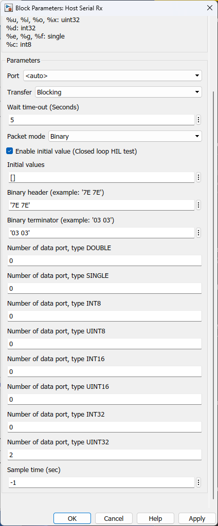
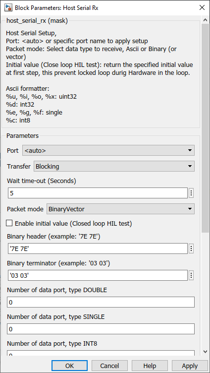
Configuration Parameter |
Selectable Option/Value |
Description |
Port |
auto--available ports |
Select COM port |
Transfer |
Blocking--Non-Blocking |
Select transfer mode |
Wait time-out (Seconds) |
number of seconds |
Enter the wait time-out in seconds |
Packet mode |
Ascii--Binary--Read Line |
Ascii : This packet mode will accept the packets that contain ASCII data (string), by specifying the sscanf format. The block will create the output port corresponding to the sscanf % format. For example: for the packet format "Value=%d", the output port of the block will be int32. If packet "Value=100" is received, the block will return 100 to the output port of the block. Binary : This packet mode will accept the packets that contain binary data, by specifying the Header, Data format, and Terminator of a packet to receive. The block will not accept the packet which contains an invalid Header or Terminator. Binary Vector : Same as Binary format, but the input port will be vector. |
Enable initial value (Close loop HIL test) |
Checked--Unchecked |
Enable or disable sending initial value, this prevents locked loop during Hardware in the loop. |
ASCII format |
|
Scanf format specifier, start with %. Below is supported by the block. %u, %i, %d, %o, %x: sscanf output will be the type of uint32 %e, %g, %f : sscanf output will be the type of single %s: sscanf output will be the type of string. |
End of packet |
CR--LF--CRLF |
Terminator in ASCII mode is used to detect the end of the packet. The block will continue to receive ASCII and store it in a buffer, and detect terminator at the same time. After finding and matching the terminator, the block will perform the sscanf function to extract the value in a packet. |
Binary header (example: '7E 7E') |
Specify the Header pattern of the packet to receive |
This header is used for packet synchronization, the block will continue searching for the header, once the header is matched then the next bytes will be data. |
Binary terminator (example: '03 03') |
Specify the terminator pattern of the packet to receive |
This terminator is used for packet validation, once the header is matched and all data types are received, the next bytes will be terminator. if the terminator is not matched, the block will reject the previous bytes (Header and data), and continue searching for a new packet starting with header again. |
Number of data port, type DOUBLE |
Specify the number of data type double |
For packet mode: Binary - Number of input port type double BinaryVector - Port width of port type double |
Number of data port, type SINGLE |
Specify the number of data type single |
For packet mode: Binary - Number of input port type single BinaryVector - Port width of port type single |
Number of data port, type INT8 |
Specify the number of data type int8 |
For packet mode: Binary - Number of input port type int8 BinaryVector - Port width of port type int8 |
Number of data port, type UINT8 |
Specify the number of data type uint8 |
For packet mode: Binary - Number of input port type uint8 BinaryVector - Port width of port type uint8 |
Number of data port, type INT16 |
Specify the number of data type int16 |
For packet mode: Binary - Number of input port type int16 BinaryVector - Port width of port type int16 |
Number of data port, type UINT16 |
Specify the number of data type uint16 |
For packet mode: Binary - Number of input port type uint16 BinaryVector - Port width of port type uint16 |
Number of data port, type INT32 |
Specify the number of data type int32 |
For packet mode: Binary - Number of input port type int32 BinaryVector - Port width of port type int32 |
Number of data port, type UINT32 |
Specify the number of data type uint32 |
For packet mode: Binary - Number of input port type uint32 BinaryVector - Port width of port type uint32 |
Sample time (sec) |
-1 (inherited) or specify |
Specify the sample time. |
When to use these blocks?
1.HOST SERIAL SETUP - The block must be placed into a Simulink model to enable/ configure the selected COM port when the simulation needs to send or receive data from an external device using the Serial protocol.
2.HOST SERIAL TX - Use this block to transmit data from the COM port when a simulation needs communication between the Simulink and a device via Serial protocol.
3.HOST SERIAL RX - Use this block to receive data from the COM port when a simulation needs communication between the Simulink and a device via Serial protocol.
How do these blocks work?
HOST SERIAL SETUP
The following overview describes how to establish communication between a Simulink simulation and other devices connected through a COM port using the functions and data types.
1.Setting Communication Parameters - Setting baud rate, data bits, stop bits, etc.
2.Setup HOST SERIAL TX/HOST SERIAL RX according to the application.
3.Run the Simulink Simulation.
HOST SERIAL TX
The block will transmit data from the selected COM port depending on the configurations selected by the user.
HOST SERIAL RX
The block will receive data from the selected COM port buffer and process the packet depending on the configurations selected by the user.
Demo
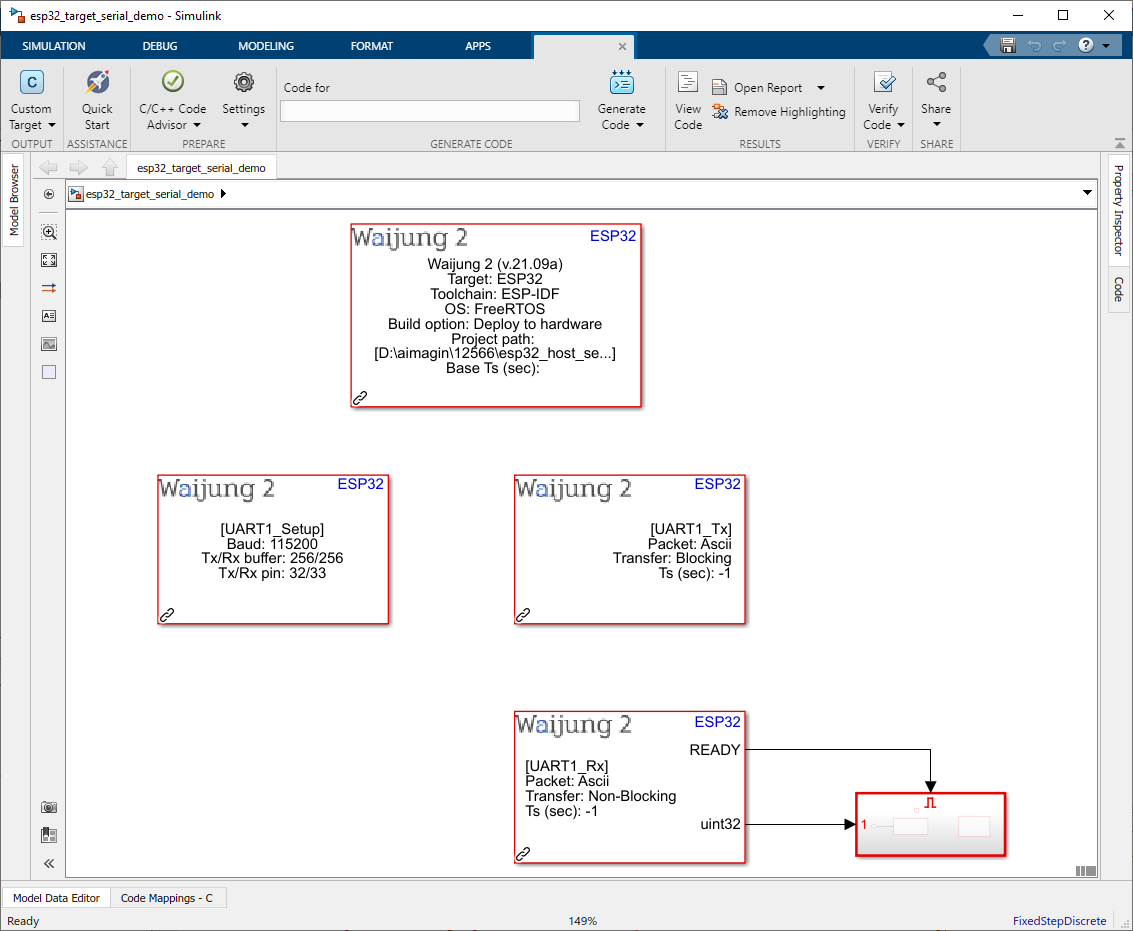
Target Demo file : esp32_target_serial_demo.slx
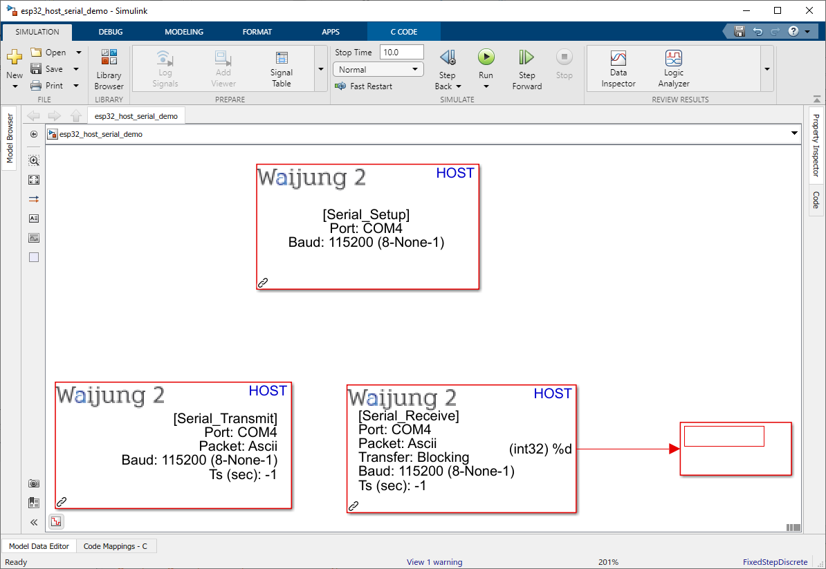
Host Demo file : esp32_host_serial_demo.slx
Description
The Host Serial blocks are capable of running simulations on Mathworks Simulink.
This demo shows the communication between the host pc and the target ESP32 using Host serial blocks. The user can send the string data (commands) to control or quarry data from ESP32 via COM port.
Hardware Setup
1.ESP32 module
2.USB to UART converter
3.Host PC (Simulink)
Connect ESP32 UART RX & TX pin with USB to UART converter UART TX & RX pins.
For the Host Serial blocks, select the COM port of the USB to UART converter.
After the Hardware setup is completed,
1.Flash target demo file to the ESP32
2.Run Simulink simulation on host demo file.
What should be happening?
In order to check Host Serial send(Tx)
Command - LED=1 will be sent to the ESP32 from Host Serial Tx during simulation,
Result - The GPIO2 will be HIGH
In order to check Host Serial send(Rx)
Command - Value=108 will be sent to the Host Serial Rx from ESP32 during simulation,
Result - The Display block will display 108
