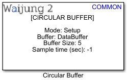
How this block appears in a Simulink model?
What can be configured?
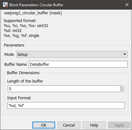
Mode: Setup
Configuration Parameter |
Selectable Option/Value |
Description |
Mode |
Setup--Write--Read |
Select the operation mode |
Buffer Name |
|
Allocate a name for the circular buffer |
Length of the buffer |
|
Number of data set rows to be held in the buffer at any given moment/time |
Input Format |
|
Data types of each data in a dataset row |
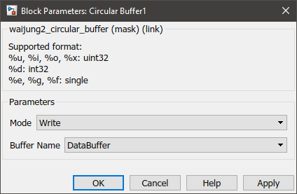
Mode: Write
Configuration Parameter |
Selectable Option/Value |
Description |
Mode |
Setup--Write--Read |
Select the operation mode |
Buffer Name |
|
Select the buffer name specified in Setup blocks |
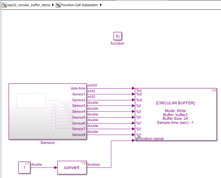
INPUT/ OUTPUT Port
Port Name |
Port Type |
Date Type |
Description |
activation |
Scalar |
boolean |
The block only works when the port receives a logic true |
Mode: Read
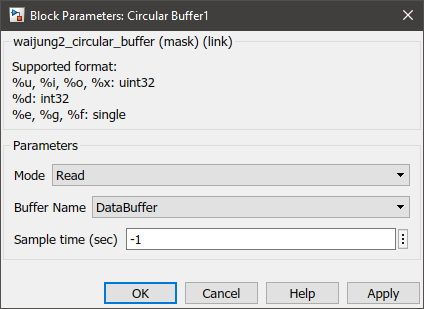
Configuration Parameter |
Selectable Option/Value |
Description |
Mode |
Setup--Write--Read |
Select the operation mode |
Buffer Name |
|
Select the buffer name specified in Setup blocks |
Sample time |
-1 (inherited) or specify |
Specify the sample time |
INPUT/ OUTPUT Port
Port Name |
Port Type |
Date Type |
Description |
activation |
Scalar |
boolean |
The block only works when the port receives a logic true |
When to use this block?
This block can be used to temporarily hold data to ensure no data loss when saving the data, due to a blocking process. The block implements the popular concept of Circular buffer_block found in Computer Science which uses a FIFO (first in, first out) logic.
How does this block work?
The block can be configured to function in three different modes,
•Setup: When selected, the block would initialize the circular buffers.
•Write: This mode is used when writing data to the circular buffers.
•Read: This mode is used when reading data from the circular buffers.
The number of data types the user specifies in the Input Format parameter is the number of circular buffers which the block would create. All of these circular buffers will have common head and tail index trackers. Length of the buffer parameter specifies the number of indexes for each circular buffer. The circular buffer block will only work when the activation signal input port is connected to the Boolean true signal.
Demo
Prerequisites
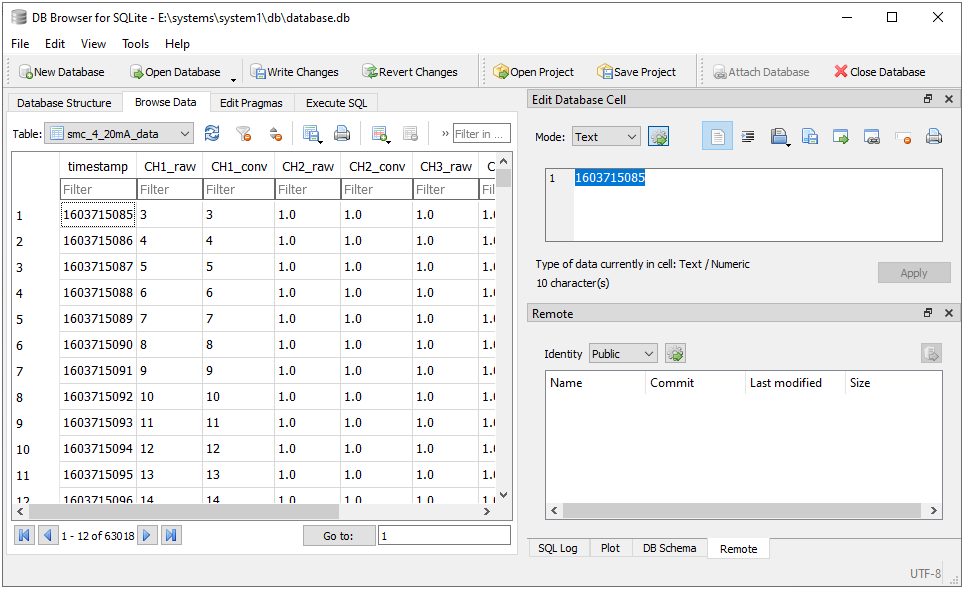
Create a database in the SD card using an Database browser. The following query can be used.
CREATE TABLE "smc_4_20mA_data" (
"timestamp" INTEGER,
"CH1_raw" TEXT,
"CH1_conv" TEXT,
"CH2_raw" TEXT,
"CH2_conv" TEXT,
"CH3_raw" TEXT,
"CH3_conv" TEXT,
"CH4_raw" TEXT,
"CH4_conv" TEXT
);
Demo file : esp32_circular_buffer_demo.slx
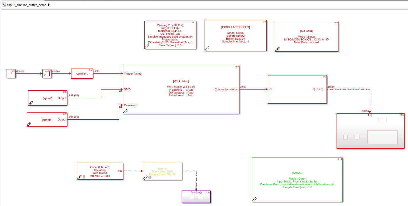
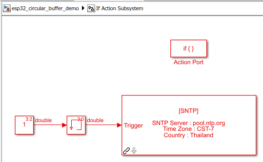
Description
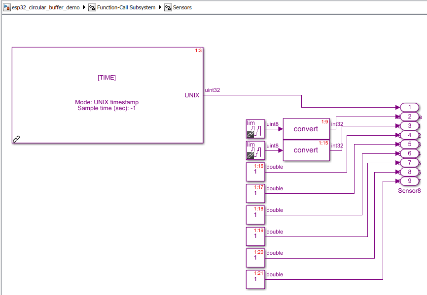
This demo shows a simple use case scenario for the circular buffer block. In this example data of 8 sensors (not actual sensors. Matlab Simulink blocks were used to mimic sensors) along with the UNIX timestamp needs to be inserted to the database. Inserting large amounts of data to a database could be a blocking process. Thus to ensure sensor readings are recorded every 1 second a circular buffer is used to hold the sensor data as an intermediate before writing to the database using the SQLite block.
Change the following configuration parameters in the model file.
In the WIFI block
•SSID: Any WiFi SSID with internet access
•Password: Password of the selected WiFi SSID
In the SQLite NonRetrieveData
•Database Path: Path to the database created in perquisites.
Hardware Setup
1.ESP32 module with SD card reader
2.WiFi connection with internet access
What should be happening?
When running the user could monitor INSERT commands to the database using a serial monitor. After a while the user could connect the SD card to a PC and check the sensor readings using a Database browser.