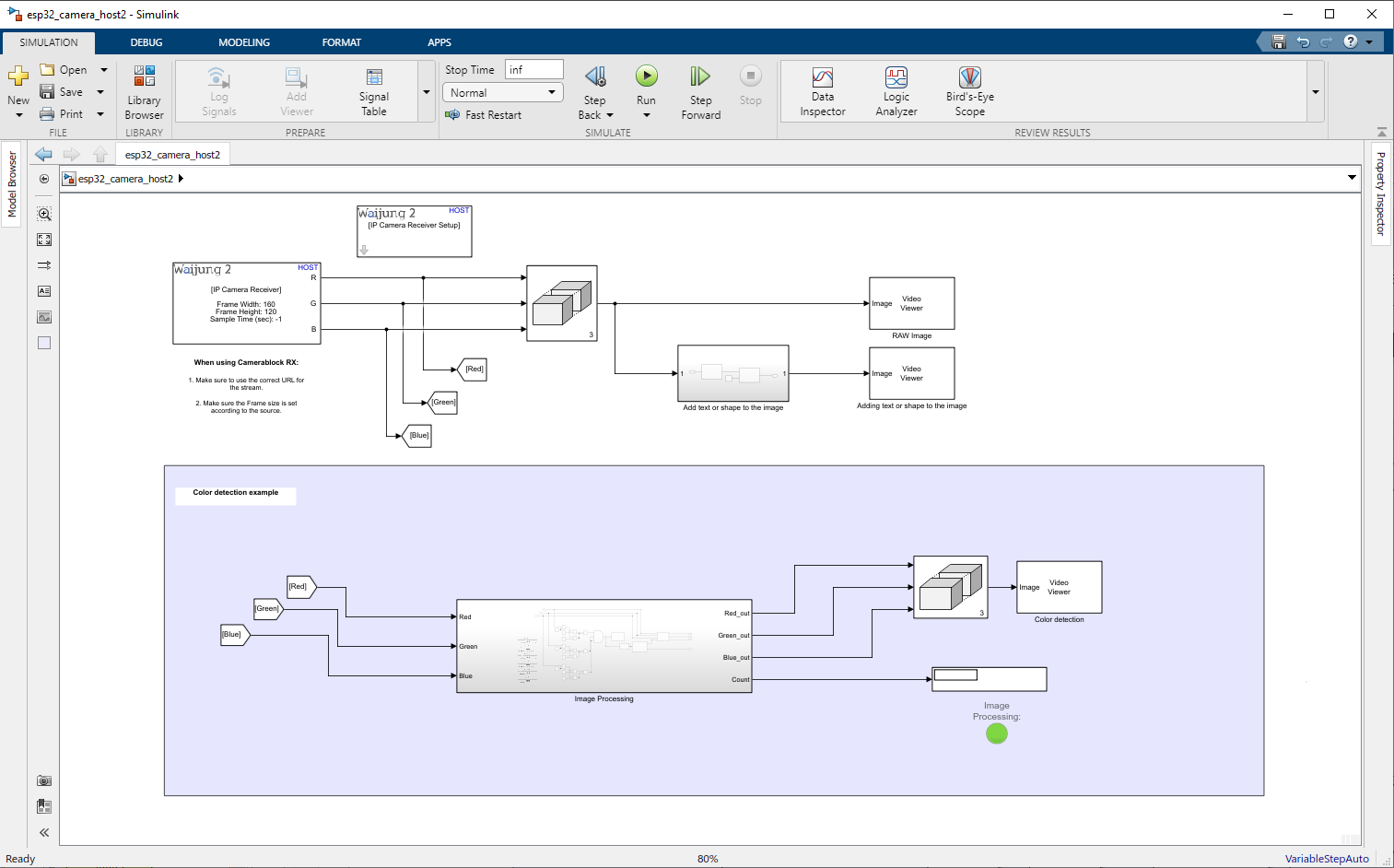
In this example, we focus on doing image processing and color detection for the camera feed received from the esp32-cam board. If you haven’t followed up on the previous example on how to get the video to Simulink, please follow that. : Simulink Acquire ESP32 IP Camera
Note: This example required "Computer Vision Toolbox"
In this example, we are mainly focusing on these topics.
1.Adding text & marker/shape to the image
2.Color detection
a.Control Simulink lamp with the color detection
b.Draw a bounding box around the detected area.
Adding text & shape to the image
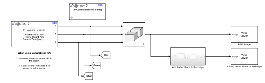
In this section, we use these blocks.
“IP Camera Receiver Setup”, “IP Camera Receiver”, “Matrix Concatenate”, “Video Viewer”, “Insert Text”, “Constant”, “Draw Shapes”
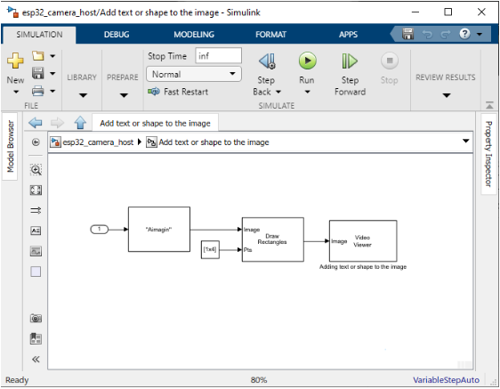
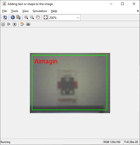
Outside the sub-section, it will give you the raw image from the camera. Inside the sub-section, it has a very simple example to show how to use the “Insert Text” & “Draw Shapes” blocks with the image.
The “Insert Text” block has these parameters in the mask:
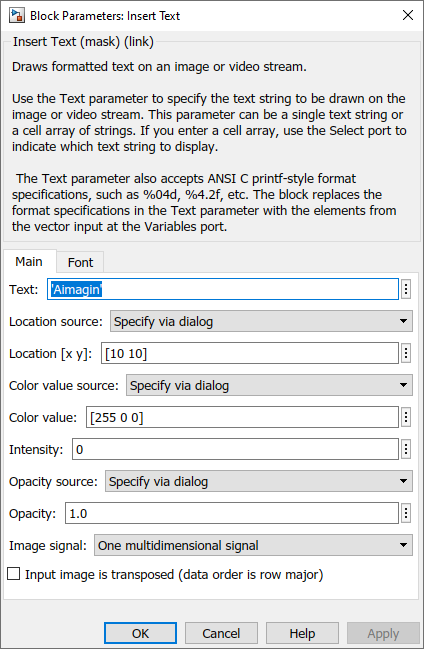
Text: text that needs to be added to the image
Location source: The user can set it via Input port as well. Then the x and y coordinates of the text location need to be added to the input port. To make it easier I use the default.
Location: Location where the text going to be in the image
Color value source: Can be changed to input port
Color value: RGB value needs to be given
Intensity: Color intensity
Opacity source: Can be changed to input port
Opacity: opacity value
Image signal: Can be set to separate color signals. Then RGB will be out separately.
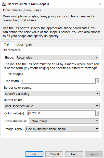
“Draw Shapes” block has these parameters in the mask:
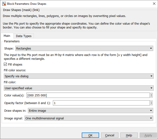
Shape: Rectangles/ Lines/ Polygons/ Circles. Select one from shapes.
Fill shapes: Tick if you need to fill out the shape.
Other parameters are related to the color of the shape.
Make sure to input the correct Shape coordinates for the block.
Please refer to this document for more details:
https://in.mathworks.com/help/vision/ug/draw-shapes-and-lines.html
From the video view block, this result can be obtained.
Color detection
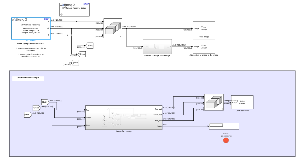
The highlighted area is the area for detecting the color from the image and processing the image. Each block and its process will be listed below.
Image processing subsystem has the following blocks
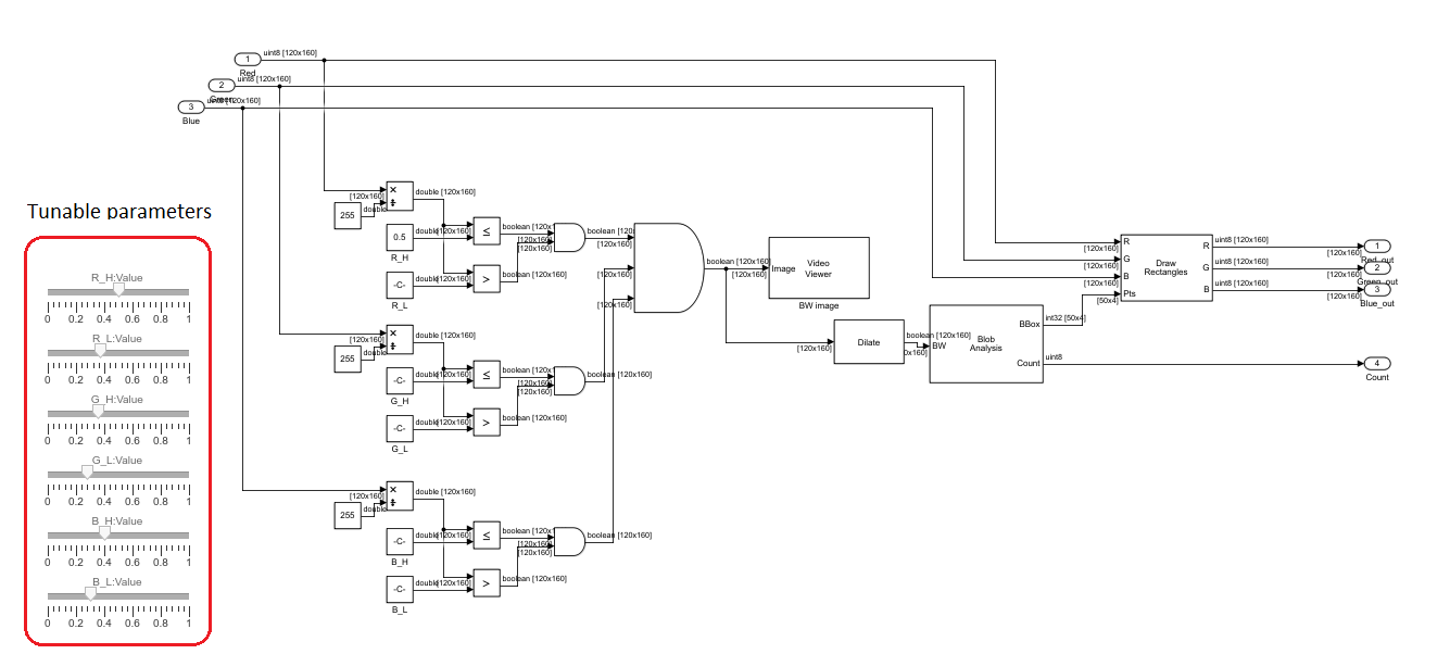
First, it will convert RGB image to BW image using filter sliders. Sliders will help to tune the filter out RGB values. BW image will go through with the morphological operation and be processed with the blob analysis block.
Control Simulink lamp with the color detection
This can be done with different techniques. In this document, let's discuss how to use the Blob Analysis block to use with the lamp
Trigger lamp using Blob Analysis block:
Use the BW image out from the MatLab function block for this. Do the morphological image processing to smooth out the noises of the image and connect the image to the “Blob Analysis” block. Blob analysis mask is shown by the following images. For more details on this block, please refer to this document: https://in.mathworks.com/help/vision/ref/blobanalysis.html
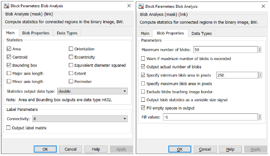
Here I unchecked "warn if the maximum number of blobs is exceeded" to prevent any warnings. Enabled "output actual number of blobs" to count the detections. Enabled the "specify minimum blob area in pixels" to remove small noises detected from the camera.
For these settings, there should be 4 outputs. We are using BBox and count in this example.
BBox: This port will output boundary box coordinates. We can connect this directly to the pts port of the “Draw Shapes” block.
Count: Count will output the number of blob counts detected from the image. I used a display block to show how many blobs the program detects from the video. Similarly, I used the same signal to light up the Simulink lamp.
How to use Simulink lamp in a program:
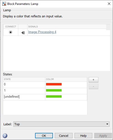
Open the lamp mask in the example. Then click the specific wire that takes the signal.
For example, click the wire that connects “blob analysis”(count port) with the “display” block.
Then it will be added to the mask. Select the correct signal and add states as defined. The picture below shows the configuration of the lamp mask.
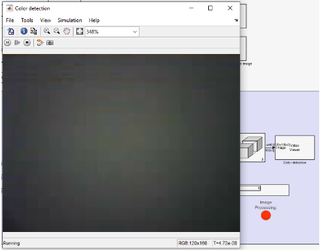
Results
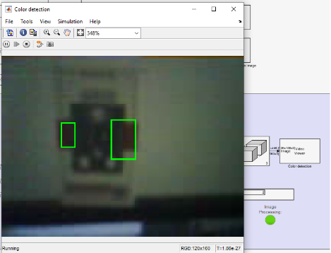
When the video detects the color, lamp will turn green. If it cannot detect the color it will turn to red.
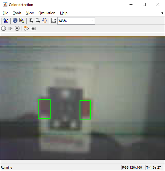
Draw a bounding box around the detected area
To draw a bounding box, the “Draw Shapes” block can be used. Coordinates are given by the “blob analysis” block. "Draw shapes" block needs an image input. For this, we use a raw image from the camera and draw on top of it.
Draw shape block mask is as follows.
Result:
Please find the example files from here: