In this project, we’re going to create a webserver to stream video to the Simulink host.
Required hardware:
•ESP32 board with a camera(Using ESP32-cam board for the example)
•USB to TTL converter (To upload code)
•5 female to female pin headers (To connect TTL converter to the board)
•Power source if needed.
Additional requirements
•Computer Vision Toolbox for Simulink
How to use Waijung camera block
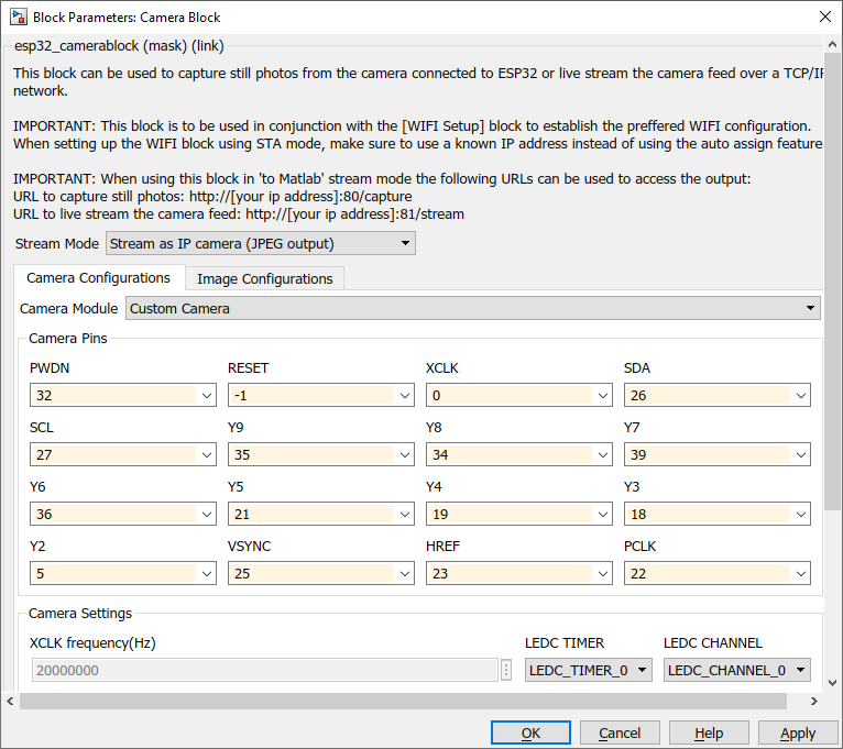
Select Stream Mode to "Stream as IP camera (JPEG output)" and then select the Camera Module. If the user cannot find the Camera Module select Custom Camera and enter the pins correctly. Pin configuration can be also found in the user manual of the board.
More settings for the video or image settings
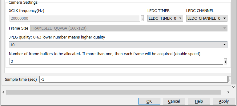
Note: When the video resolution/quality is increased, lag will be increased simultaneously.
This block required a WIFI setup block first. Wifi can be configured AP mode or STA mode. Both of these modes can be used with the camera block. For a beginner, I would suggest using AP mode which is easier to configure the settings.
AP mode
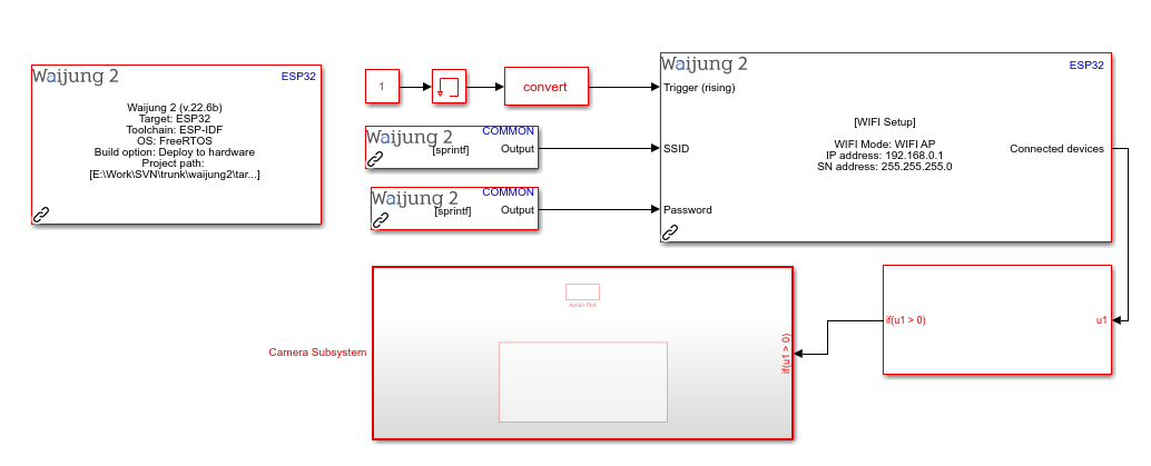
In the AP mode, esp32 will create its own wifi network. There, the user has to input SSID and Password to connect any device to the network. Under the wifi setup block configurations, users can specify the streaming IP address in the text field marked by the blue color box.
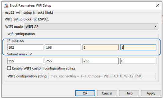
For example, This will transmit the still image to http://192.168.0.1/capture. Video will be streamed by http://192.168.0.1:81/stream web address. Users can view it from any web browser. Make sure all devices are connected to the same network.
STA mode
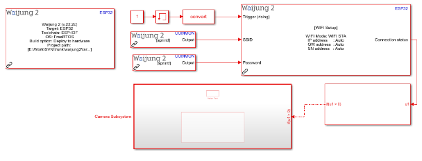
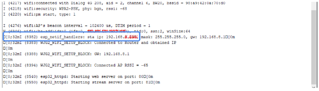
In STA (station) mode, user requires an external network connection to connect to esp32. Under the Wifi setup block, select the correct mode to proceed. In this mode, esp32 will be connected to another host network and the IP of the esp32 can be monitored in the serial monitor when it established the connection. The blue-colored box in the following picture shows where the IP can be found for the user.
Same as the AP mode this can also get the video and still images by the web browser by the link below.
http://(esp32 ip address)/capture
http://(esp32 ip address):81/stream
How to prepare the board to upload the code.
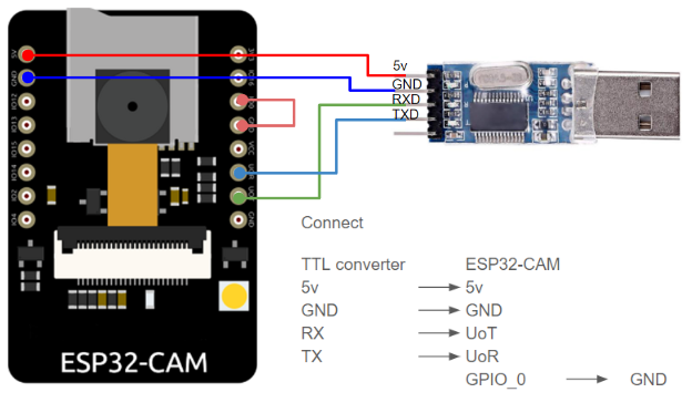
ESP32-CAM board does not have any USB port to upload the code. There we have to use a USB to TTL converter. The picture below shows, how to prepare the board for the code upload. Once the TTL converter is connected to the computer, make sure to press the reset button. Then the board will initiate the download mode.
Upload to the ESP32-CAM board
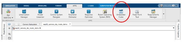
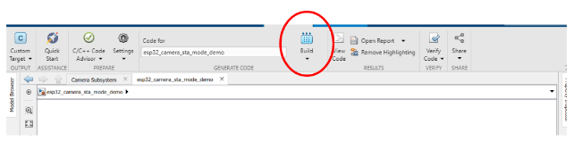
Users can upload the code. If users cannot see the C CODE tab, follow the picture to enable it.
Click Embedded Coder in the APPS tab.
Navigate to the C CODE tab and click the build button to upload the code. This will take some time to generate the code and flash it to the board.
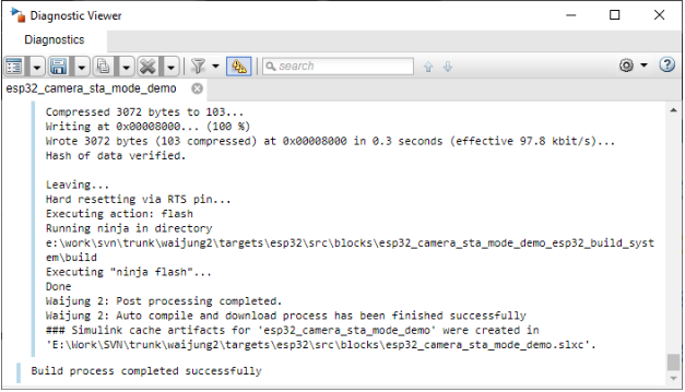
Once everything is finished you will be able to see this message.
Display Real-time Image in Simulink
Displaying the image in the Simulink can be obtained by a simple program like this. This required Simulink Computer Vision Toolbox.
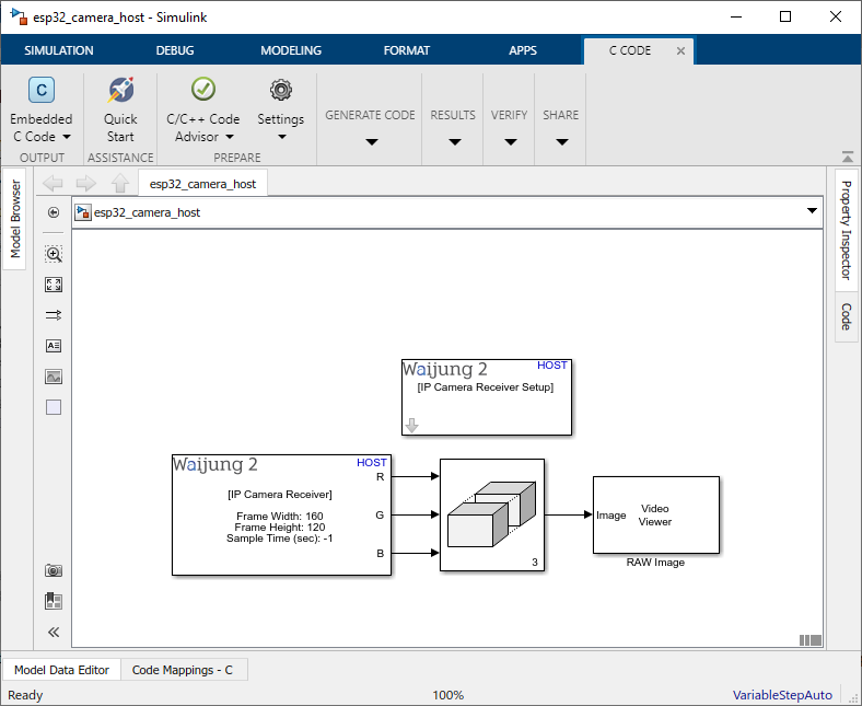
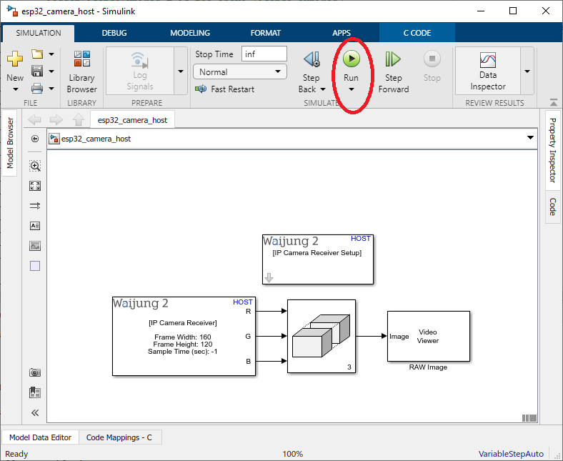
Here it uses four blocks, the IP Camera Receiver Setup block, IP Camera Receiver block, Video Viewer block and Matrix Concatenate block. In the setup block, it will set required environment paths for Matlab. Then IP Camera Receiver block will grab the image and send the output by separating it into 3 colors (Red, green and Blue) via 3 ports. In the mask, users have to mention the following details.
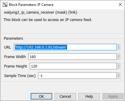
URL : IP to receive the image from the camera. For example: http://(esp32 ip address):81/stream
Frame width: Width of the camera image. Use the same width when configuring the camera config in the previous examples
Frame height: Hight of the camera image. Use camera config image height.
Matrix Concatenate block combines all 3 color channels together. Then Video viewer will display the image output from the camera
Note: Video viewer can be found in the Computer Vision Toolbox.
An example mask for the IP Camera Receiver block can be seen in the following picture.
Click the run button to execute the program (User doesn't want to upload the program to the board).
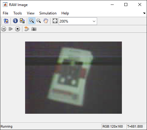
It will open the video for the given IP camera. If it didn’t open, double click on top of the video viewer block. It will open the output of the camera video.
Please find the example files from here: