Introduction
The Waijung 2, ESP32 embedded target allows the user for Code Verification and Validation in ESP32 using Processor-In-the-Loop(PIL) Simulation. Using this simulation mode, user can test whether the model and generated code are numerically equivalent. Simulink PIL supports three different simulation modes. For more information go to Code Verification and Validation with PIL.
Configuration parameters
There are several configuration parameters that are related to the PIL simulation Mode functionality. Traditionally, these parameters are modified using the Model Configuration Dialog Box. However, for convenience Waijung 2 has included all the available configurations in Waijung2 Target Setup Block.
Configuration Parameter |
Selectable Option/Value |
Description |
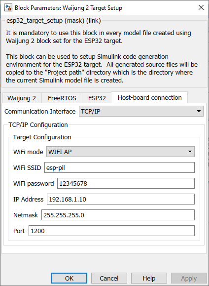
Communication Interface |
TCP/IP--Serial |
Select communication interface to initiate the external mode connection |
WiFi mode |
WFI AP--WIFI STA |
Select the WiFi mode for communication. |
WiFi SSID |
|
Depending on the WiFi mode selected, enter the SSID of the network. |
WiFi password |
|
Depending on the WiFi mode selected, enter the password of the network. |
IP Address |
|
Enter the IP address. |
Netmask |
|
Enter the netmask. |
Enable manual DNS IP |
check--uncheck |
Check to add a custom DNS IP. This will only appear in WIFI STA mode. |
DNS IP |
|
Insert the custom DNS IP. This will only appear in WIFI STA mode |
Port |
|
Enter the port to be used. |
UART Module |
0--1 / 0--1--2 |
Select UART port number for the external communication |
Baud rate (bps) |
|
Enter baud rate for the external communication |
Tx pin |
0 to (Num of max GPIO pins for the ESP32 traget family) |
Tx pin for external communication |
Rx pin |
0 to (Num of max GPIO pins for the ESP32 traget family) |
Rx pin for external communication |
Serial Port |
|
Com port to connect External mode serial connection |
Timeout |
|
Specify the timeout period when Simulink tries to connect to the target in seconds. |
Setting up Simulink model for PIL simulation mode
Two Simulink models are required for the PIL simulation using Model block Simulation mode; For more information go to Verify generated code using PIL Simulation for Model Blocks.
Reference model and Top model.
•Reference model
This model is used to contain all the blocks which are related to the task (algorithm) that should be run on the target. Add the required input and outputs using input ports and output ports.
•Top model
Top model can be used to send the input signals to the reference model and monitor the output signals from the reference model. In addition to that, this model is used to simulate algorithms on the host and can be compared with the reference model outputs(Note: driver specific blocks cannot be simulated on the host).
Note: Model block is used on the Top model to link the Reference model with the Top model.
The following steps are required to set up any Simulink model for PIL simulation.
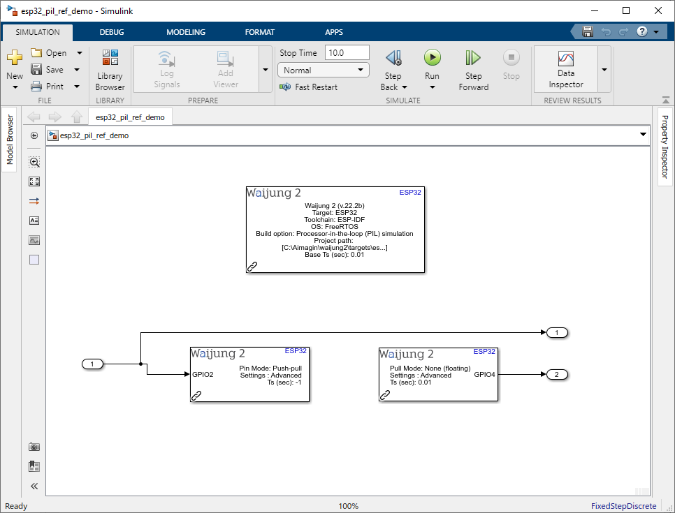
In the Reference model,
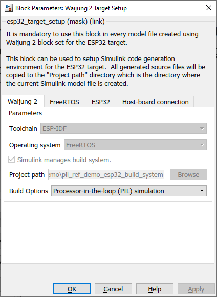
1.Set the Build options to Processor-in-the-loop simulation in the Waijung2 tab and click Apply. Host-board connection tab would appear on the block mask.
2.From the Host-board connection tab, setup necessary WiFi configurations.
3.Implement the algorithm for the target and add required input and output ports and save the model.
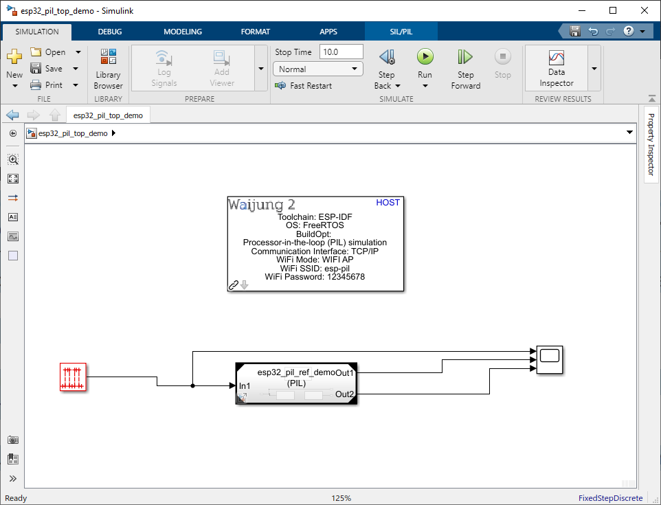
In the Top model,
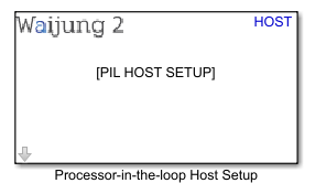
1.Add the Processor-in-the-loop host setup block,
This block is only used to set required Model Configuration parameters in the Top model.
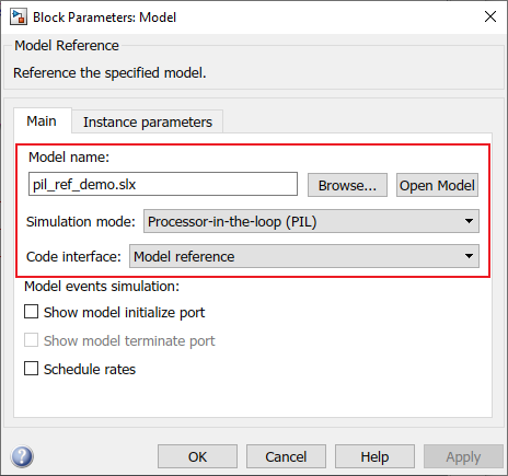
2.Add a Model block to link the Reference model. In the Model block mask,
a.Browse the reference model file
b.Change the Simulation mode to Processor-in-the-loop
c.Change the Code interface to Model reference
3.Connect the input and output port of the model block to required inputs (e.g: pulse generators, constant blocks,... ) and outputs (e.g: scope,....)
4.To enable the SIL/PIL toolstrip on Simulink go to Apps → SIL/PIL Manage
5.Then go to SIL/PIL tab,
a.Change the Mode to Automated Verification
b.Change the System Under Test to Model blocks in SIL/PIL mode
c.Change the Top Model Mode to Normal
d.Set the Stop Time to finite value
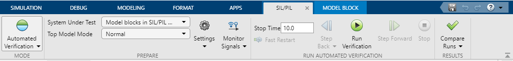
6.Save the model file and click on the Run Verification button on the SIL/PIL tab to build, compile and run the simulation
7.Once the simulation is finished, open the scope or output source to see the simulation data
8.If you need to see the code execution profiling report, in the Top model go to SIL/PIL tab → Compare Runs → Generate Report. It will generate a report about the execution profiling
Demo
Demo 1: PIL demo tcp/ip
Reference model
Demo file: esp32_pil_ref_demo.slx
Top model
Demo file: esp32_pil_top_demo.slx
Description
This is a simple example to showcase the capabilities of using the PIL feature. In this model, GPIO Out block is used to generate the signal from GPIO2 pin which is input from the Top model (pil_demo_top.slx) and the GPIO Input block is used to read the GPIO4 and output that signal to the Top model. And in addition to that, the input signal is directly sent to the Top model. The demo file is configured to use WiFi AP mode as the communication interface for PIL simulation.
Note: Before running the simulation, short circuit the GPIO2 and GPIO4 pins.
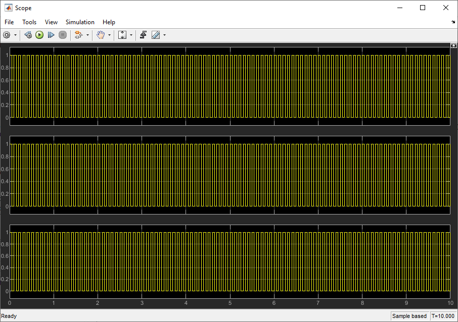
When the simulation starts running, double-click to open the Scope. This simulation runs for 10 seconds.
Setup
1.Go to SIL/PIL tab and select Run Verification to Build, Compile, Upload the executables and start the PIL simulation
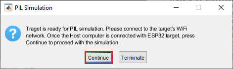
2.Once the Uploading process is finished, a message box will be popped up to continue the simulation
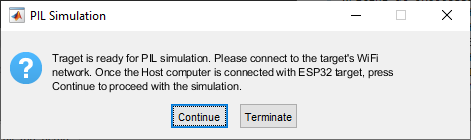
3.Before selecting on Continue, connect the host computer to the target's WiFi network to start the simulation with following data
a.SSID: esp-pil
b.Password: 12345678
4.Select Continue to proceed with the PIL simulation
What should be happening?
The scope plots the simulated input signals and the digital input output readings from the target hardware.
The code execution profiling report can be generated by going to SIL/PIL tab → Compare Runs → Generate Report in the Top model.
Demo 2: PIL demo serial
Reference model
Demo file: esp32_pil_serial_ref_demo.slx
Top model
Demo file: esp32_pil_serial_top_demo.slx
Description
The demo file is configured to use Serial as the communication interface for PIL simulation. This example is the same example from the TCP/IP but PIL working from Serial. Check the previous demo description for details.
Note: Before running the simulation, short circuit the GPIO2 and GPIO4 pins.
When the simulation starts running, double-click to open the Scope. This simulation runs for 10 seconds.
Setup
1.Go to SIL/PIL tab and select Run Verification to Build, Compile, Upload the executables and start the PIL simulation
There will be no message shoes after the program uploaded to the Target board. Simulation will start soon after upload is done. Make sure to open Scope to check results.
What should be happening?
The scope plots the simulated input signals and the digital input output readings from the target hardware.