Introduction
The Waijung 2 ESP32 embedded target allows the user to monitor applications running in the microcontroller using External Mode. It gives the possibility for the user to modify the parameters of the application running on ESP32 and visualize results from Simulink.
Configuration Parameters
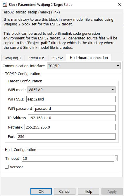
There are several configuration parameters that are related to the External Mode functionality. Traditionally, these parameters are modified using the Model Configuration Dialog Box. However, for convenience Waijung 2 has included all the available configurations in Waijung2 Target Setup Block.
Configuration Parameter |
Selectable Option/Value |
Description |
Communication Interface |
TCP/IP--Serial |
Select communication interface to initiate the external mode connection |
WiFi mode |
WFI AP--WIFI STA |
Select the WiFi mode for communication. |
WiFi SSID |
|
Depending on the WiFi mode selected, enter the SSID of the network. |
WiFi password |
|
Depending on the WiFi mode selected, enter the password of the network. |
IP Address |
|
Enter the IP address. |
Netmask |
|
Enter the netmask. |
Port |
|
Enter the port to be used. |
UART Module |
0--1 / 0--1--2 |
Select UART port number for the external communication |
Baud rate (bps) |
|
Enter baud rate for the external communication |
Tx pin |
0 to (Num of max GPIO pins for the ESP32 traget family) |
Tx pin for external communication |
Rx pin |
0 to (Num of max GPIO pins for the ESP32 traget family) |
Rx pin for external communication |
Serial Port |
|
Com port to connect External mode serial connection |
Timeout |
|
Specify the timeout period when Simulink tries to connect to the target in seconds. |
Verbose |
Check--Uncheck |
To view the external mode execution progress and updates in the Diagnostic Viewer or in the MATLAB® command window, select this check box |
Setting Up Simulink Model for External Mode
The following steps are required to set up any Simulink model for external mode simulation.
1.Open Waijung2 Target Setup Block mask and Set the Build options to External mode simulation in the Waijung2 tab and click Apply. Host-board connection tab would appear on the block mask.
2.From the Host-board connection tab, select the preferred communication interface, and fill in the necessary configurations for the selected interface.
3.In the Hardware tab in the Simulink model window, change the Stop Time to inf.
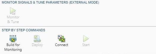
4.Go to Monitor & Tune dropdown under Run on Hardware group in Hardware tab and select Build for Monitoring to build, compile and upload the model to the target
5.Once the build process is finished, if WIFI AP mode is selected, connect your computer to the access point created by the esp32 using the specified SSID and password. If WIFI STA mode is selected, make sure the computer is also connected to the same network specified in the SSID parameter.
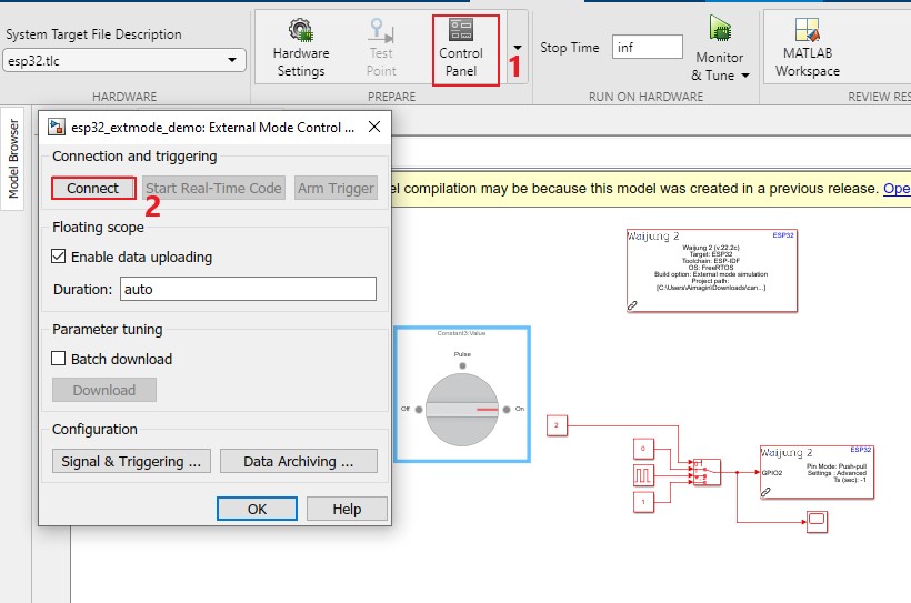
6.Select Connect button to start the simulation. If the Connect button is disabled under Monitor & Tune, use the Control Panel in Hardware tab to connect to the target ESP32.
7.If Verbose is ‘on’, open the Diagnostic Viewer.
Demo
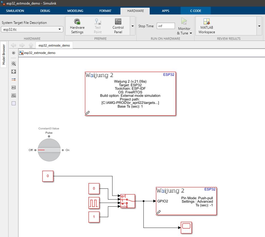
ext_mode demo tcp/ip
Demo file : esp32_extmode_demo.slx
Description
This example shows how to use the External Mode feature with the Waijung 2 block set. In the example, GPIO 2 is connected to an LED. A Simulink Index Vector is used to control the input of the GPIO pin. The control port of the Index Vector block is controlled using a Simulink Rotary Switch.
Setup
1.Go to Monitor & Tune dropdown under Run on Hardware group in Hardware tab and select Build for Monitoring to build, compile and upload the model to the target
2.Once the build process is finished, if WIFI AP mode is selected, connect your computer to the access point created by the esp32.
oSSID - esp32ssid
oPassword - password
3.Select Connect to start the simulation.
What should be happening?
After connecting with the target, depending on the selection of the Rotary Switch, a different output will be visible at the GPIO 2. If Rotary Switch is set to,
•Off: The LED will be off
•Pulse: The LED will toggle at a frequency of 1 Hz.
•On: The LED will be on.
Demo
ext_mode demo serial
Demo file : esp32_extmode_serial_demo.slx
Description
This example shows how to use the External Mode feature with the Waijung 2 block set. In the example, GPIO 2 is connected to an LED. A Simulink Index Vector is used to control the input of the GPIO pin. The control port of the Index Vector block is controlled using a Simulink Rotary Switch.
Setup
1.Do the basic configurations in the esp32_target_setup block & select Build Options as External mode simulation.
2.Go to Host-board configuration tab and select Serial as the Communication Interface in esp32_target_setup block. For each ESP32 family have different number of UART modules. Check the datasheet of the board to find the tx and rx pins related to the UART module. Usually UART0 is connected to programming Serial port. For instance, this example is based on ESP32-WROOM board:
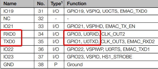
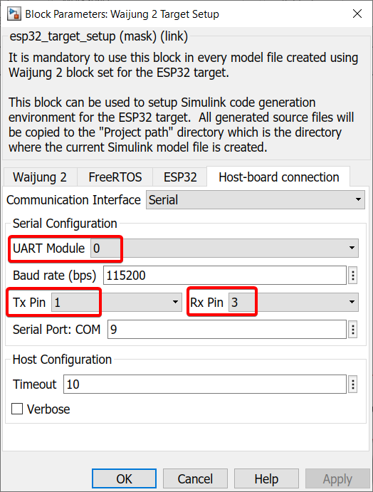
The above image is from the ESP32-WROOM datasheet where UART0 module's transmitter (Tx) and receiver (Rx) are represented by GPIO 1 and GPIO 3, respectively. These are the configurations needed for the Waijung 2 target setup block as shown in the image below. Make sure you check your board's datasheet to find the correct Tx and Rx pins related to the UART module.
3.Go to Monitor & Tune dropdown under Run on Hardware group in Hardware tab and select Build for Monitoring to build, compile and upload the model to the target
4.Select Connect to start the simulation.
What should be happening?
After connecting with the target, depending on the selection of the Rotary Switch, a different output will be visible at the GPIO 2. If Rotary Switch is set to,
•Off: The LED will be off
•Pulse: The LED will toggle at a frequency of 1 Hz.
•On: The LED will be on.