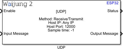
How this block appears in a Simulink model?
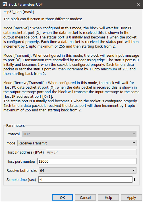
What can be configured?
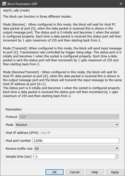
•Receive mode:
Configuration Parameter |
Selectable Option/Value |
Description |
Protocol |
UDP |
UDP protocol will be used to transmit messages. |
Mode |
Receive--Transmit--Receive/Transmit |
Select the mode in which the block should act as. The information on each mode can be found in How does this block work? section. |
Host IP address (IPV4) |
Any IP |
|
Host port number |
|
Enter the port number of the host. |
Receive buffer size |
16--32--64--128--256 |
Select the buffer size of the receiver. This indicates the number of characters to be received. |
Sample time (sec) |
-1 (inherited) or specify |
Specify the sample time. |
Port Name |
Port Type |
Date Type |
Description |
Enable |
Scalar |
uint8 |
If 1 is received, the block will initialize the port. If 0 is received, the block will deinitialize the port and it can be used by another block. |
Status |
Scalar |
uint8 |
The status port is 0 initially and becomes 1 when the socket is configured properly. Each time a data packet is received the status port will then increment by 1 up to a maximum of 255 and then start back from 2. |
Output Message |
Vector |
uint8 |
Output the message received as a character vector. |
Remark: It is not recommend to use the Enable input port to open and close the UDP sockets time to time in the receive mode since it losses the connection as well as the incoming data.
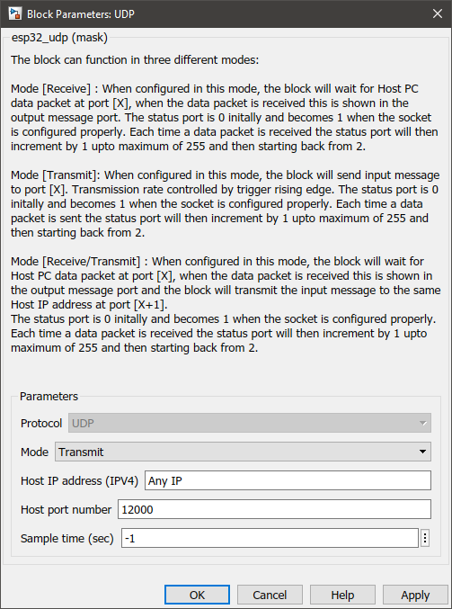
•Transmit mode:
Configuration Parameter |
Selectable Option/Value |
Description |
Protocol |
UDP |
UDP protocol will be used to transmit messages. |
Mode |
Receive--Transmit--Receive/Transmit |
Select the mode in which the block should act as. The information on each mode can be found in How does this block work? section. |
Host IP address (IPV4) |
|
Specify the IP address. |
Host port number |
|
Enter the port number of the host. |
Sample time (sec) |
-1 (inherited) or specify |
Specify the sample time. |
Port Name |
Port Type |
Date Type |
Description |
Enable |
Scalar |
uint8 |
If 1 is received, the block will initialize the port. If 0 is received, the block will deinitialize the port and it can be used by another block. |
Input Message |
Vector |
uint8 |
The message to be transmitted can be input from this port as a character vector. |
Trigger |
Scalar |
uint8 |
This port can be used to adjust the transition frequency of the block. The block only transmits when this port receives 1. |
Status |
Scalar |
uint8 |
The status port is 0 initially and becomes 1 when the socket is configured properly. Each time a data packet is received the status port will then increment by 1 up to a maximum of 255 and then start back from 2. |
•Receive/Transmit mode:
Configuration Parameter |
Selectable Option/Value |
Description |
Protocol |
UDP |
UDP protocol will be used to transmit messages. |
Mode |
Receive--Transmit--Receive/Transmit |
Select the mode in which the block should act as. The information on each mode can be found in How does this block work? section. |
Host IP address (IPV4) |
Any IP |
|
Host port number |
|
Enter the port number of the host. |
Receive buffer size |
16--32--64--128--256 |
Select the buffer size of the receiver. This indicates the number of characters to be received. |
Sample time (sec) |
-1 (inherited) or specify |
Specify the sample time. |
Port Name |
Port Type |
Date Type |
Description |
Enable |
Scalar |
uint8 |
If 1 is received, the block will initialize the port. If 0 is received, the block will deinitialize the port and it can be used by another block. |
Input Message |
Vector |
uint8 |
The message to be transmitted can be input from this port as a character vector. |
Status |
Scalar |
uint8 |
The status port is 0 initially and becomes 1 when the socket is configured properly. Each time a data packet is received the status port will then increment by 1 up to a maximum of 255 and then start back from 2. |
Output Message |
Vector |
uint8 |
Output the message received as a character vector. |
When to use this block?
This block is used to send/receive messages via the UDP protocol.
How does this block work?
This block can operate in three different modes:
•Mode [Receive]: When configured in this mode, the block will wait for the Host PC data packet at port [X], when the data packet is received this is shown in the output message port. The status port is 0 initially and becomes 1 when the socket is configured properly. Each time a data packet is received the status port will then increment by 1 up to a maximum of 255 and then start back from 2.
•Mode [Transmit]: When configured in this mode, the block will send input messages to port [X]. Transmission rate controlled by trigger rising edge. The status port is 0 initially and becomes 1 when the socket is configured properly. Each time a data packet is sent the status port will then increment by 1 up to a maximum of 255 and then start back from 2.
•Mode [Receive/Transmit]: When configured in this mode, the block will wait for the Host PC data packet at port [X], when the data packet is received this is shown in the output message port, and the block will transmit the input message to the same Host IP address at port [X+1].
The status port is 0 initially and becomes 1 when the socket is configured properly. Each time a data packet is received the status port will then increment by 1 up to a maximum of 255 and then start back from 2.
Demo
Demo file : esp32_udp_demo.slx
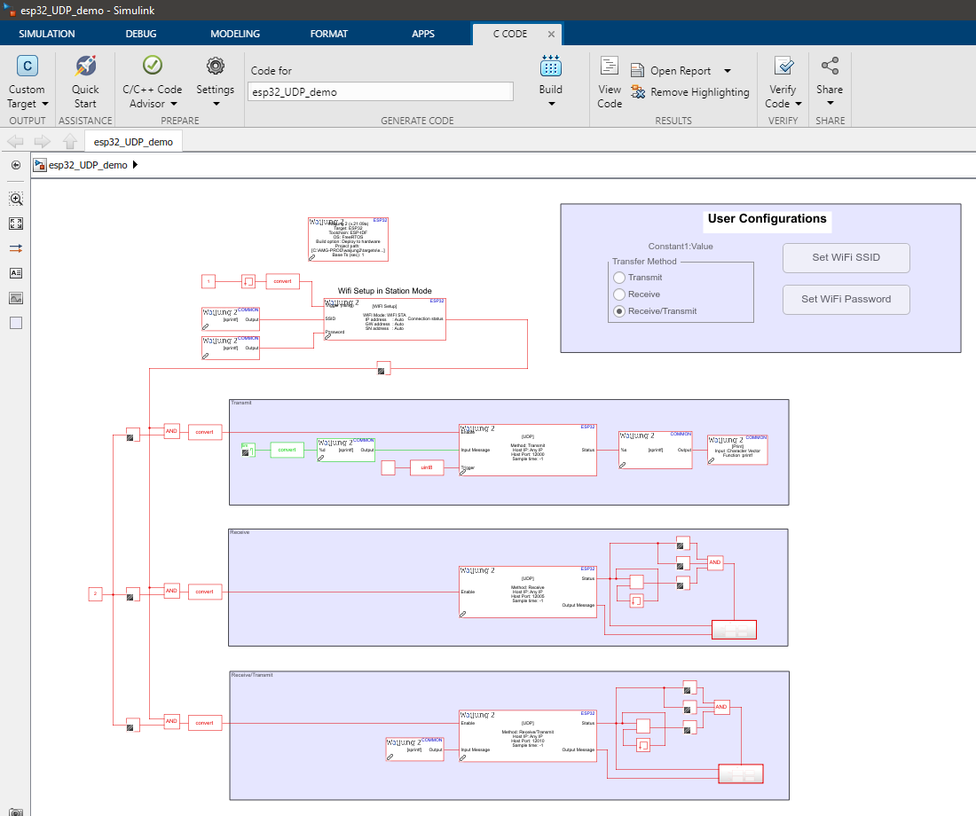
Description
This example shows how to use the UDP_block to transfer messages via the UDP protocol. This demo showcases all three modes of execution of this block namely, Receive, Transmit and Receive/Transmit. For the simplicity of the demonstration, this model can only be configured to work in a single mode at any given time. However, it is worth noting that there can be multiple instances of the block with different modes on the same model working in parallel, as long as the port names do not conflict.
Setup
The following software is needed to get the expected results:
1.A serial monitor software application. For this example, PuTTY open-source SSH and telnet client is used to monitor the serial output.
2.A utility software that allows sending and receiving UDP packets. For this example, Packet Sender is used.
Before running the demo model there are several configurations to be modified. These parameters are the WiFi SSID, WiFi password, and execution mode. They can be configured at the User Configurations area of the model file.
What should be happening?
Let's consider each mode of execution separately.
•Receive
Follow the steps below:
1.Select the Receive in the Transfer Method radio button at the User Configurations area.
2.Set WiFi username and password using the respective buttons at the User Configuration area. Make sure the SSID specified here is the same SSID that the computer to which you are going to run the Packet Sender software is connected.
3.Build and upload the model.
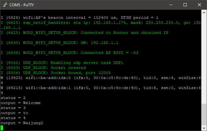
4.Open the PuTTY software and connect to the serial port with a baud rate of 115200. Identify the IP address of the microcontroller and the port.
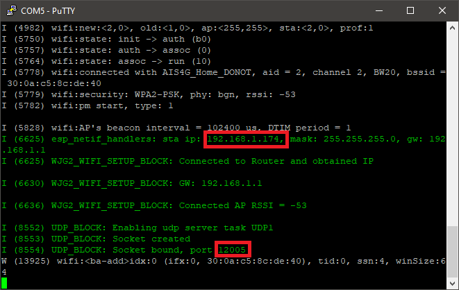
5.Open the Packet Sender software and enter the Address. Set Port to 12005, and Protocol to UDP.
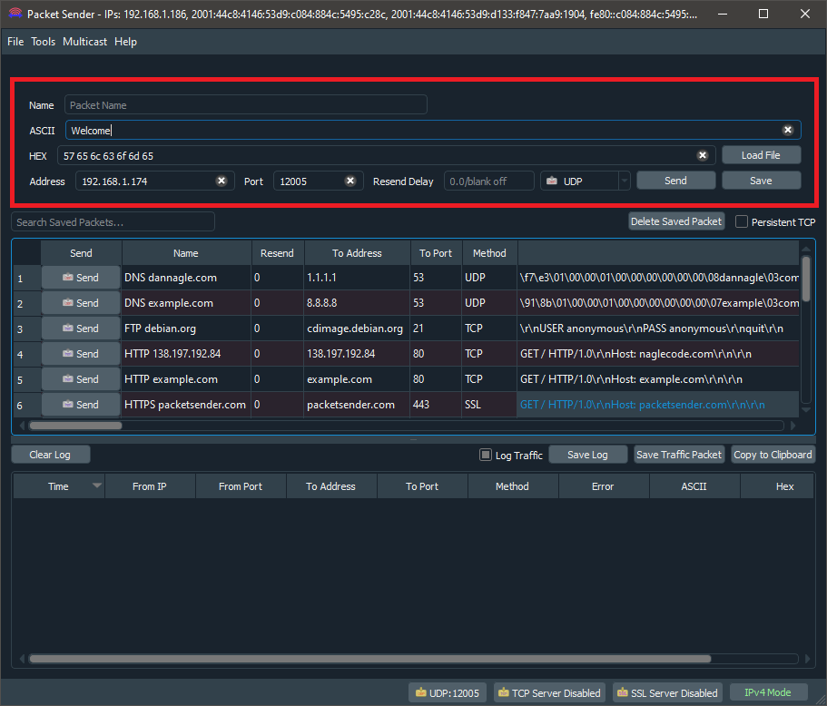
6.In the Packet Sender software type "Welcome" in the ASCII text field and press the Send button. Repeat the process with the messages "to", "Waijung2". On the serial monitor, the end result would look something similar to what is shown below.
•Transmit
Follow the steps below:
1.Select the Transmit in the Transfer Method radio button at the User Configurations area.
2.Set WiFi username and password using the respective buttons at the User Configuration area. Make sure the SSID specified here is the same SSID that the computer to which you are going to run the Packet Sender software is connected.
3.Build and upload the model.
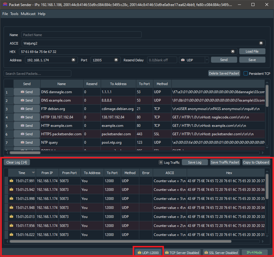
4.Open the Packet Sender software and set the Port at File->Settings->Network->UDP Server Ports (comma-separated, 0 for random) to 12000. Enable the UDP Server and disable the TCP Server and SSL Server at the bottom of the window.
5.On the serial monitor, the end result would look something similar to what is shown below. The Counter value increment from 0-7 in one-second steps and repeat.
•Receive/Transmit
Follow the steps below:
1.Select the Receive in the Transfer Method radio button at the User Configurations area.
2.Set WiFi username and password using the respective buttons at the User Configuration area. Make sure the SSID specified here is the same SSID that the computer to which you are going to run the Packet Sender software is connected.
3.Build and upload the model.
4.Open the PuTTY software and connect to the serial port with a baud rate of 115200. Identify the IP address of the microcontroller and the port.
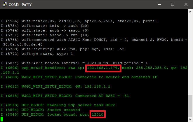
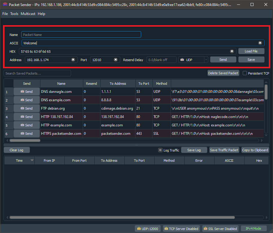
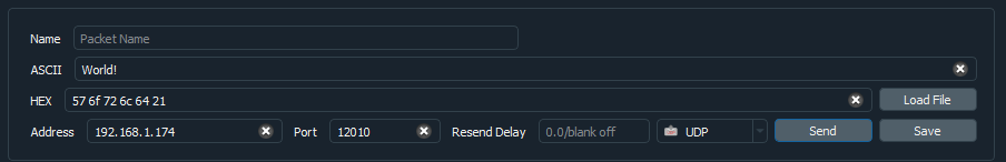
5.Open the Packet Sender software and enter the Address. Set Port to 12010, and Protocol to UDP. From here onwards this window will be known as "Instance 1" of Packet Sender software.
6.Open another window of Packet Sender software (a separate instance) set the Port at File->Settings->Network->UDP Server Ports (comma-separated, 0 for random) to 12011 and enable the UDP Server and disable the TCP Server and SSL Server at the bottom of the window. From here onwards this window will be known as "Instance 2" of Packet Sender software
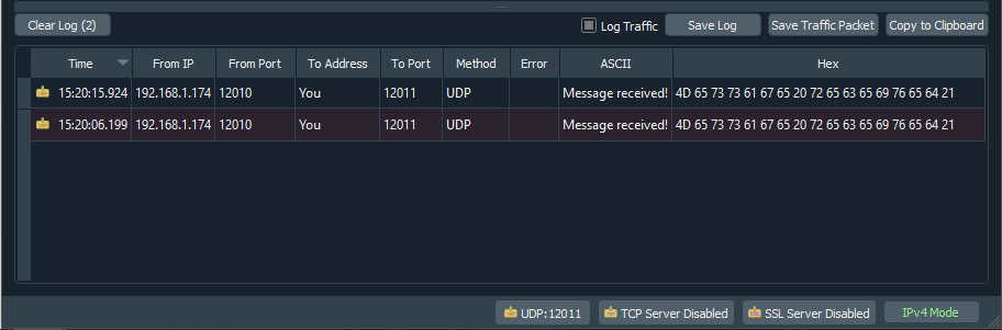
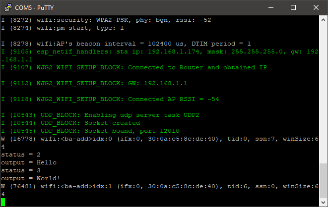
7.In Instance 1 of the Packet Sender software type "Hello" in the ASCII text field and press the Send button. Repeat the process with the message "World!". The Instance 1 of the software is used to send messages to the microcontroller and the serial monitor can be used to check the message sent. In this mode When a message is received from port x (12010 in this example), another message is sent back (in this example it is the "Message received!" text) to the host from port x+1 (12011 in this example.). The result should look something similar to what is shown below.
oInstance 1 of the Packet Sender software
oSerial monitor
oInstance 2 of the Packet Sender software