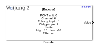
How this block appears in a Simulink model?
What can be configured?
Configuration Parameters |
Selectable Option/value |
Description |
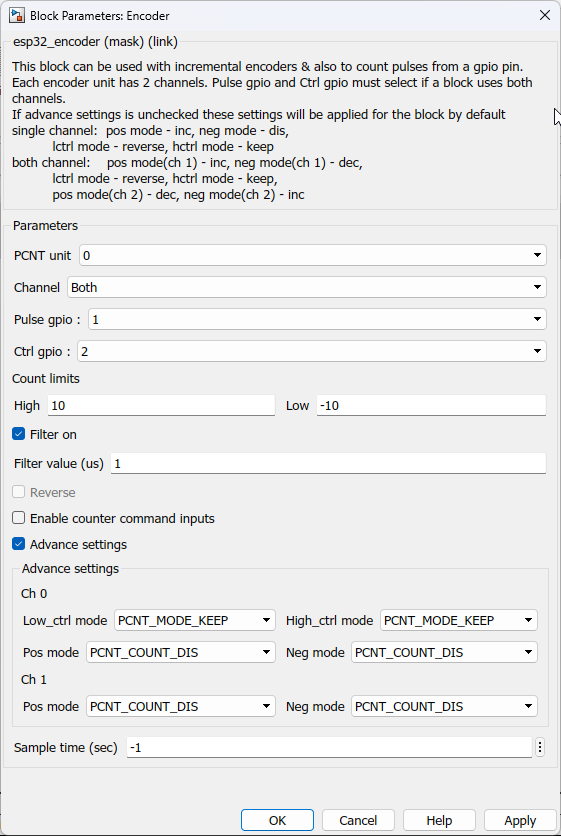
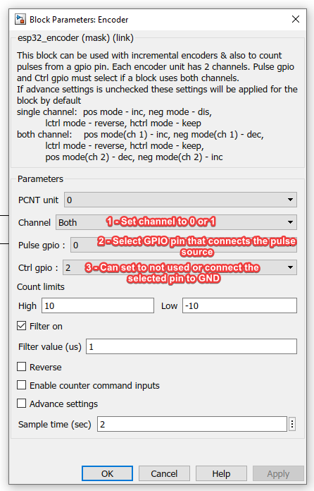
PCNT Unit |
0--1--2--3 |
PCNT module contains 4 units which can be used simultaneously, Same number cannot be configured for multiple blocks in one Simulink application |
Channel |
0--1--Both |
Selection of channels available for a single PCNT unit. |
Pulse gpio |
Not used--All gpio pins supported to target family |
Select Pulse gpio pin. |
Ctrl gpio |
Not used--All gpio pins supported to target family |
Select Ctrl gpio pin. |
Count limits high |
|
Maximum counter value. By default, Interrupt handler is there to handle this. |
Count limits low |
|
Minimum counter value. By default, Interrupt handler is there to handle this. |
Filter on |
Check--Uncheck |
Enable filter for the input signal. |
Filter value |
|
Set PCNT filter value. The maximum filter value should be limited to 1023. |
Reverse |
Check--Uncheck |
Reverse count value. This will be hidden if the user selects the advance mode. |
Enable counter command inputs |
Check--Uncheck |
Enable an input port to start, pause & clear the counter values. 0 = start, 1 = pause, 2 = clear |
Advance settings |
Check--Uncheck |
Open advance settings for configuration. |
Low_ctrl_mode |
PCNT_MODE_KEEP--PCNT_MODE_REVERSE--PCNT_MODE_DISABLE |
PCNT low control mode |
High_ctrl_mode |
PCNT_MODE_KEEP--PCNT_MODE_REVERSE--PCNT_MODE_DISABLE |
PCNT high control mode |
Pos mode(Ch 0) |
PCNT_COUNT_DIS--PCNT_COUNT_INC--PCNT_COUNT_DEC |
PCNT high control mode for main channel |
Neg mode(Ch 0) |
PCNT_COUNT_DIS--PCNT_COUNT_INC--PCNT_COUNT_DEC |
PCNT negative edge count mode for the main channel |
Pos mode(Ch 1) |
PCNT_COUNT_DIS--PCNT_COUNT_INC--PCNT_COUNT_DEC |
PCNT high control mode for the secondary channel(only available if channel selected as both) |
Neg mode(Ch 1) |
PCNT_COUNT_DIS--PCNT_COUNT_INC--PCNT_COUNT_DEC |
PCNT negative edge count mode for the secondary channel(only available if channel selected as both) |
Sample time (sec) |
-1 (inherited) or specify |
Specify the sample time. |
Note:
•This block only works for incremental encoders. This can also be used to count pulses from a single channel.
•ESP32C3 target is not supported for this block.
•If the channel is selected as both, The user must select both pulse and control gpio pins to get the count
•Filtering Pulses: The PCNT unit features filters on each of the pulse and control inputs, adding the option to ignore short glitches in the signals. The maximum filter value should be limited to 1023.
•For the counter not to miss any pulses, the pulse duration should be longer than one APB_CLK cycle (12.5 ns).
If advance settings is unchecked these settings will be applied for the block by default
single channel: pos mode - inc, neg mode - dis, lctrl mode - reverse, hctrl mode - keep
both channel: pos mode(ch 1) - inc, neg mode(ch 1) - dec, lctrl mode - reverse, hctrl mode - keep, pos mode(ch 2) - dec, neg mode(ch 2) - inc
Reverse will change the pos mode and neg mode to reverse the count.
INPUT/ OUTPUT Port
Port Name |
Port Type |
Data Type |
Description |
Value |
Scalar |
int16 |
This output port output the number of counted pulses according to the user define setting in the block mask. |
Counter Commands |
Scalar |
uint8 |
Allows the user to start, pause & clear by the following number input 0 = start, 1 = pause, 2 = clear |
Demo
Demo file : esp32_encoder_demo.slx
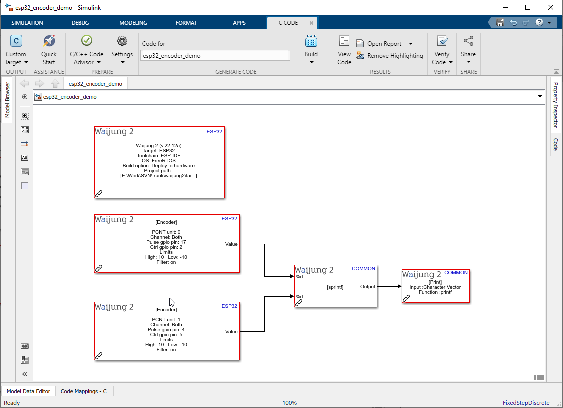
Description
This is a simple example to demonstrate how the encoder block is working. It's using two encoder blocks to get the pulse count from two encoder sensors and output the count value from a print block.
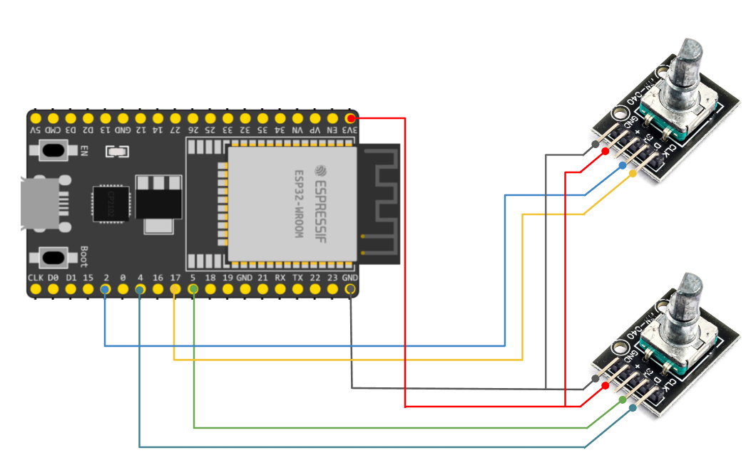
Connect encoder sensors to the correct pin that assign to each block. In this example encoder block one is connected pulse gpio pin to 17 and ctrl gpio pin to 2 & encoder block two is connected pulse gpio pin to 4 and ctrl gpio pin to 5.
This block can be used to read pulse count regardless of the direction. Encoder block parameter should be change as bellow for this scenarios.
Note: If GPIO 0 is selected as a pulse gpio or a ctrl gpio, plug the encoder after the chip is booted up, because chip will automatically switch to the download mode when the esp32 chip is reset while GPIO 0 is low.
What should be happening?
Once the program is written to the target board open the serial monitor to get the output(baud rate - 115200). Turn the encoder to get value as it turns every 2 sec as defined in the example.
Hardware Setup
1. ESP32
2. 2x Encoders